Vertical 4 cycle engine from recycled parts

Home Model Engine Machinist Forum

Help Support Home Model Engine Machinist Forum:

This site may earn a commission from merchant affiliate links, including eBay, Amazon, and others.
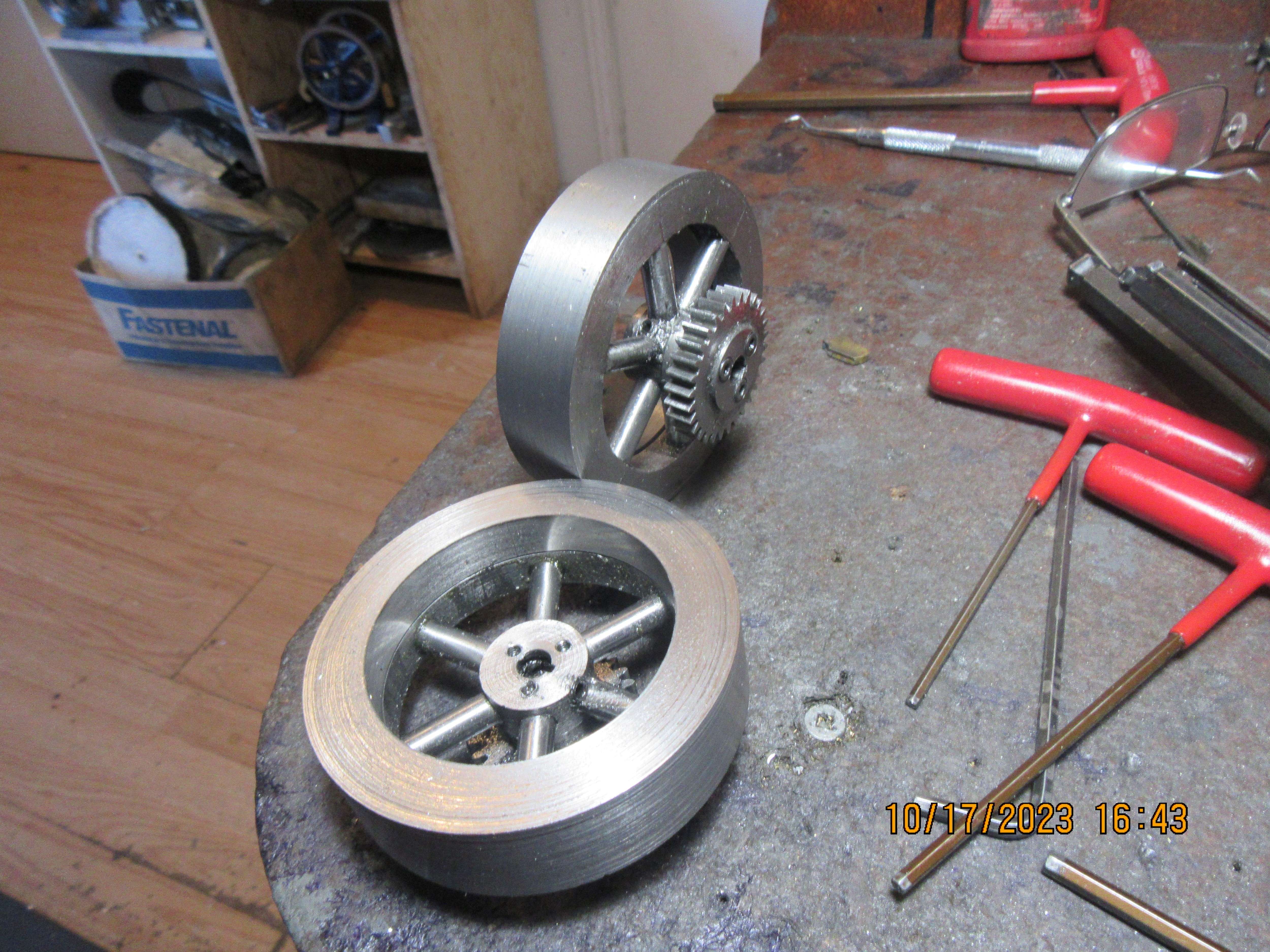
I want to mount the magnet in some manner so that it is not rotationally "fixed" to the cam gear. Since the cam is fixed relative to the large cam gear, I want to be able to set my ignition timing without messing up the cam timing.
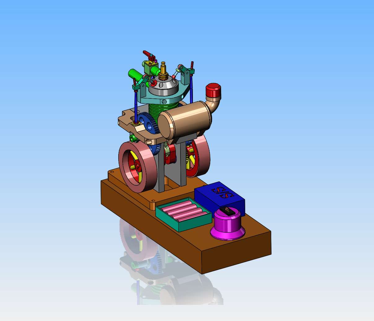
 
Typically the magnet is embedded in (or otherwise fixed to) the moving item and the sensor is mounted on an adjustable bracket on the engine block to adjust the timing.
 
Gordon--I'm sure that may work for you. I arrived at my figures by trial and error, and found that a typical 0.094" wide parting off tool works just fine with the dimensions I have given.---Brian
Brian, your method works if the bore diameter is machined to plan. If the bore is larger or smaller than planned, the groove depth will be affected. I would think that it is better practice to first measure the bore diameter and work backwards from that dimension using the actual o-ring dimensions to determine groove depth based upon whatever ring compression you think is best ( five percent or less ). A few thousandths extra ring compression will result in a very stiff engine such as you just described. As an aside, I do not think ring groove width is all that critical. Rick
 
The groove width IS somewhat important. If the O-ring is not limited in movement it can roll and twist up in the groove. I would think the width should be the same as the cross section of the O-ring to just contain it.
If the groove is too narrow then it can compress the O-ring and make it bulge such that it appears larger in diameter. Not to mention making it tough to insert in the groove.
In my post I stated that the groove width was not critical. By that I meant a few thousandths either way for groove width would not cause problems whereas a few thousandths on groove depth is CRITICAL. Anyone with a modicum of common sense would know that the groove must be wide enough to fit the o-ring without distortion. As for rolling and twisting, if that is a problem, then the groove depth is as the Brits would say: "Not fit for purpose!. You can throw away the o-ring charts when using o-rings for sealing pistons in model engines. Their specifications are designed for high pressure hydraulic situations where overcoming friction is not a problem. In model engines, friction is a MAJOR concern. Rick
 
Today I added a proper gas spout to my gas tank, but the lions share of the day was spent machining "add ons" for my flywheels. They gained 0.1" in diameter and went from 3/8" thick to 3/4" thick. I was going to use brass but I already had a piece of A36 mild steel on hand, so that is what I used.---Brian
rTcnvf.jpg
 
Today, all of the mechanical aspects of the engine are complete. I have to install my new valve springs today, and J.B. Weld my new outer shells to the flywheels. I have to run a flexible gas line from the tank to the carburetor, and I have to set the valve timing. After that, I have to delve into the mysteries of electronic ignition. I think I have every thing that I need now, it's just going to be deciding where to mount everything.---Brian
 
I sent this email off to Roy Sholl--this is a birds eye view of my electronic ignition and a hand made sketch of all the components. When I pass the red end of the magnet past the sensor, I'm not getting a spark at the sparkplug. The batteries are at full charge and the on/off switch is on. I'm sure the problem is at my end. Please comment.---Brian
VxslLu.jpg

XtUJmD.jpg
 
I think that the polarity on the magnet may be wrong. Also the hall sensor will trigger from one side but not the other. Turn the sensor 180. Triggers from the beveled side.
 
The proper end of the magnet can be confusing. The end of the magnet that attracts the north pointer of a compass is the end to use. (the confusing part is that, that is the south pole of the magnet).

Also the active face of the hall sensor is usually the one with the part number on it (at least for all those that I have used) - or as stated - likely the one with the beveled side.
Best to consult the spec sheet for the sensor.

What sensor do you have??

Be aware that you will only get one spark each time you pass the magnet over the sensor.
 
Brian,
The usual magnet is the south pole, some mark the north pole with the red mark. Also the sensor has a narrow band where it will work, any where from 1/16" to just over 1/8". I have a tester to check the pickups and also to set timing, takes all the guess work out of it.
It may be working, you just cant see the spark, as some of the electronic ign systems need to see at least 300rpm before they fire.
Vid shows ign pickup test unit, first is the single pickup, the second is the multi cylinder pickup. Green is South, Red is North

Cheers
Andrew
 
Brian: I am not sure about the s/s system but on some of the modules if you fire it without it being grounded it can burn out the hall sensor.
 
Oxford called it right--One of the batteries was installed backwards. Now when I run the magnet past the sensor, I'm getting a definite "clunk-clunk" from the cdi box, but still no spark at the plug.
 
Put a short ground wire from the spark plug body directly back to the battery pack negative (in addition to the one you already have to the plug body).
 
IF I get the electronic ignition working, the components will be mounted to a wooden sub base. This model is a "quick and nasty" with all the components mounted on top of the wooden sub base. No real provision made here for all the wires, so the battery pack and the CDI may set in a well machined in the wooden sub base with a brass cover plate to hide all the wires.
vP6Tvu.jpg
 
Someone pointed out that I had one of the batteries in the battery pack installed backwards.---DUH---I corrected that, and now when I pass the painted end of the magnet past the sensor, I'm getting a definite "clunk-clunk" sound from the CDI box. ---but still no spark at the plug. There is one wire lead from the junction between the on/off switch and the CDI box (out under the Canadian quarter and the black question mark) that I don't know where it goes to. It is a red wire and a brown wire bonded together.----There are three leads going out from the on/off switch. One, marked "BATT" goes to the batteries. One lead marked "CH" doesn't go anywhere, and I'm assuming it is for a charger. the third lead marked "CDI" goes to the CDI box.---what am I missing?
0eSJ7O.jpg
 
More research shows me that that "mystery lead" may have powered an "on/off" indicator bulb on the engine it was used on 10 years ago.
 
That's correct Brian, it is a lead for an LED to show that the system is on. If you are getting a noise inside the box it is most likely the spark coil. If you carefully pry at the 3 openings you can pop the bottom off the CDI box. You will have to slide a knife down to the 4th pin or it will break off if you just lift the lid. That aching at the spark coil is one of the reasons I went to potting the CDI's. I'm quite sure that yours will not be potted. You could cover that end of the spark coil with silicone sealant. Most often the spark would jump from the spark plug wire back to the input pin on the primary side. A photo of the inside of the CDI box would help.
 
Okay Roy--Here ya go. I was able to pop the top of the CDI box without breaking anything. These three pictures are the inside of the box. What do I do now to fix things?---Brian
NbAS0b.jpg

YhrdUU.jpg

PPVgXf.jpg
 

Latest posts

Back
Top