I dont think the guide spool will be a problem but that is way down the road and there are a lot of bridges to cross before that one.
Bridge One: Cylinders
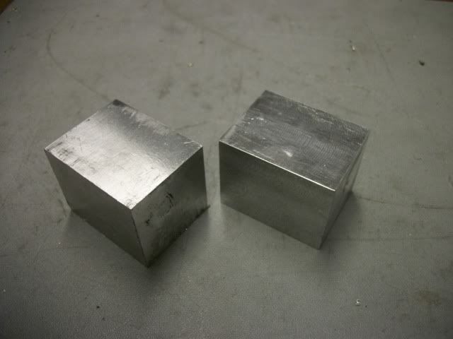
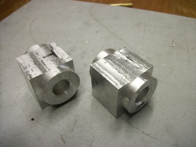
I got s little start today so here it is. Two blocks of aluminum 1 1/4" square by 1 5/8" long worked out of a larger piece using the table saw and brought to dimension on the mill.
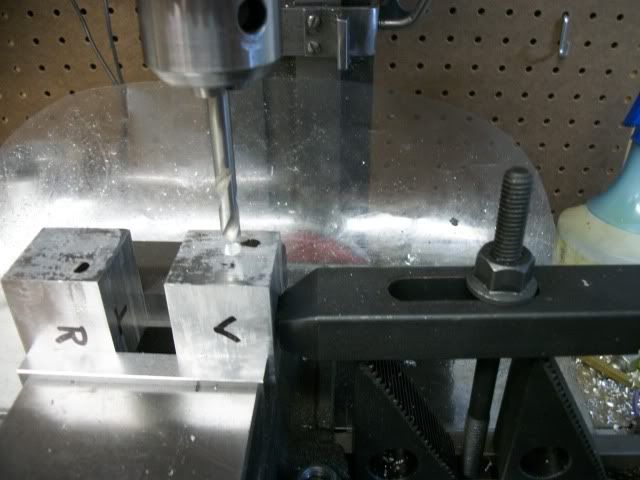
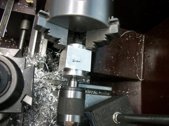
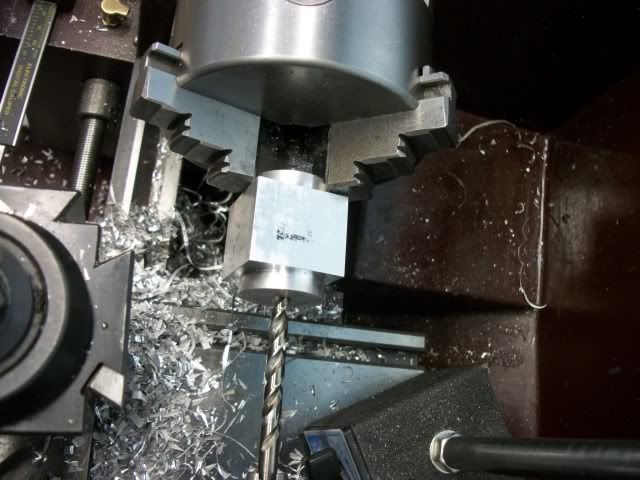
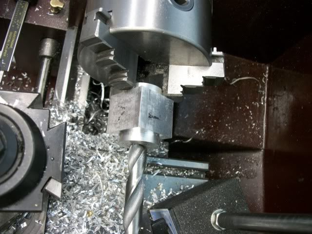
The first task is to locate the center of the bore on opposite faces. This is not the center of the face; it is .500" from each of two adjacent edges. A 15/32" hole is drilled in each face for centering in the lathe
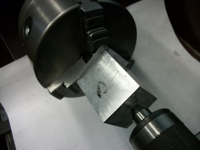
Yes, I know I could use a 4 Jaw chuck to hold the part but I haven't gotten around to ordering one for the lathe and I think my method is just as accurate and much faster. This is much like turning between centers. The headstock center that I will use is a piece of 1/4" rod on which one end has been turned a shallow taper. The rod is held in the 3 jaw and one end of the cylinder is seated on it. The tailstock with ball bearing center is brought up to the other end of the cylinder and used to force the 15/32" hole onto the tapered 1/4" rod and the jaws tightened.
When the cylinder is well seated on the rod, the 3 jaw is loosened slightly and the tailstock ram is used to drive the cylinder into full contact with the ends of the chuck jaws. The combination of the forced fit on the tapered rod and the pressure on the jaw faces may be enough to drive the workpiece but in this instance I add a little insurance by putting a piece of double sided sticky paper to the end of the workpiece before seating it on the rod.
Sticky paper is just a square of printer paper that is sprayed with 3M adhesive and stuck on the workpiece. The other side of the paper is sprayed and when pressed against the jaw ends, provides additional traction. I have seen double sided carpet tape used for the same purpose but the paper is more stable than the cloth tape and is much easier to clean since I control how much adhesive to use.
Here is the piece in the lathe ready to turn the first flange:
Now to turn the flange without that anoying "THUMP-THUMP-THUMP" I take the biggest bite that I can. You can use HSS but I have come to rely on cheap brazed carbide bits that I have honed to a super sharp, thumbnail scraping, edge using a cheap $1 diamond wheel in my mini grinder. The brazed carbide chip limits the depth of cut to about 3/8" which sounds like a huge cut, but my 9x20 lathe has plenty of power to handle this cut and I don't think the smaller mini lathes would have a problem with it either.
Why so deep? After a lot of experimentation, I believe that the magnitude of the "THUMP" is not so much a function of the depth of cut but is much more related to the amount of time that the bit is not in contact with the cut. If you only take a small cut, the bit will be in contact 10% and free of contact 90% of the time. As you get closer to a full round cut, the contact percentage increases until it is 100% and the "THUMP" decreases proportionally until it is gone. Taking the deepest possible cut results in almost no "THUMP" and you get to full round in only two passes. Don't take my word for it, watch the following video.

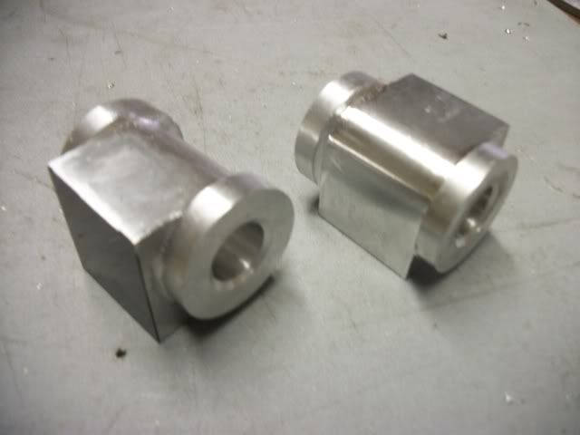
The job here is to turn a 1" diameter flange, 1/4" long on each end. To get the second end just reverse the work piece and repeat. Now, wasn't that easy?
Tomorrow, I'll try to get to profiling the rest of the cylinder and the valve ports.
Jerry