Tiny I.C. Engine

Home Model Engine Machinist Forum

Help Support Home Model Engine Machinist Forum:

This site may earn a commission from merchant affiliate links, including eBay, Amazon, and others.
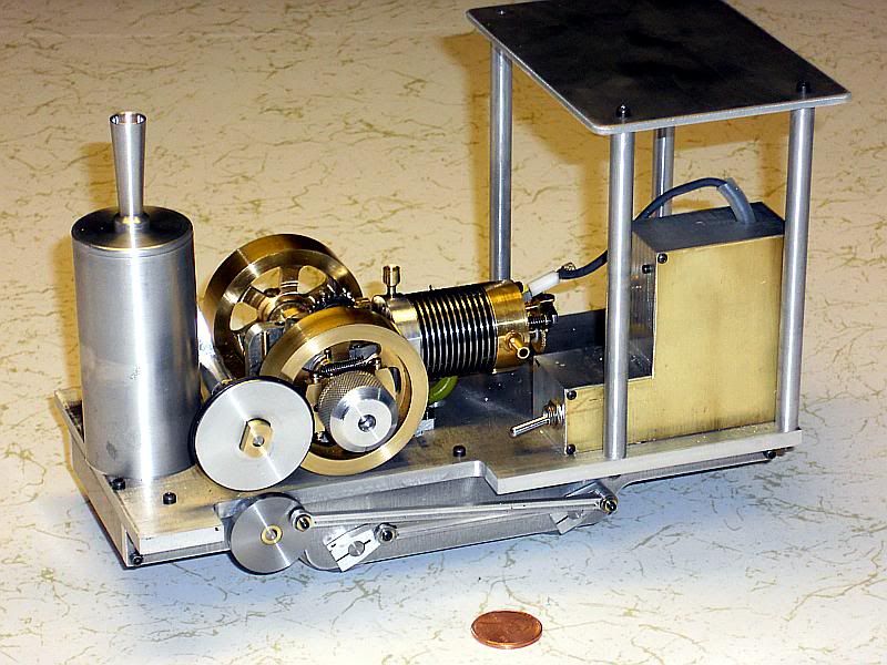
It's been a couple of months since I reported anything on Tiny. I have been mostly working on other projects with Tiny running it the background. When things got slow I would make a few mods to Tiny and run it some more.

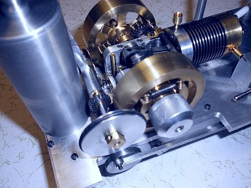
Some of the major changes have been:
Replace the plain crankshaft bearings with ball bearings.
Replace the cam.
Rework the valves.
Take the play out of the hit and miss governor.
Play experimental games with the piston.

Besides reducing the friction on the crankshaft, the ball bearing mod also included taking some of the side play out of the crankshaft. This was necessary as the side play contributed to the hit-miss governor play causing the engine to hit more than once between miss cycles.

The dwell angle on the cam was increased by 10 degrees on the cam, 20 degrees on the crankshaft, to make the engine breathe a little more freely and to make the cam position adjustment easier. The cam was changed from steel to SAE 660 bronze at the same time. That was not really necessary as there was no noticeable wear on either the cam or the follower.

At about 180 hours on the engine the needle valve started to get a little touchy when loading the engine down. It was caused by leakage between the intake valve and valve guide. I knew that I did not get a good finish on the guide when I made it, but had left it alone as I wanted to see the engine run. So the valve guides were re-reamed and new valves made with a little more care this time. Gave a noticeable improvement on the low end rpm recoverable and the needle valve adjustment range was increased.

Removing some of the play in the governor linkage by hand fitting some of the bushings and other areas got rid of the rest of the double hits when it fired.

Lately I have been using Tiny to play with some graphite pistons on an experimental basis. These experiments are documented in a separate thread at:
http://www.homemodelenginemachinist.com/index.php?topic=12591.0
The results have been quite encouraging.

Yesterday I refilled my 500 ml jug of fuel for the third time. So, since starting to use straight gasoline for fuel I have put one liter of fuel through tiny. Most of the time I have been getting 16 to 18 minutes of run time per ml of fuel. Based on that Tiny has 250 to 300 hours of run time on it. Currently with all the changes including the graphite piston I am getting about 21 minutes per ml of fuel.

Gail in NM

 
I will make a few long term running updated on "Tiny" over the next few days.

First is the spark plug.
Some time after 300 plus hours of running time I inspected and replaced the spark plug. The center electrode had eroded flush with the insulator. The electrode is 1/32 music wire. Also the ground electrode showed signs wear. Although I replaced it, it was still working fine.

I don't consider this amount of wear too bad. It's the rough equivalent of 12 to 15 thousand miles of driving and it seems to me that is about when I changed plugs on my 1940's Chevys.

Photos are the plug when new and at replacement.
Gail in NM

Spark-0010.jpg


SparkWear-0001.jpg
 
Hi Gail,
Thanks for the update. I haven't run my Tiny since it was finished, just too many other projects going on. When you went to the lapped piston do you consider this to be one of the better performance improvements that you made? Mine runs good but it and seems to have good compression but it will only hand start on the rarest of occasions.
George
 
very interesting results on the spark plug! Just out of interest, what insulator did you use? It seems to have withstood the heat well. Are you going to replace the electrode with piano wire again or try something else?

I imagine not many models get run for 300 hours so thats a very good test and a credit to the builder :D

Rob,
 
First off thanks for the continued interest. Then, Last things first.

Rob:
The insulator is Corian. It is easy to obtain, very easy to machine and stands up well. Details of the spark plug construction are at:
http://www.homemodelenginemachinist.com/index.php?topic=8096.msg122619#msg122619
There is a PDF file attached to that post with construction details in the following posts.
I am going to continue to use piano wire for the center electrode. Tungsten would last lo9nger, but then it would just outlast the ground electrode. Tungsten is enough harder to work with that I think that I can make a spare plug with piano wire is less time than it would take me to make one with tungsten. Besides the insulator is beginning to show signs of wear also so every thing is beginning to wear out at once with the piano wire. It's just time to replace the plug.

George:
In order of importance, the best performance enhancers on Tiny have been:
1: Lapped piston/cylinder.
2: Long taper needle valve to make fuel mixture setting easy. I have almost a full turn from full rich to full lean.
3: Replace main crankshaft bearings with FR156ZZ ball bearings. If you shop carefully they are available for
US$ 1.00 to US$1.50 each.
4: Knurled 3/4 inch starting knob. I can start by flipping the flywheel easy enough, but when Arthur Ritius visits the
shop it is hard to flip the flywheel fast enough with out it being painful. The polished flywheel is part of the problem as it is difficult to get enough friction. A finger cot to increase friction would probably help a lot.

If Tiny has fuel up to the fuel mixer, it will start first flip, using the finger knob, 19 out of 20 times I would guess. With the lapped piston and ball bearings it is very free. Turning off the ignition while running it will bounce back and forth on compression about 8 times after it quits turning over.

I have attached some photos of my current piston and cylinder arrangement showing my lubrication set up. First off, a small oil cup was added to the frame and leads down to the cylinder spigot . It had to be off the center line to clear the cylinder mounting bold. The oil cup will hold about two drops of oil. The spigot on the cylinder has a groove in it for the oil to run into the 6 holes of 0.040 diameter that lead to the cylinder. When the piston is at BDC they match up with the wide groove in the piston which is 0.040 wide by 0.005 deep. Two additional grooves are near the top of the piston. They are 0.005 deep and just cut with a sharp pointed threading tool.

I have played with different oils and what works best for me is "3 in 1" multipurpose oil. 10 weight machine oil seems to be too thick and air tool oil does not last long enough. I put the piston at BDC and put two drops of oil in the cup. Let it set for a half a minute or so to distribute and I don't need to oil again for 7 to 8 hours of running. This gets rid of almost all the oil in the combustion chamber so the spark plug and valves remain clean with only a little bit of carbon build up. The current piston is a bit longer to give me about 5.2:1 compression ratio. I had been running about 4.8:1. This helped the engine take a load better.

My Tiny is running at 2000 rpm in hit and miss mode, with hits about every 10 revolutions with no load. I judge the oil requirements by cylinder temperature, tested with my most reliable index finger. After running for 15 minutes or so to warm up, for the first few hours after oiling I can press firmly on the cylinder fins as long as I want with out feeling uncomfortable. After about 5 hours of run time I can feel the cylinder temperature start to climb a little bit. When it gets to where I feel uncomfortable after pressing on the cylinder for 15 seconds then it is time for more oil. This seems to be about 7 hours of run time. I measure my fuel and fill the tank with 5ml of fuel. Just after oiling I get about 1 hour 10 minutes on a tank. This drops to about 55 minutes when it is time for more oil. I can get longer run times by leaning out the mixture, but the engine does not take a load nearly as well and takes longer to recover from a load being removed.

Hope no one got bored by my long winded update.

Gail in NM


OilCup.jpg


Cylinder oil holes.jpg


Piston4-11-0001.jpg
 
GailInNM said:
Hope no one got bored by my long winded update.

Absolutely not!!! It is very informative. This little engine is on my "To-Build" list, so I am appreciative of any and all information by more experienced builders.

Thank you for sharing,


Tim
 
Hi Gail,
Not at all. This gives me a little more information to update mine when I get some of these larger hit and miss engines out of the way.
George
 
You've got to love the insane running time on such a small amount of fuel! I love these early petrol engines.
 
Thanks for the comments everyone.

Swede said:
You've got to love the insane running time on such a small amount of fuel! I love these early petrol engines.

It is fun Swede. I is not without it's problems however. Because of the small annular passage for the needle valve any impurities in the fuel really cause problems. I pour my fuel from a 1 gallon can that I use for my lawnmower into a 500 ml bottle. Then I filter the fuel into a 100 ml bottle with filter paper in a funnel. The 100 ml is enough to rum for 20 plus hours. A semi-standard definition of a "drop" is 1/20 of a ml so this gives me about 35 to 40 seconds per drop. Since I am running in hit and miss mode at 2000 rpm and about 1 power stroke per revolution, then it's 120 power strokes per drop. So metering and atomizing the fuel without the adjustment being too sensitive was an early problem. Still it's fun and I would not have it any other way.

Early on, I put light springs on the hit and miss governor and ran it at an estimated 600 rpm. It got about 21/2 hours on 5ml of fuel then, but could not take a load like I wanted. Sounded nice though.

Gail in NM
 
Gail, I have a few questions I can't locate an answer to.

What size electrode are you using? And are you using a sewing needle for the fuel mixer? I am currently using piano wire which I ground a taper onto with a sander, it is inconsistent to say the least.

Kel
 
Kel,

I used 1/32 music wire from the hobby shop for my electrode. Full details of my plug construction start at:

http://www.homemodelenginemachinist.com/index.php?topic=8096.msg122619#msg122619
An attachment to the first post at that address is a PDF drawing of all the assembly of the plug also.

I used a sewing needle for the fuel mixer. A #12 Sharps as I recall which is nominal 0.019 diameter into a 0.020 longitudinal hole in the spray bar. Details are at:

http://www.homemodelenginemachinist.com/index.php?topic=8096.msg122597#msg122597

Also in the downloads section I put a chart of the size of various sewing needles. Supposedly for each number size the max diameter remains the same for various kinds of needles with the length of taper and overall length changing but I found quite a variation from brand to brand. So take the chart only as a starting point and then measure the needles you get.

http://www.homemodelenginemachinist.com/index.php?action=tpmod;dl=item309

Gail in NM
 
Thanks Gail. I am trying to work out the kinks in my T-I4. I am using a .082" venturi at the moment, I am going to make a new barrel with a smaller venturi and an actual sewing needle instead of the home made jobbie I am using now. Your posts on the subject have been incredibly valuable.

I am assuming that the sewing needle will have a very smooth surface, compared to the rough surface of the needle I am using now, which I am sure is causing problems. Sometimes it's perfect, then shortly after something happens. I do have a model engine fuel filter inline to keep the gunk out though, but some small particles may be getting through.

Kel
 
Yes, the needles have a very smooth finish. Nickle plate as I recall. They need to be smooth to pass through cloth easily.

I had some erratic running due to fuel impurities but that is fairly well past now. I filter into a 100ml bottle from my stock gasoline. I use a small funnel and a disk cut from a coffee filter for filter paper. I used regular laboratory filter paper a couple of times, but it is very slow for even the coarsest grade. Everything seems OK using the coffee filter.

I use a modified syringe to transfer from the bottle to the tank. I had to modify the syringe as the standard syringe seal is not happy with gasoline. I turned a brass plug to press fit the syringe plunger and put a nitrel oring on the brass part. Now the syringe body swells with the gasoline after a few weeks and so it still does not work too well.

Gail in NM
 
Putting "Tiny" to Work.
A second "Tiny" Hit-N-Miss was built with a few changes to reflect what I had learned on the first one. Also the fuel tank was changed to fit the current project. A Gauge 1 locomotive. I could call this a scale model, but it would be a stand way far off and squint to be anywhere close to scale of anything. But the inspiration for the project came from a little industrial locomotive used in one of the Royal Armory shops in England.

It is up to the point that I put it on a track today and ran for a little over an hour. So here are some preliminary photos of what is going on. I still need to put some clutch linkage in, a proper roof and a lot of other details.

There is a penny in the foreground of the first photo for scale.

I will be out of town for a week, so if there are questions there will be a delay.

Gail in NM
TinyLoco-0001.jpg


TinyLoco-0002.jpg


TinyLoco-0003.jpg

 
Wow, thats pretty cool Gail!! I hope you can get a video up when you get back.

Kel

 
There will be video when I get back. I tried some inside this evening, but the light was poor and the camera was very unhappy with the sharp exhaust bark as the track was on a ceramic tile floor. I am going to Utah to play trains and will run it on the outdoor 250 foot track there. Should take about 3 minutes for a lap. I will try to get some video there and if it is any good I will post it when I get back.

Gail in NM
 
Absolutely fantastic! Never imagined I'd see anything like that!!! :bow:
 
I got back from Utah a few hours ago. Here is a very short video of the Tiny Loco on the outdoor track. There will be more to come later, but the card that they are on continued on to my daughters house when we unloaded. So it may be a week before I get them.
Gail in NM

[ame]http://www.youtube.com/watch?v=n3OMOXNS0ds[/ame]
 
Absolutely outstanding Gail. When you built this second engine did you use the hone method for the piston to bore fit again? What other changes did you incorporated into this 'Tiny' that you learned from the first?
George
 
Thanks Nick and George.

George:
For the cylinder I first bored the cylinder with a carbide boring bar leaving 0.0012 for finishing. Then I lapped the cylinder in two steps using a pair of expanding brass laps. The first was a roughing lap charged with 30 micron diamond and then finished with 10 micron diamond. Separate lap for each grade.

The piston was turned 0.0002 oversize and then polished down to the fit I wanted using starting with 600 grit abrasive paper backed with a ground steel parallel. When it almost fit I switched to 1000 grit paper and finished with 1200 grit paper.

This is the same procedure I used on the first Tiny. Cast Iron was used for both cylinders and pistons.

The only design change of note was to increase the angles of the spark plug an additional 5 degrees both in the vertical direction and sisd to side direction. I also changed the hit-n-miss latch a little bit, but of course that was never detailed out in the build thread. The tank was also changed to better fit in the locomotive.

The rest of the learning was in how to fit the valves. On the cylinder head I left the spud that sticks into the cylinder about 0.03 long until after the valve seat clearance was drilled. Then I faced off the spud to length. his got rid of any chatter from the drill starting. The surface was then smoothed with abrasive paper on a flat surface leaving me with a sharp square edge for the valve seat. To seat the valves I made what looks like a valve seat cutter but with out any cutting edges. I used this to burnish the seat until I could see a burnished seat all the way around. I measured this with a microscope and it was about 0.002 wide max with a little bit of variation due to diameter variation of the drilled hole. The valves were polished as standard. I made three heads this way and the valves all seated with no leaks using the tester I had made up for the head. Extremely narrow valve seats are very helpful on these small valves.

Gail in NM
 
Back
Top