T head engine by Brian

Home Model Engine Machinist Forum

Help Support Home Model Engine Machinist Forum:

This site may earn a commission from merchant affiliate links, including eBay, Amazon, and others.
I wonder if the cleaver would work better if one side was flat and the other side had a sharp cutting edge. I can see how the rings could be distorted if the two cutting edges were not perfectly aligned. Actually that is what you are doing with your chisel on a hard surface.
 
I let the rings cool overnight in the heat treat oven, then this morning I brought the heat treat fixture into my office and disassembled everything. The rings and fixture look rather grotty, but they will all clean up nicely with a small brass brush and running water. You can see that all of the rings have now taken a "set" with the end gap at 0.150" which is the diameter of the post in the heat treat fixture.
I will give the rings one or two small swipes on 600 grit paper to get any residue off the flat surfaces, and give the inside of the rings a bit of deburring with my Dremel tool, then pick out the two I like best and install them on my piston.
uvEl5A.jpg
 
Rings are cleaned up and two of them installed on the piston. I don't have a small ring compressor, so I used a trick I learned on one of the forums. Took a piece of 2" round steel x 1" long, drilled and reamed a 1.000" hole through it, then put a 25 degree taper on one side and sanded the transition smooth. Set it on top of the cylinder, started the piston with rings thru it. The 25 degree angle compressed the rings to 1" and the piston sticking out thru the bottom fit into the engine cylinder to line everything up. A few careful taps with a soft faced hammer and the piston with rings slid right into place. Hooked up the con rod to the crank journal, and everything goes round and round very smoothly.
 
Wow piston rings look pretty tricky both to make and fit. Would Viton 'O' rings be an option on this engine and how do they compare with piston rings.

I guess valve lapping and timing is next then you are pretty much ready to go

Best Regards Mark
 
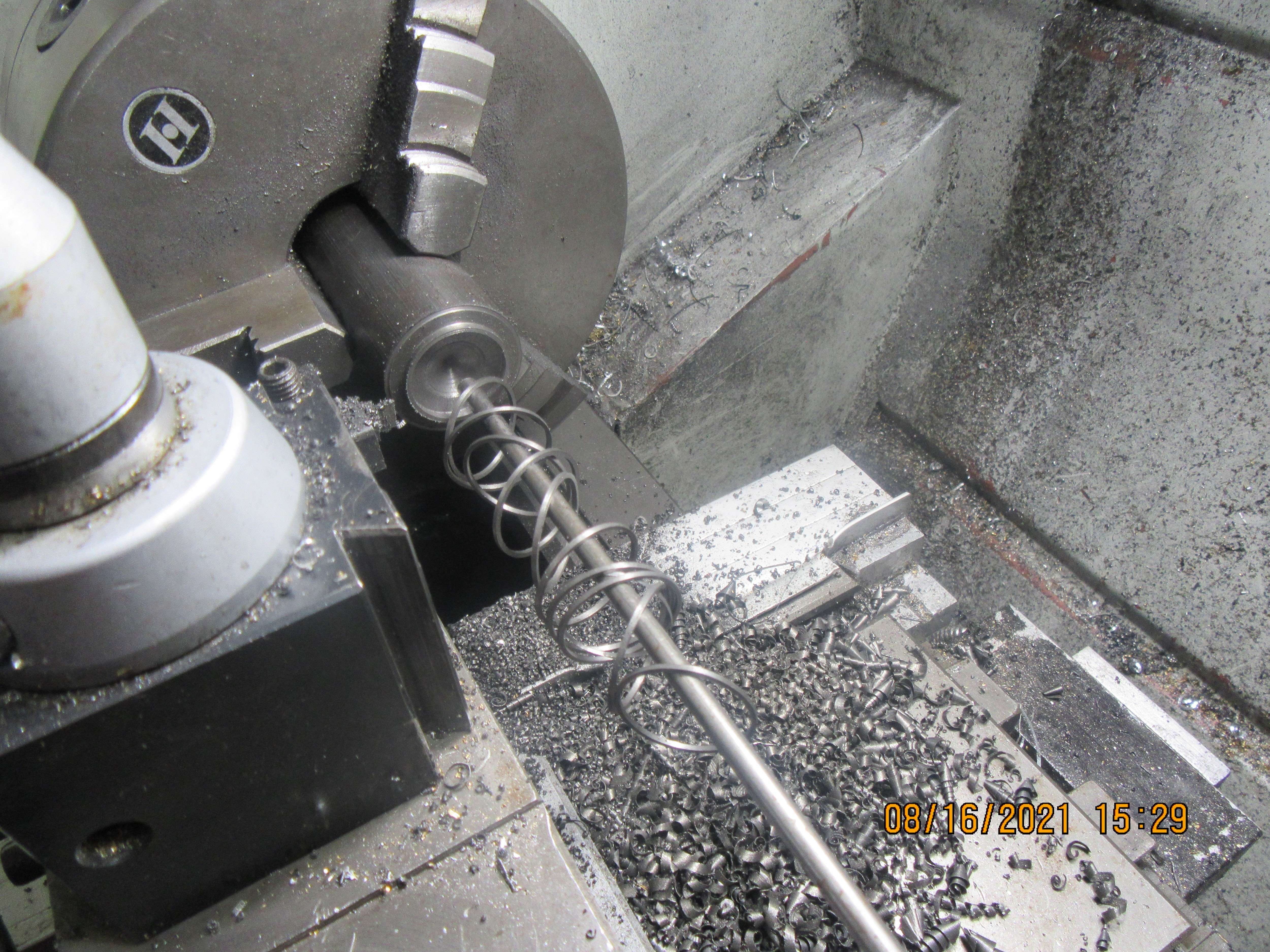
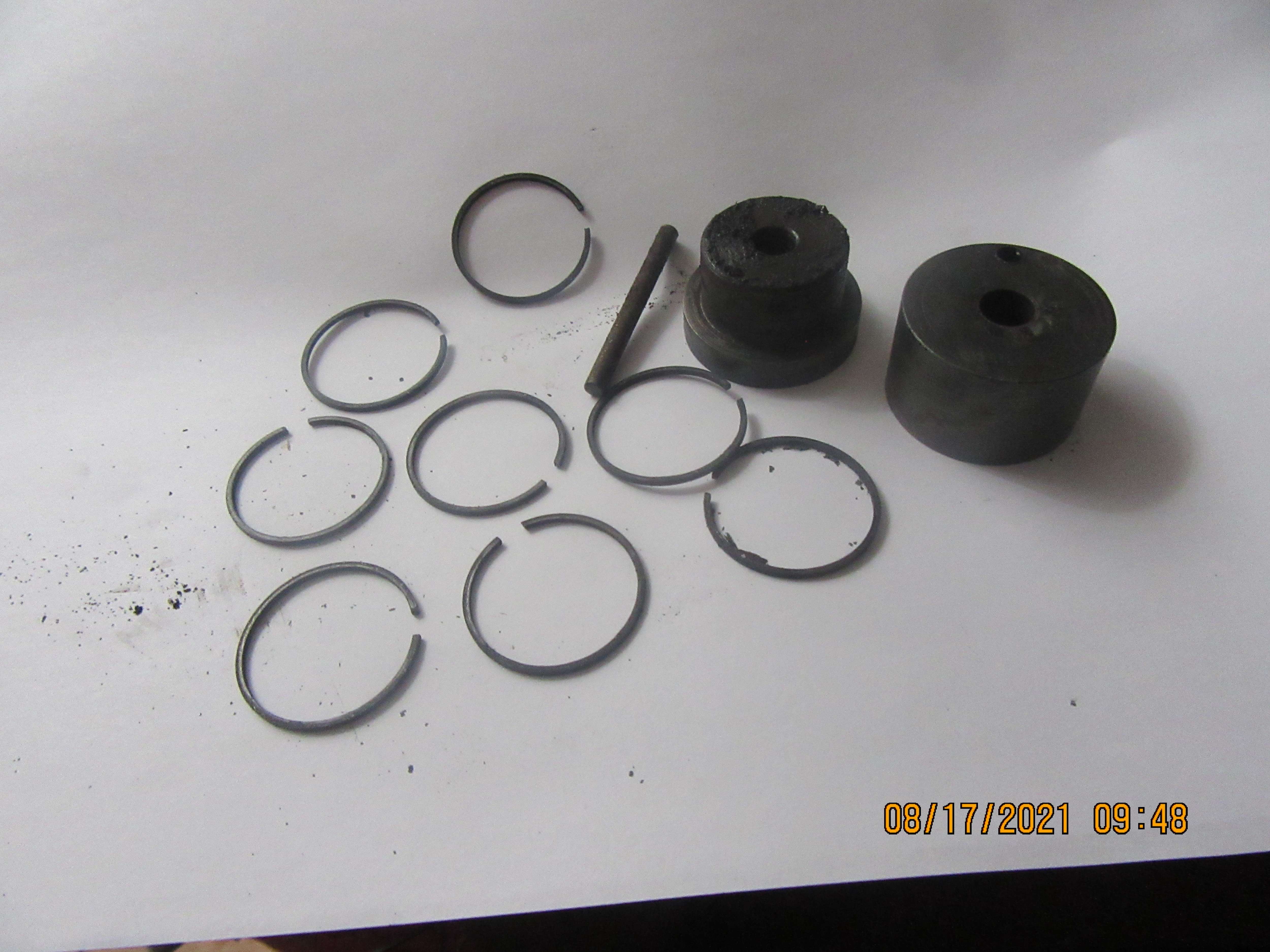
Okay, here's what we've got going. Thats a piece of 1 3/8" diameter grey cast iron in the chuck. The o.d. is turned down to the diameter of the cylinder, not the piston. My rings are going to be .038" (1 mm) thick radially so the inside is drilled out to 0.925" diameter. The o.d of what will become the rings is polished with a fine whet stone, or a piece of 400 grit paper backed up by a file or piece of flat-bar. This time my rings are going to be 0.045" thick, and my specially ground cut off tool is 0.038" wide, so .045 plus .038 plus .003" to have a bit extra length equals 0.086", so thats how far I advance the carriage before taking another cut. The rod held in the tailstock chuck is something to catch the rings as they are parted off. I have to remember that each time I cut a ring off, I have to deburr the outside and inside diameter of the piece held in the chuck, so that at least one side of the ring is deburred.---It is remarkably easy to forget that step. Each ring will now be measured with my micrometer to make sure it is the right thickness, and then held in a fixture with a 0.020" deep x 1" diameter recess. It is then slid around in a figure 8 on a piece of 600 grit paper until it reaches the magic 0.045" thickness. Then it is fitted into the piston ring groove to make sure that it actually will go down to the bottom of the groove. My chuck has about 0.003" total indicated runout, so I cut off a bunch of rings while in this set up, because if I take that piece of round stock out of the chuck, I will never get it back in the same spot, and I don't want to make rings that are not truly concentric.
eD1eKu.jpg
Chamfering of the BACKSIDE of the rings is demonstrated by Mr. Crispin using a "trumpet chamfering tool" in his very well done video;


The application and the processes are different but the techniques are still applicable.
His tool & cutter grinder and profile projector could be replaced in a pinch with a Dremel tool, a steady hand, and a hand lens to check the progress.
Trepanning the stock rather than reducing it to dust is another interesting variation in the process.
Congratulations on the successful rings!

Best regards,
Larry
 
Skyline1--Cast iron rings are something new for me. I have about twenty engines running Viton rings because they are fast, easy, and work very well in most cases. I have tried and failed to make proper cast iron rings in the past, so this summer I spent considerable time and effort making cast iron rings that work. I learned a lot, and am still in the learning process.---Brian
 
Yes it's quite a process and not always successful I believe

I had the opportunity to visit Welworthy Piston Rings in the U.K. many years ago, where they make piston rings from tiny little ones to huge monsters for marine engines and the like. I found the process both fascinating and a little intimidating. Their heat treatment plant was amazing !

Such is the difficult nature of making them that even Welworthy with many years of experience have a high scrap rate on small ones (up to 50% IIRC) so you are not alone in losing a few along the way.

Out of interest, I found out during this visit, that the really large ones need to be specially supported during transport and fitting because until they are safely in their grooves they can actually break under their own weight.

So congrats on your ring success any I hope your flywheels turn up soon It will be nice to see the first run soon

Best Regards Mark
 
Do you ever measure the horsepower or torque output of your engines?
 
Chamfering of the BACKSIDE of the rings is demonstrated by Mr. Crispin using a "trumpet chamfering tool" in his very well done video;


The application and the processes are different but the techniques are still applicable.
His tool & cutter grinder and profile projector could be replaced in a pinch with a Dremel tool, a steady hand, and a hand lens to check the progress.
Trepanning the stock rather than reducing it to dust is another interesting variation in the process.
Congratulations on the successful rings!

Best regards,
Larry

That is a very interesting take on making and heat treating rings. The trepanning could be replaced by just doing a final bore. I wonder how his heat treating fixture performs compared to the Trimble fixture.

I have been remaking some rings using the Trimble method and I have not been too successful. If I put the finished ring in the bore and shine a light I seem to be able to see light almost all of the way around with only a few spots actually tight against the bore. Also the rings seem to vary .002 in thickness both before and after rubbing them on wet/dry sandpaper. He uses oil on the sandpaper. I wonder if that would make a difference.
 
No, I never do a HP test on my engines. The best result for me is that the engines run!! I have thought about making a device to measure horsepower, but it's not something that I really feel like building.
 
The best result for me is that the engines run!!

Seeing something run under it's own power that you have built (and in your case designed) yourself is a great satisfaction.

I think you, like myself, also enjoy the development and evolution that can come from initial poor results or even outright failures ( I've had many)

In small scale engineering like this things often don't work out quite as the accepted rules say they should. With so many square and cube laws involved our machines are often quite different from full size, and Model Engine builders have developed some very strange techniques indeed to achieve the desired results.

Do you ever measure the horsepower or torque output of your engines?

To some just seeing them work is quite sufficient, they are not interested in the cold, hard, mathematics of horsepower and efficiency but others are quite interested in these things. "each to their own" such is the nature of this hobby it spans quite a range of activities and interests.

Small scale "model" Dynamometers are quite feasible at this scale and actually fairly straightforward to build, there are a number of designs online I found this one quite interesting dynamometer (friction torque meter) by zhwang168

I worked with old "swing frame" electrical Dynos at one time and have often thought of making a working model of one.

Best Regards Mark
 
Today has been a day of cleaning, sanding, and chasing down tight spots. I am always somewhat amazed at how much dirt these little engines make in the final moments of assembly prior to running. A ton of grey sludge seems to come off all of the aluminum parts and even from the cast iron parts. Today I installed the gasket that fits between the two halves of the crankcase and the gasket that fits between the top of the crankcase and the underside of the cylinder assembly. Tomorrow I will make the head gasket and probably make a gasket to put between the cylinder top plate and the cylinder body itself. I haven't heard a peep from the folks at Martin Model about shipping my flywheels, but I see that they have put the charge on my Visa. in a perfect world, I would receive the flywheels before I finish everything on the engine, but it's getting tight. I will set the ignition and valve timing tomorrow, and then there really isn't anything left for me to do. (I say that with tongue in cheek, because I never know until the very last minute if my valves are going to seal or not).
 
Years ago, you paid for goods when received... COD. But plastic cards and computers are designed so you pay instantly, so a bank or other can have you money invested for days before the payment gets to the recipient... and before you get your goods.
Ho hum....
K2
 
Actually I phoned the guy yesterday to see what was going on with my flywheels. They had been shipped out on the 8th of august, but nobody had let me know.
 
All right!!! Engine is timed, both valves and ignition. I didn't use a degree wheel. I set my crankshaft at whatever angle I want in my 3D program, then measure down from the top of the cylinder to the top of the piston. Then I set my vernier for that distance, turn the engine by hand in the correct direction until the piston touches the depth gauge end of the vernier. Then I loosen off the screws in the crankshaft gear on the side I am timing and rotate it until the valve just begins to open (this is quite visible because the cylinder head is removed). Ignition timing is set to about 5 degrees before top dead center. I always go a little crazy doing the timing, because I have to remember which side I am putting the starter fixture on, and then remember which side of the engine I'm working with and knowing that on the far side of the engine the crankshaft will be rotating in the opposite direction.
 
What an explanation Brian. I was expecting you to say you determined the valve opening by cam because you had a Pipe connected and blew on it till you could feel the pressure drop when it opened! Or a DTI on the valve head...
I used to do the ignition timing on my Yamaha motorcycle with a DTI + extension down the plug-hole to piston crown. The book said it should be fully advanced and fire at 1mm Before TDC. Easy!
K2
 
Today I milled keyways into both ends of the crankshaft, finished making gaskets, and mounted the cylinder head and sparkplug. At this point, turning the engine over be hand, I can't really tell if I can feel compression or not. That is not unusual, because my new engines are a bit stiff. Tomorrow we are having a family birthday party for my second oldest granddaughter who is turning 14 and my mother who is turning 101. There isn't much more that I can do to the engine now until my flywheels come.---Brian
 
Today I milled keyways into both ends of the crankshaft, finished making gaskets, and mounted the cylinder head and sparkplug. At this point, turning the engine over be hand, I can't really tell if I can feel compression or not. That is not unusual, because my new engines are a bit stiff. Tomorrow we are having a family birthday party for my second oldest granddaughter who is turning 14 and my mother who is turning 101. There isn't much more that I can do to the engine now until my flywheels come.---Brian
HAPPY BIRTHDAY to your mother Brian, that is a milestone that not many of us ever reach. Hope she is well and enjoys the party.
John
 
Back
Top