Gordon--my gaskets are never very complicated. Since I have the parts which need gaskets in 3D cad, I just print them out at one to one scale and glue them to a cardboard cereal box or to a roll of 0.030" waterpump gasket. I have a leather punch here on which I can select the hole size I want for bolt clearances, and I have made a lot of my own different larger punches. Everything else gets cut out with a pair of scissors or a scalpel.

You are using an out of date browser. It may not display this or other websites correctly.
You should upgrade or use an alternative browser.
You should upgrade or use an alternative browser.
T head engine by Brian
- Thread starter Brian Rupnow
- Start date


Help Support Home Model Engine Machinist Forum:
This site may earn a commission from merchant affiliate
links, including eBay, Amazon, and others.
Gordon
Well-Known Member
- Joined
- Jan 4, 2011
- Messages
- 1,333
- Reaction score
- 344
I am not sure about 3 or 4 but it is a Portrait model. I just use standard automotive gasket material. Usually 1/32 thick or sometimes .015. I have used Teflon also. Any of them require cutting 2 or 3 times. Just restart without removing the material.Sorry if you covered this before, I am intrigued about the Silhouette Plotter
Did you get the 3 or 4 model and what material do you use for gaskets?
Thank you.
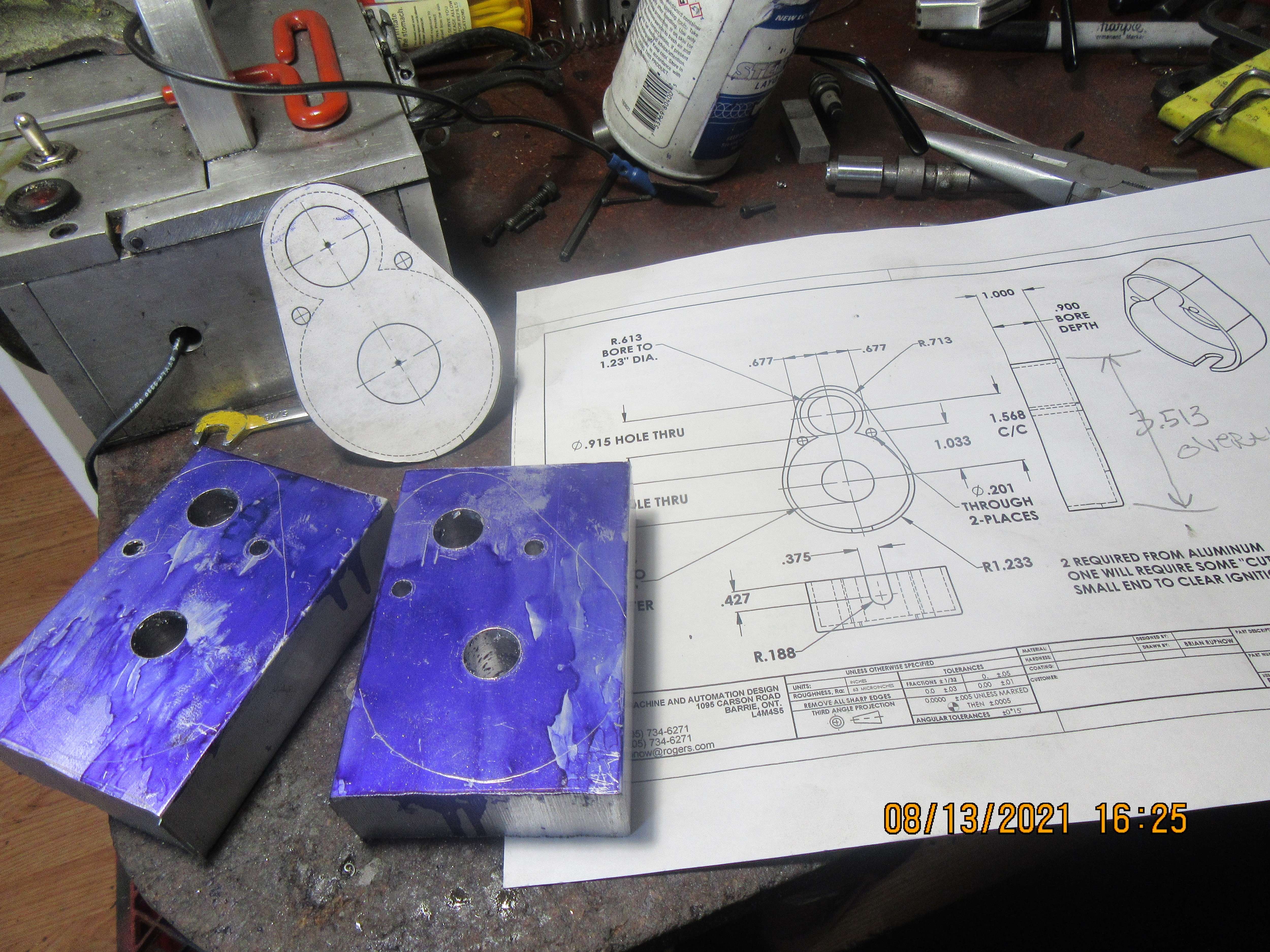
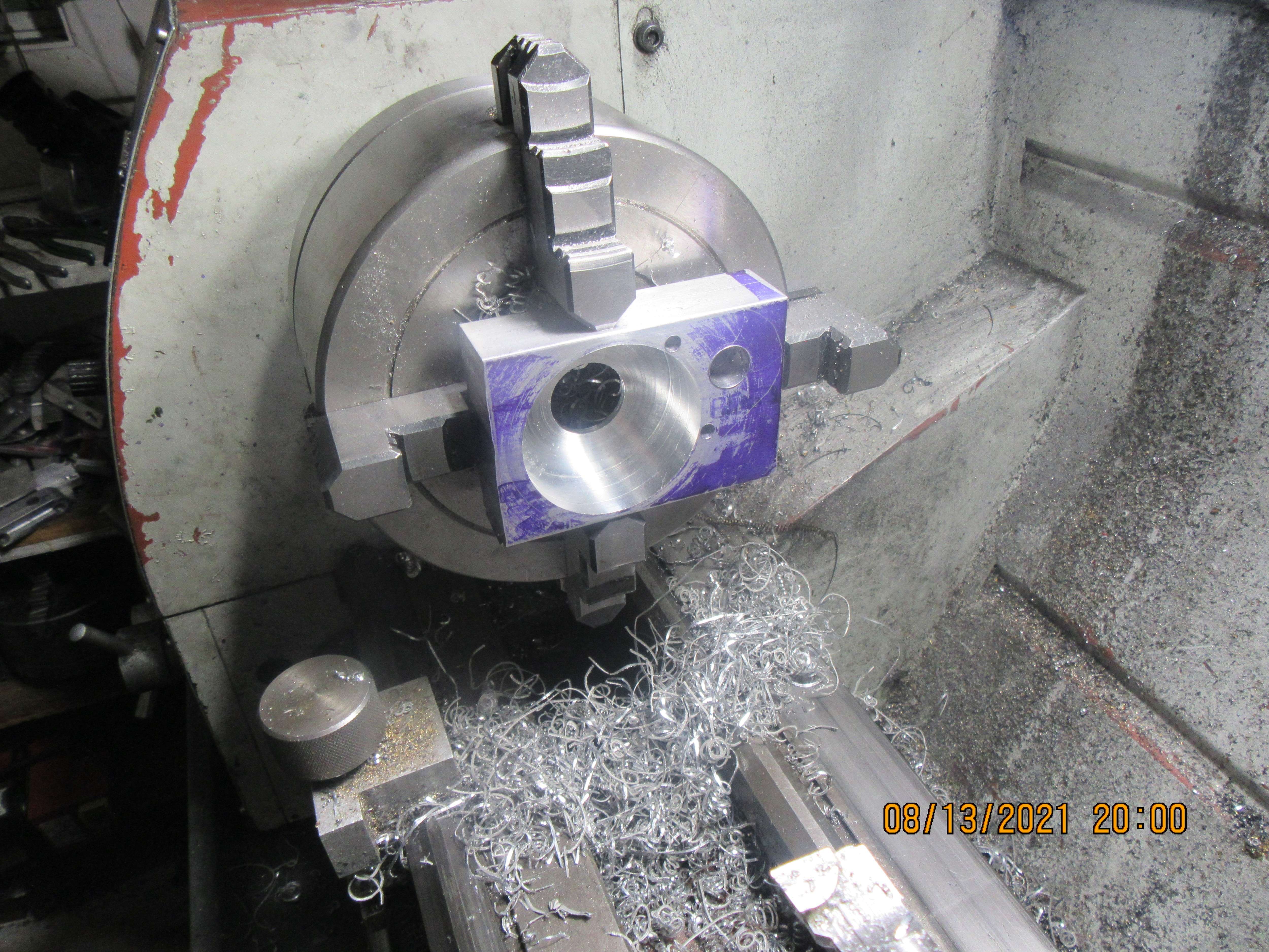
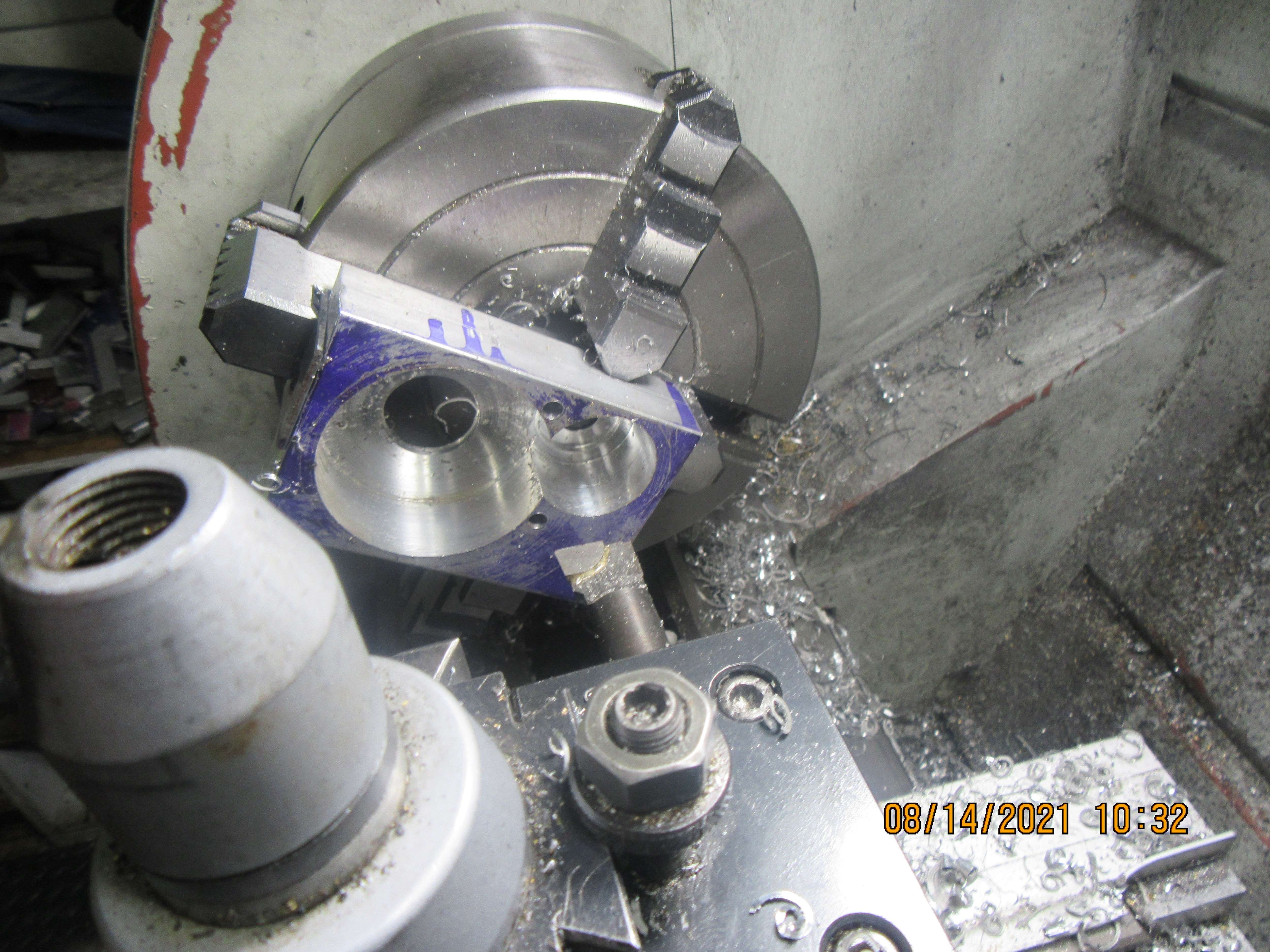
Decided to get up off my lazy butt and actually do something this afternoon. I purchased some 2 1/2" x 1" aluminum bar, cut it to two lengths, laid the outline on it with a template, then set it up in my milling vice and used the DRO to position things accurately. The template helps me figure out what I'm doing, and gives me a visual check, to see if my DRO is giving me the same information. The 0.201" bolt holes were drilled and a 1/2" drill ran thru at the appropriate centers. Next trick will be to mount the pieces one at a time in the four jaw lathe chuck and bore the blind cavities that the gears fit into as well as the thru holes where the gear hubs stick through.
skyline1
Well-Known Member
- Joined
- Aug 6, 2012
- Messages
- 438
- Reaction score
- 147
So the basic answer is, turn the handle 1 & 5/13 times per tooth ... but you don't have a 13 index, you have a 39 index. No problem: multiply the fraction by 3/3: 5/13 * 3/3 = 15/39. So now you have your final answer: set up the sector arms to allow a movement of 15 holes on the 39 hole index. (The sector arms will span a total of 16 holes - 1 for the pin to start in, and 15 more for it to move). For each tooth, make one complete revolution plus 15 holes as indicated by the sector arms, then reset the sector arms. Cut, rinse, repeat.
Thanks Awake 1 turn and 15 holes on a 39 hole plate exactly the same answer as I got. The key to this is that 39 is 13 x 3 so for every 1 hole you would go on a 13 hole wheel you go three holes on a 39 hole.
Brian, well done on the incredible speed at which you are building this engine, It's almost ready to run now in a matter of weeks, an amazing feat, I wish I could do things that fast
Best Regards Mark
Realistically, if you don't have the dividing plate you need one could print the required 'plate' and paste it on an existing one and make a new one, it would take a little care because there are no holes but the gear reduction would reduce the error on the generated plate.Thanks Awake 1 turn and 15 holes on a 39 hole plate exactly the same answer as I got. The key to this is that 39 is 13 x 3 so for every 1 hole you would go on a 13 hole wheel you go three holes on a 39 hole.
Brian, well done on the incredible speed at which you are building this engine, It's almost ready to run now in a matter of weeks, an amazing feat, I wish I could do things that fast
Best Regards Mark
Brian, you really do move with your builds!
skyline1
Well-Known Member
- Joined
- Aug 6, 2012
- Messages
- 438
- Reaction score
- 147
Realistically, if you don't have the dividing plate you need one could print the required 'plate' and paste it on an existing one and make a new one, it would take a little care because there are no holes but the gear reduction would reduce the error on the generated plate.
That gives me an idea !
I wonder if I could 3D print a plate, I could have any number of holes I wanted and my 3d printer is pretty accurate,
The plastics used in 3D printing are remarkably tough and resilient I have made many "real" structural components with one. Has anyone tried it ?
I might even be able to 3D print the actual bull wheel, I have heard of people making replacement gears for minilathes by this method and plastic gears are increasingly being used nowadays.
Best Regards Mark
First I bore the blind hole for the big gear---then I bore the blind hole for the small gear. Then after much sanding, filing, and sanding some more I have an awesome set of gear guards.
I've done 3d printed change gears for my Sheraton lathe (needed for cutting metric threads) and template for the indexing fixture of my Atlas mill. I cut the gears for my Webster using the 3d printed template gears and they worked perfectly (even wear on all the teeth after running). The change gears aren't so great, the teeth hold up fine but the keyways of the stud gears soon get damaged due to the plastic being too soft.That gives me an idea !
I wonder if I could 3D print a plate, I could have any number of holes I wanted and my 3d printer is pretty accurate,
The plastics used in 3D printing are remarkably tough and resilient I have made many "real" structural components with one. Has anyone tried it ?
I might even be able to 3D print the actual bull wheel, I have heard of people making replacement gears for minilathes by this method and plastic gears are increasingly being used nowadays.
Best Regards Mark
skyline1
Well-Known Member
- Joined
- Aug 6, 2012
- Messages
- 438
- Reaction score
- 147
I'm 3D printing an experimental plate to try but I don't want to hijack the thread so if it is successful I will open a new thread about it with some pictures and the STL file.
Brian It looks like you have only the flywheels left to do. What kind of ignition do you intend to use ?
Best Regards Mark
Brian It looks like you have only the flywheels left to do. What kind of ignition do you intend to use ?
Best Regards Mark
Same 1976 Chrysler points and condenser----same as I always use.
I have been using the Silhouette cutter for many years. Originally using Design Master as the interface between dxf and the Silhouette but unfortunately this no longer works due the licencing and obsolescence. Using dxf with Studio Design was a real pain. I tried Inkscape with little success. The main problem with Studio and dxf is scaling but there are commands to change the scaling. There are other issues so I generated the procedure below which I find works. It is based on surrounding the required shape in a box of known size in AutoCAD or other dxf apps. I then scale the drawing in Studio so that the box is the correct size.Sorry if you covered this before, I am intrigued about the Silhouette Plotter
Did you get the 3 or 4 model and what material do you use for gaskets?
Thank you.
Happy to provide more info.
If anyone has a better method, I would love to hear about it!
- Cutter – Silhouette SD from eBay
- Silhouette Studio Design Edition version 4.1
- Create dxf file in AutoCAD 2000 format – this is my default format for greatest flexibility.
- DO NOT JOIN lines – if joined expand. (If joined the cutter makes many small cuts)
- Make sure there is a box around object of known size in inches
- In Studio Designer File/Open/select file – takes time to load
- Using arrow in top left corner select box and content
- Right click object and select - Make compound path
- Open transform panel – 3 vertical lines on RH menu
- Double click to Select the 45deg line (takes time)
- Close padlock
- Type the correct width of the box into one of the boxes and click the second box to see the new value, apply
- If necessary, move object using the single up/down/left/right arrows
- Select Send and then send. Cutting lines are in Red
- For thin card set to single cut, for gasket material 0.25mm select 2 cut. Use FLEXOID Gasket Paper 0.25 thick – from eBay
Gordon
Well-Known Member
- Joined
- Jan 4, 2011
- Messages
- 1,333
- Reaction score
- 344
I just load the DXF file and highlight it which shows the various dimensions. Pick some know dimension and rescale the file. For instance if something which should be 2" shows as 2.2" just resacle the entire drawing to 2.2/2 and check to make sure that it is correct. I am not sure why but it is not consistent. Sometimes it is oversize and other times it is under size. On one file 2" may show as 2.2 and the next time 2" may show as 1.9". I have been told that there is some setting which automatically corrects this but I have not found it and it is not important enough to me to spend the time finding the secret. I just always rescale. Always use a mat and keep notes on what worked unless you use it often enough to remember every time. I mainly use it for gaskets so it can be weeks between uses.I have been using the Silhouette cutter for many years. Originally using Design Master as the interface between dxf and the Silhouette but unfortunately this no longer works due the licencing and obsolescence. Using dxf with Studio Design was a real pain. I tried Inkscape with little success. The main problem with Studio and dxf is scaling but there are commands to change the scaling. There are other issues so I generated the procedure below which I find works. It is based on surrounding the required shape in a box of known size in AutoCAD or other dxf apps. I then scale the drawing in Studio so that the box is the correct size.
Happy to provide more info.
If anyone has a better method, I would love to hear about it!
Note that 1 cut is the default
- Cutter – Silhouette SD from eBay
- Silhouette Studio Design Edition version 4.1
- Create dxf file in AutoCAD 2000 format – this is my default format for greatest flexibility.
- DO NOT JOIN lines – if joined expand. (If joined the cutter makes many small cuts)
- Make sure there is a box around object of known size in inches
- In Studio Designer File/Open/select file – takes time to load
- Using arrow in top left corner select box and content
- Right click object and select - Make compound path
- Open transform panel – 3 vertical lines on RH menu
- Double click to Select the 45deg line (takes time)
- Close padlock
- Type the correct width of the box into one of the boxes and click the second box to see the new value, apply
- If necessary, move object using the single up/down/left/right arrows
- Select Send and then send. Cutting lines are in Red
- For thin card set to single cut, for gasket material 0.25mm select 2 cut. Use FLEXOID Gasket Paper 0.25 thick – from eBay
Hey Guys---Please start your own thread to discuss things that are not related to this engine build.---Brian
Gordon
Well-Known Member
- Joined
- Jan 4, 2011
- Messages
- 1,333
- Reaction score
- 344
My sincere apology. I had no intention to hijack your thread. I will be more cautious in the future.Hey Guys---Please start your own thread to discuss things that are not related to this engine build.---Brian
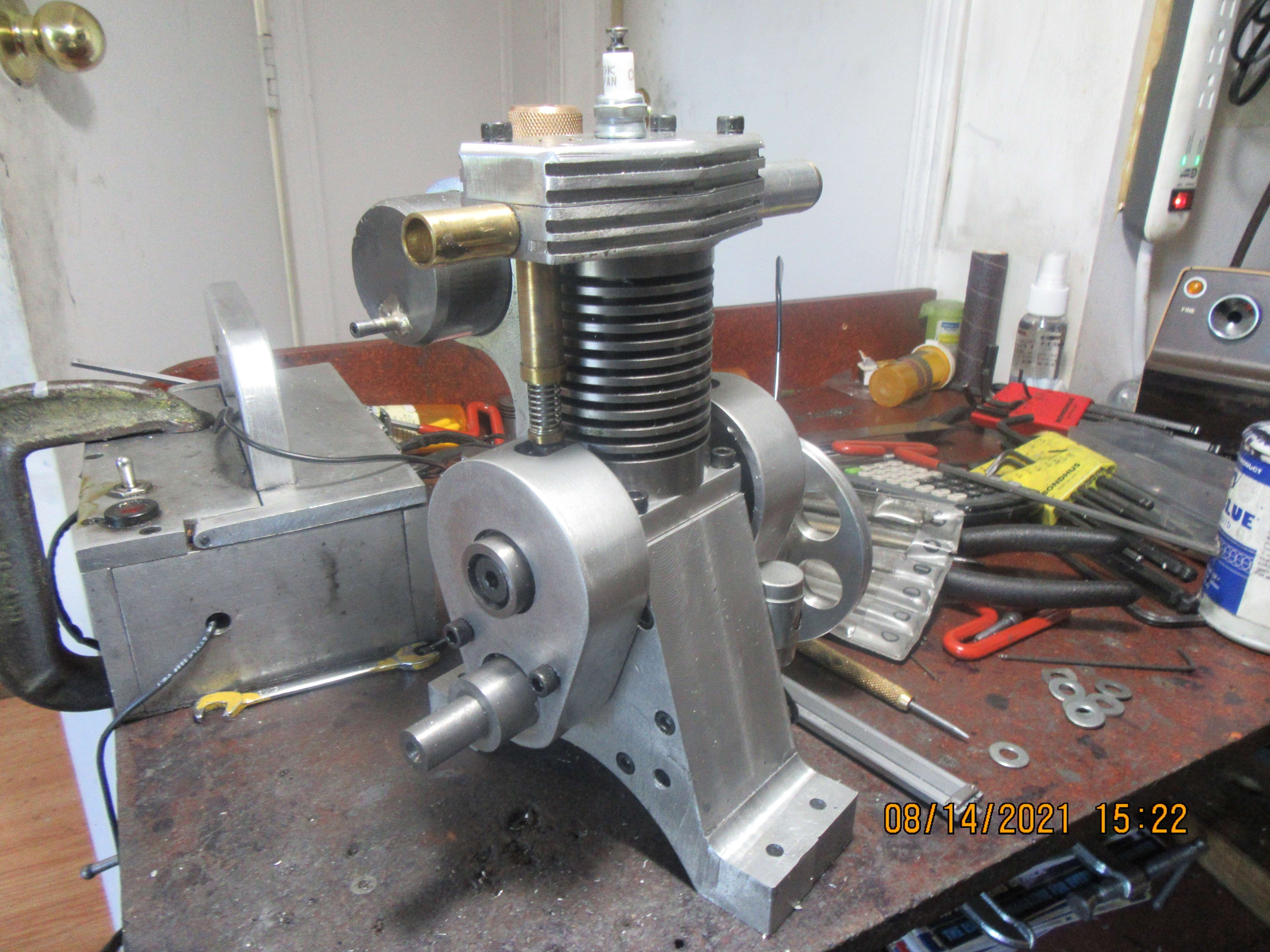
Gordon--that wasn't aimed at you. The gear guards certainly will protect fingers. Oddly enough, that's not the real purpose I put them on there. I find that exposed spur gears make a terrible lot of noise. It seems that if they have a guard made of brass or aluminum (not sheet metal) around them, it quiets them down a lot. and they certainly make the engine look more robust. I am now at the point where I have nothing left to make except the cast iron rings. Earlier this year I did a thread on making my own cast iron rings. There was a great deal of trial and error, but I finally did successfully make a set that worked very well on one of my 1" bore engines. I made a lot of notes about what I did, and I still have all the fixtures I used. This engine is also a 1" bore, so I'm hopeful that I learned enough from my previous ring making exercise to do it again. I'm still waiting to hear from the flywheel people---they are supposed to contact me when the rings are shipped.
Okay, here's what we've got going. Thats a piece of 1 3/8" diameter grey cast iron in the chuck. The o.d. is turned down to the diameter of the cylinder, not the piston. My rings are going to be .038" (1 mm) thick radially so the inside is drilled out to 0.925" diameter. The o.d of what will become the rings is polished with a fine whet stone, or a piece of 400 grit paper backed up by a file or piece of flat-bar. This time my rings are going to be 0.045" thick, and my specially ground cut off tool is 0.038" wide, so .045 plus .038 plus .003" to have a bit extra length equals 0.086", so thats how far I advance the carriage before taking another cut. The rod held in the tailstock chuck is something to catch the rings as they are parted off. I have to remember that each time I cut a ring off, I have to deburr the outside and inside diameter of the piece held in the chuck, so that at least one side of the ring is deburred.---It is remarkably easy to forget that step. Each ring will now be measured with my micrometer to make sure it is the right thickness, and then held in a fixture with a 0.020" deep x 1" diameter recess. It is then slid around in a figure 8 on a piece of 600 grit paper until it reaches the magic 0.045" thickness. Then it is fitted into the piston ring groove to make sure that it actually will go down to the bottom of the groove. My chuck has about 0.003" total indicated runout, so I cut off a bunch of rings while in this set up, because if I take that piece of round stock out of the chuck, I will never get it back in the same spot, and I don't want to make rings that are not truly concentric.
We're up, up and away!! I managed to harvest ten rings. They were all deburred both sides, and the faces were sanded on 600 grit paper attached to a cast iron surface plate until they were 0.045" to 0.043" thick. They were all spread over a .150" diameter pin and sandwiched and clamped between two sides of a heat treat fixture. They are now in my heat treat oven, soaking at 1100 degrees for three hours. I decided that I didn't really like the "cleaver" that Trimble designed and I built, because it seemed to bend the rings a bit when it cleaved them. I ended up using a sharp cold chisel to "break" each ring, then filed the ends with a points file until they had the correct 0.004" end gap when installed in the cylinder.
Hi Brian, I am curious to know if the radial force of the ring on the bore is "just a feather more than contact", a "real spring pressure" or moderately between? I.E. what is the gap outside the bore (I can't guess?), and you use 0.004" gap when fitted in the bore? (I would guess about 0.001" per 1" of bore, so ~0.001" for your 1" bore engine? I would have expected 0.004" on a 3 ~ 4" bore engine?). Modern car engine thinking is that the minimum radial force is all that is needed as the rest of the working contact pressure comes from gas pressure acting at the back of the rings during compression and firing strokes.
- Except for oil wiping rings, that need higher initial pressure (and the contact point is exceedingly narrow to achieve that) to break the oil film and wipe to the bore's apparent surface. (I.E. all the microscopic high spots on cross-hatching).
But I don't know what is best for models like yours?
Keep up the excellent work!
K2
Oh, another item (It takes the brain a few moments to think of the second question!): You talk of the Trimble "cleaver" causing some distortion at the cut? Is this "curling inwards"? Not knowing the Trimble tool's direction of "cut", it sounds like you are talking of distortion to the curvature of the outside diameter, next to the ring gap? I would have imagined a "cleaving hit" - as with a cold chisel - to be applied with the ring resting on a surface plate as the anvil, and the striking face being a flat face that is either the top or bottom face of the installed ring. (I would put it on the bottom face - at a guess? - but I can think of alternative reasons for this to become the top face?).
But maybe my imagination is on the "wrong planet" for your explanation?
Thanks,
K2
But maybe my imagination is on the "wrong planet" for your explanation?
Thanks,
K2
Similar threads
- Replies
- 413
- Views
- 39K
- Replies
- 148
- Views
- 20K
- Replies
- 61
- Views
- 8K
- Replies
- 7
- Views
- 2K