Super Tigre G32 1cc diesel - a 5cc version

Home Model Engine Machinist Forum

Help Support Home Model Engine Machinist Forum:

This site may earn a commission from merchant affiliate links, including eBay, Amazon, and others.
Hi Ramon

Your work is just beautiful; thank you for taking the time to post the pictures and descriptions. I have been enjoying your build so far and I'm always looking forward to an update.

I do have a question though; what is the propose of the inner shaft on the crank?


Thanks,
Dave
 
Nice Ramon!

NICE FIXTURES! your work is great as usual!

GailNM did a write up or should I say was written about for his version of the shaft hone in Model Engine Builder.....Nice unit.!

Dave
 
Hi Guys, thanks for your comments - it's good to hear from some of you and pleased to note this is helping in some way.

Dave(Idahoan) Theres no real purpose as such but the reasoning goes back to my first engine build - the Nova. At that time, when it came to the crankshaft the only piece of En24T that I had was big enough to do one shaft but if done as described above was enough to get two out of if something went wrong. As it happened it didn't so I had a spare bit. I felt that the steel a high tensile bolt was probably suitable for the task and hence the method was born. I later scrounged some offcuts of En24T but to conserve them have continued with this method which so far appears to have stood up to the forces well. I'm not sure if I made it clear but the major part of the shaft is reamed for a size slightly larger than the front of the shaft finishes at ie in this case 7mm to finish 6.35mm -.250". Carrying out the finish turning between centres eliminates any slight discrepancy of the two parts.

Dave (Steamer) I saw the external hone article in MEB and had it earmarked it as a project. I had just missed out on some external hones on Ebay just before the article was published so was quite keen to make a set. However another two sets of hones, sold as one item, appeared a bit later and this time I was successful. Described as used and missing a screw :eek: and allen key :eek: :eek: imagine my surprise when they arrived to find they had never been used and were still covered in the maufacturers grease. Not a single stone or guide in either set had a mark on it. With no manufactures name on the cases I was beginning to think they may be eastern copies but no there was a raised 'delapena' hidden under that crackle finish on the arm and yesterday, when I cleaned that grease off I realised the clamp screw has all the details engraved on it. ;D. I used them again today to reduce the drum valve - can't wait to try them on the pistons ;)

Don, as Dave says on his Wallaby thread using a faceplate is a really good facility that some seem to forget about. It's a very versatile piece of kit and can cope with all kinds of set ups. I was hoping to show a couple of pics of something very simple but which is so very useful on the faceplate but I ran out of time tonight having only just finished the drum valves but I'll take some pics tomorrow.

Had a good session in the ole shop today heres a few more pics of progress....

After the crankpins were turned it was time to tackle that awkward bit of milling the crank web away. Awkward more in the means to hold it and align the crankpin true but having got the whole thing this far it's still a bit of a fraught time until the op is over - well it is for me ;)
It was gripped in the turning fixture itself held in the vise and the pin aligned by bringing a tapered spigot the same diameter as the crankpin down into the centre then the two could be aligned by a square off the back column
DSCF0368.JPG


The milling was carried out in very tentative .5mm depths of cut before finishing the sides of the cut outs
DSCF0375.JPG


DSCF0407.JPG


The drum valves were turned from silver steel as these will need to be hardened at least on the disc where the drive is picked up. Straightforward turning and boring they are nothing more than top hats. They do need the inlet aperture milling in accurately to the crankpin hole however so another simple fixture was quickly made

Just a piece of flat BMS bar, obviously used for several other ops on parts in the past had two holes put in - one to locate the spigot bolted on, the other to accept a removable peg. (Yes, I did deburr the hole ;))
DSCF0383.JPG


The valve was located over the spigot and aligned at the 42degrees called for and the vise tightened before removing the pin
DSCF0389.JPG


The table stops were set for a 3mm cutter and the slot cut out using a 2.5mm cutter first to rough and then the 3mm to finish. The burrs look terrible - it's silver steel after all - but actually they removed very easily without any effect to the finished surface
DSCF0393.JPG


Finished ready for heat treatment tomorrow hoping like hell that they dont distort!
DSCF0400.JPG


Next up is to make a couple of laps to settle in the shafts and valves to their sleeves and make the prop driver and collet to finish off the 'bottom end'

Regards for now - Ramon


Hi guys, had a good day in the shop today, door open, sun shining in for a while, birds singing, tea on the go - ahh retirement ;D

Kicked off by taking a look at lapping out the sleeves. All of the laps made over the years save one have been copper and to the same design - more on them when the liner is tackled but they are fully adjustable and can be slacked off within the workpiece.
The odd one - I have no idea what it was made for but it was done in a hurry - looked like this and due to the design is basically 'one way' only
DSCF0411.JPG

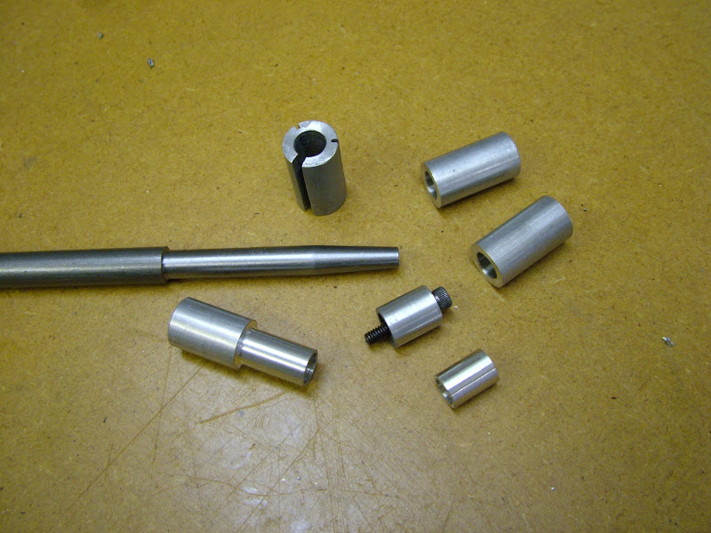
Its a split aluminium lap tapered inside to match the mandrel which is 3/8 MS. The other day whilst rooting in some boxes I found the tapered reamer I'd made at the same time for the laps and I began to wonder if this could be improved to prevent the possibilty of over expanding and galling in the bore particularly on the drawn phos bronze about to be tackled. :idea:.
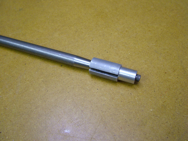
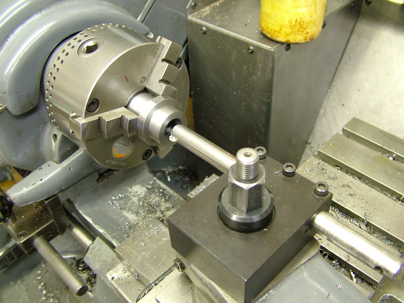
I turned the mandrel down and made a short sliding sleeve that would allow the part to pass over it but would allow the mandrel to be pushed out of the lap by slackening the screw, releasing the collet and applying pressure to the screw with the tailstock. It works great and opens up the possiblities for much easier to make laps that the copper ones made so far and ceratinly eases that fear of jamming the lap in the bore.

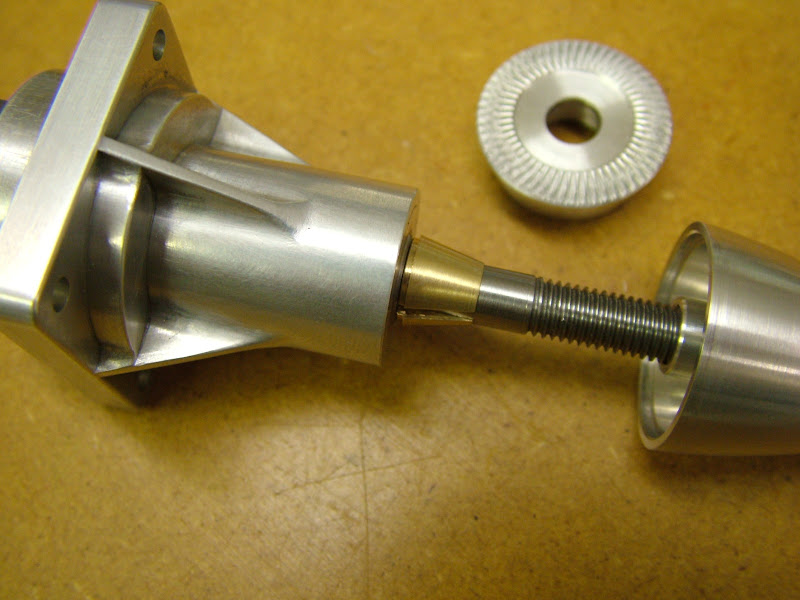
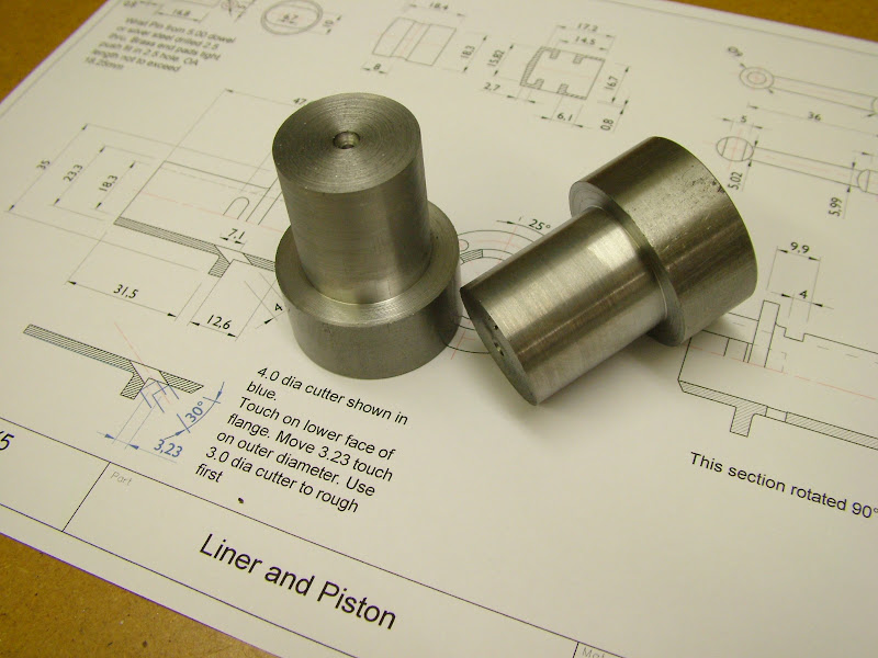
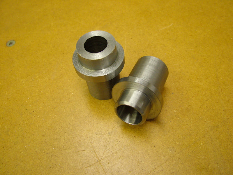
Sleeve is bottom left, original lap at top. (The grooves are not for holding paste but for easing the expanding pressure) and two internally tapered blanks for the laps.
DSCF0415.JPG


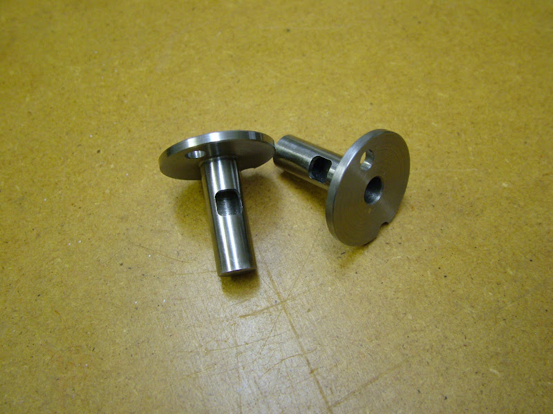
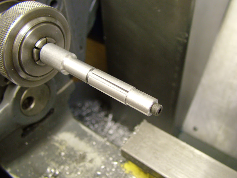
Held on the mandrel the blanks were turned down to with .5mm of their finished size, removed and split on the mill then returned for turning to finished size such that the part would slip easily over the lap. This is the first lap finish turned and ready to use.
DSCF0418.JPG


600 grit silicon carbide powder mixed with a little oil was used and though grades to 1000 are there to use the finish was more than acceptable and was left as sized.
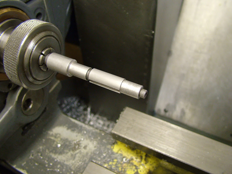
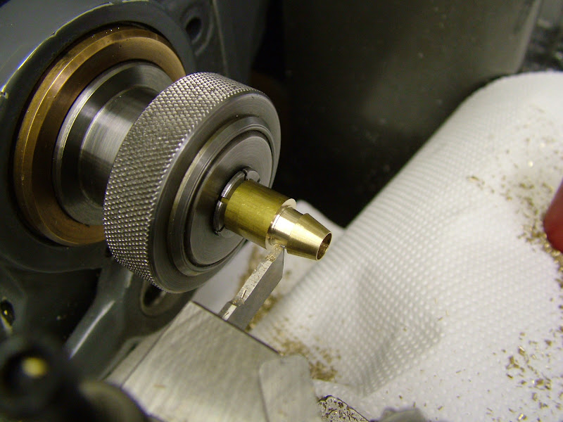
The lap was liberally coated with the paste and, with the lathe still stationary, the part pushed over working it to get the paste evenly distributed. The lap was then tightened until a reasonable resistance was felt, and the lathe started up at about 2-300 rpm ( have no idea of the exact speed as its variable speed). The rear valve sleeves took very little time to bring to size 20 - 30 mins but the main bearings which had .05mm to come off took quite a bit longer
DSCF0421.JPG


The lap should exhibit a nice uniform matt appearance if working properly
DSCF0425.JPG


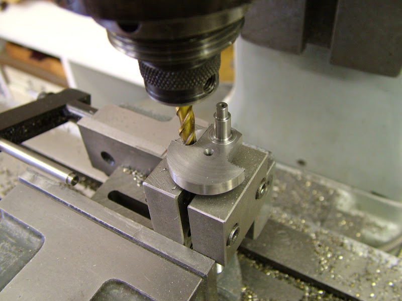
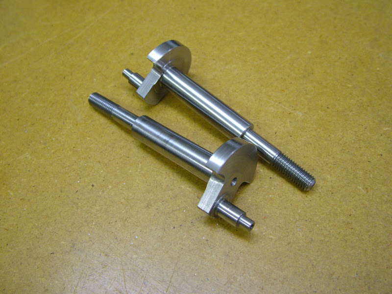
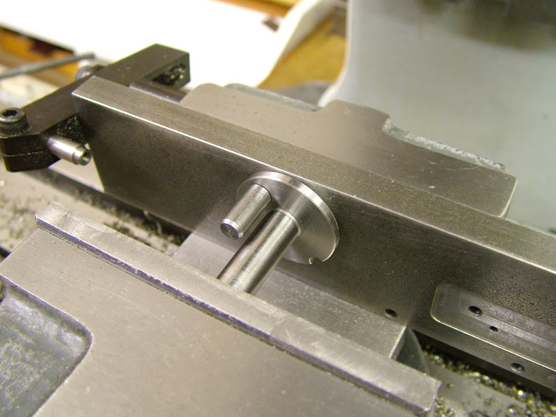
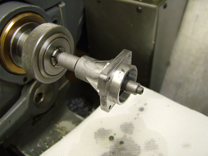
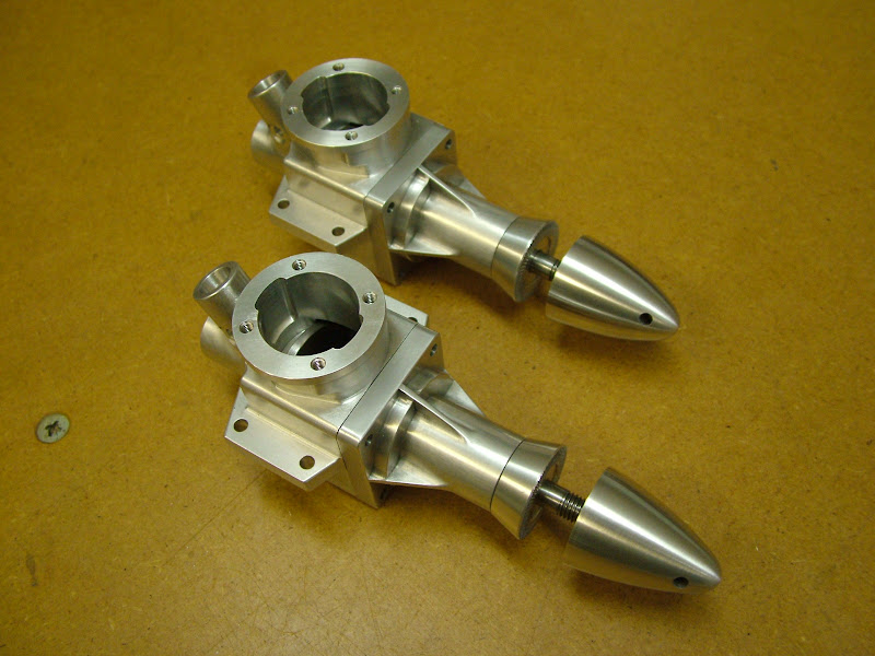
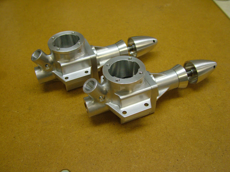
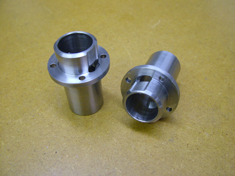
With the shafts lapped and fitted to their bores the prop driver and collet were tackled next.
Prop drivers can be awkward little parts to make particularly if they have a tapered recess to fit a coned shaft or a collet which then requires the OD to be concentric and front knurled face to be axially aligned. If it's not then even a small discrepancy will be magnified at the prop tips. The big problem is that of getting the tapers of driver and collet exactly matched and the best way of achieving this to my mind is not to alter the topslide once set

I admit to rather 'fussing' around this problem in the past trying to do it all in one hanging and turning the internal taper in reverse through the front face - fiddly indeed - but the following method was adopted on the ETA's where despite reservations it worked extremely well and certainly did so today.

First up was to prepare a blank .5mm over size and which was faced and had the taper cut.
DSCF0428.JPG


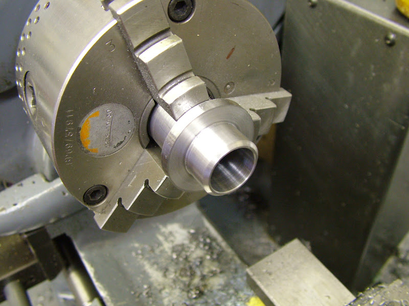
Parted off, it's reversed in the soft jaws and brought to thickness, parallel and the front recess turned. That finished the preparation.
DSCF0432.JPG


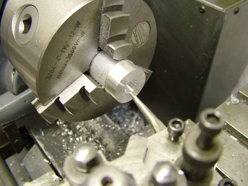
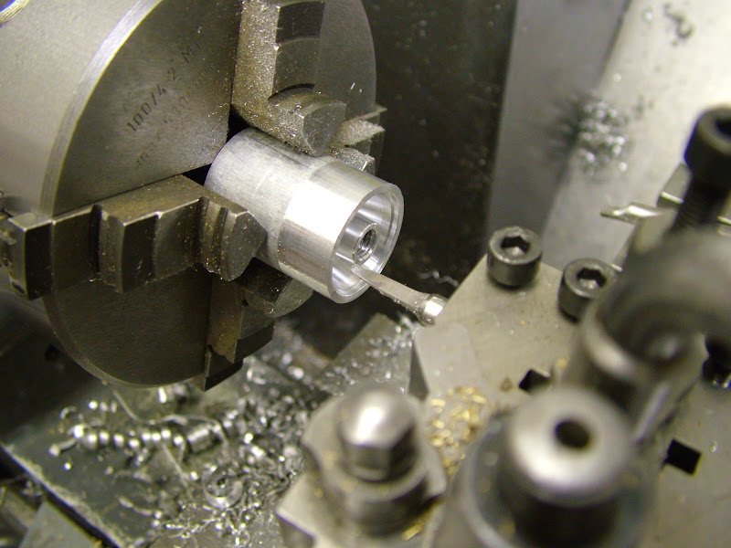
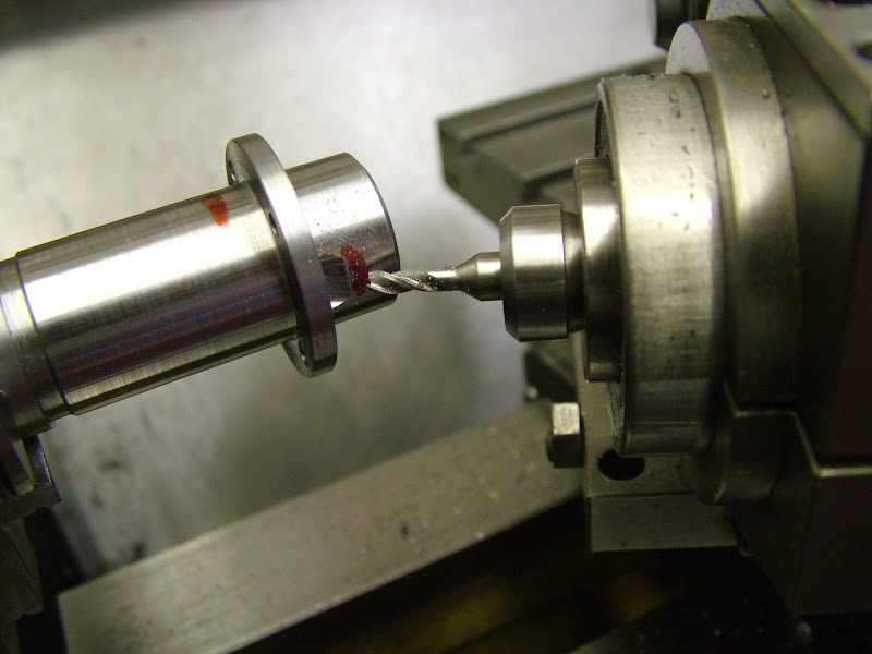
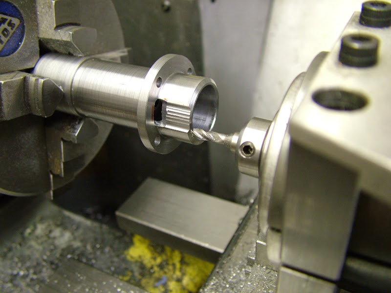
Next up was the collet (it is more practical to do this part first) - made from brass - ali could, and in all probablility would, pick up or gall on the driver making it extremely difficult to remove. The taper was turned using a boring bar with the lathe running in reverse.
DSCF0436.JPG


The blank was pushed on the taper and a parting tool brought up to touch the rear face.
DSCF0439.JPG


With the blank removed the parting tool was brought forward (away from the chuck) .5mm and then plunged in to create a lip (which on assembly will be just inside the taper). The tool was moved back toward the chuck .05 to .1mm beyond it's start point and the collet parted off. This will give the collet once pushed back against the face on the crankshaft a small ridge to apply a lever under for removal and also a .05 to .1mm clearance of the driver to the front housing. - Hope that all makes sense ???
DSCF0442.JPG


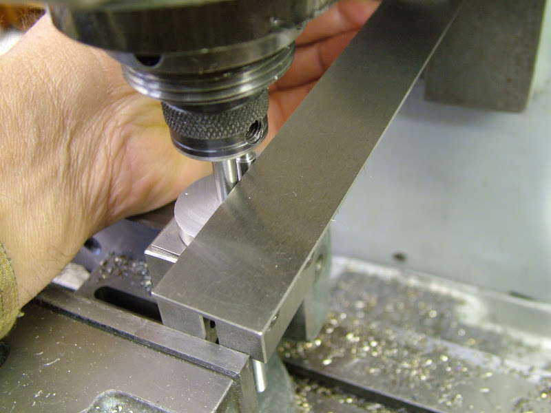
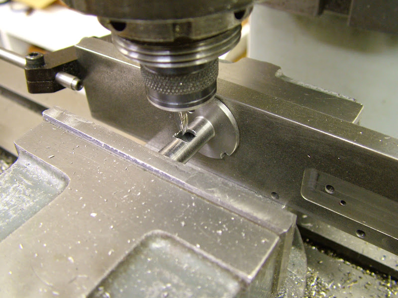
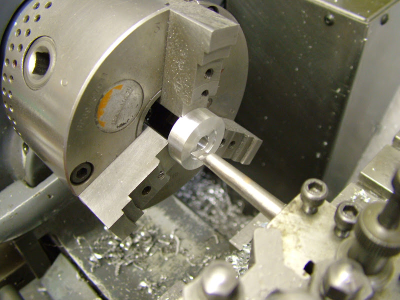
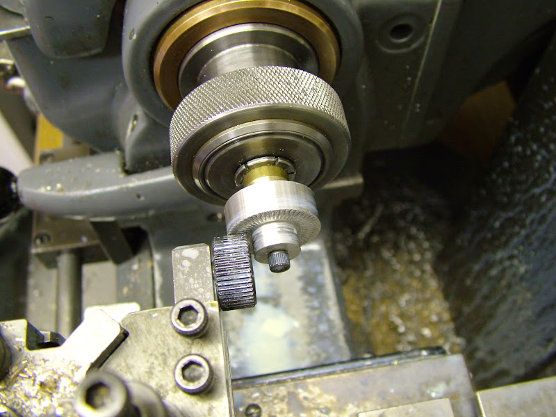
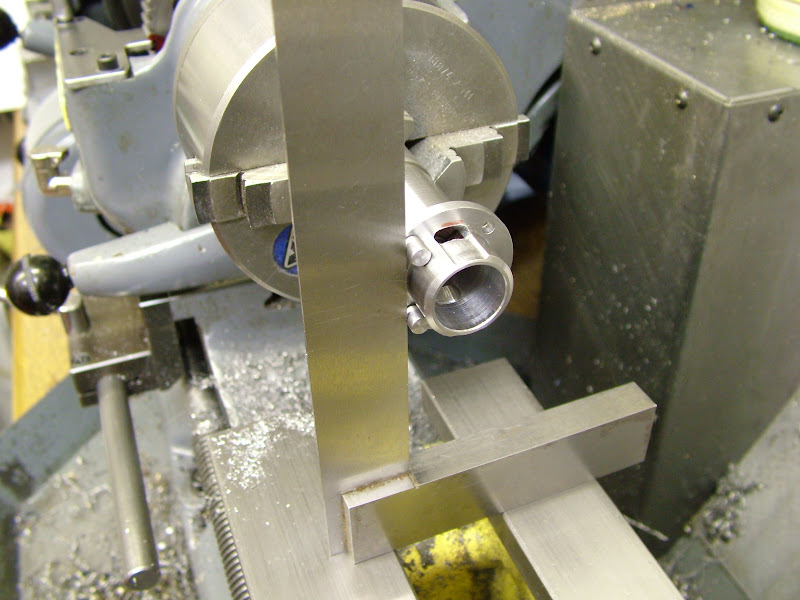
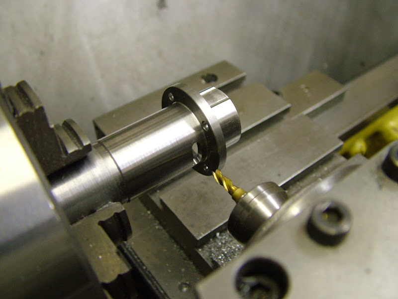
With the collet parted off another taper was turned but this time drilled and tapped 4BA. The prop driver blank was then held on this mandrel for knurling the front of the driver. The knurl is rotating on a dowel and is not captive being restrained in place by the thick washer. The cutting pressure was applied by the topslide leadscrew.
DSCF0447.JPG


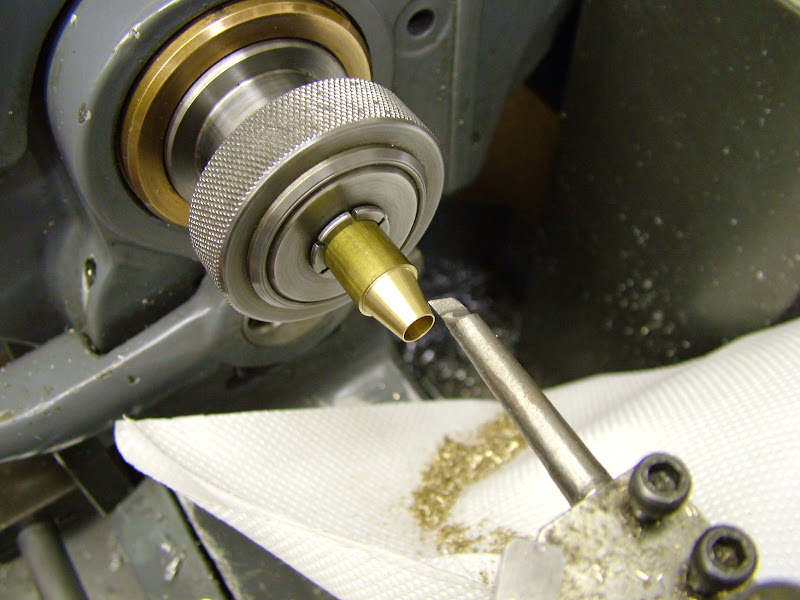
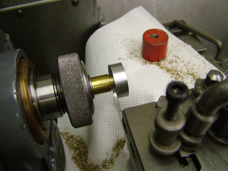
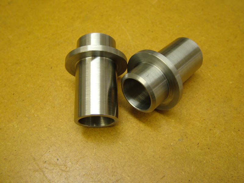
Once this was done the outer diameter and reverse taper was turned and the rough edges of the knurling chamfered. The thick washer was removed, the driver sufficiently tight upon the taper to allow chamfering the inner edge.

I managed to get a start on the spinners tonight too so if theres an opportunity to finish them tomorrow there'll be bit more later - failing that its next week as I'm off for a day out at Duxford Imperial War Museum on Sunday ;D.

Hope I've described these basic ops ok for those who haven't done it before - if in any doubt 'don't hesitate'....

Regards for now - Ramon


I love the index ring behind the chuck Ramon!.....bet you use it too!

Dave
 
Thanks Ramon for your detailed schooling. I love to read your threads they are just full of information, as I learn every time I read them. I look forward to your continued teaching.

Don
 
I like the lap design and have done a drawing in my note book for the next engine.

Jan
 
You are making good progress Ramon, you may have seen on ME that I have started their little Firefly .46 so may give your lap a try on that.

Is your pension not stretching as far as you hoped, I see you have started separating & collecting brass swarf ;)

J
 
Hi again guys, it's good to hear from you - thought you might like to know that it's arrived at 'halfway house' ;D

Managed to find some time this afternoon and evening to finish off the spinners........

..but first a pic of that collet just in case the description was a bit confusing. Sometimes, though not actually in this case, the collet tends to close a little when split. If no step is on the back of the collet it can be a real devil to get the collet moving enough to get something behind it sufficient to pull it off the shaft. Putting a step in it deals with that problem at a stroke.
DSCF0477.JPG


The spinners began by facing two blanks to length, drilling and tapping and then 'carving' the recess to remove at least some weight. However, these are very much 'cosmetic' to replicate the original spinner nut which was solid but as these will never be fitted to an airframe weight reduction isn't that critical. The tool was ground to approximate shape from the remains of a broken 1/4" long series slot drill and the 'carving was done very much 'by eye'. Both blanks had short and identical registers bored as an aligning aid in finishing the outside.
DSCF0449.JPG


The OD was skimmed for setting up in the mill to drill the cross hole on the centre line.
DSCF0452.JPG


A short stub of the same material was drilled and tapped for a piece of studding and a spigot turned to match the spinner registers.
DSCF0458.JPG


The blanks were then roughed as a series of tapers changing the spinner for each taper.
DSCF0460.JPG


Then each spinner was finished turned in one hanging again in a series of tapers before taking out the high points with a hand held scraper and the usual smoothing with a fine file, 240 grit emery, wet and dry and garryflex.
DSCF0464.JPG


So with all these bits made it was time for a halfway 'dress rehearsal'
DSCF0468.JPG


DSCF0473.JPG


The shafts turn freely enough and align with the valves okay however the bearings need fitting to be really sure that everything is in line but that will have to wait until the cases have been bead blasted.

Next up is the liners and pistons if the piece of material I have found is EN1a freecutting. If not some scrounging is in order ;) but what ever the tedious part is over.

Jason, Just trying (usually unsuccessfully) to keep it off the lathe bed, I tried collecting it but just found I had a swarf build up ;D Yes, I saw you're into the Firefly - watching with interest ;).
,
Jan, Re the lap - I found this to work very well and can see this method being pursued already visualising an 'improvement' by introducing a backing off screw mech. The only drawback I can see is that the force required to expand the lap is greater than the design I usually use however it can, unlike those, be expanded totally within the bore. More on this a bit later.

Dave - well spotted - they were put in that chuck around 1981 and I don't even 'see them' let alone think about them these days. You are right they are very useful and thought perhaps that it should have sufficient interest to warrant another post on it. Taken some pics tonight but it's an early rise in the morning so will not be able to do that until tomorrow night or Monday.

A day off from engineering then tomorrow to bask in the delights of the plastic model.

Regards for now - Ramon


Nice going on the spinners - I presume that you worked out all the tapers beforehand to get the (presume parabloid) shape ?

I have turned curves by that method - but I used a wood chisel (horrors) on a rest to finalise the shape - it works well and the Aluminium comes off as very fine fluff. (Using the chisel upside down like a zero rake tool)
A word of caution on that method - ensure your tool cutting edge is on centre or below - above centre leads to a loud bang as the tool digs in - damaged part, chipped chisel, soiled underwear etc. etc.

That's what happened to me the first time I tried it - but lesson learned, it hasn't happened since.

Ken
 
Very nice work and informative as usual Ramon.

Vince
 
Smashing!.......I think that means Wicked good!
;D
Dave
 
Oh WOW
They just look fast !!
I love it.
Pete
 
Hi guys, well it was a great day out yesterday but one which left me feeling quite tired by it's end. Pleased to say one of my models one it's class but then there were only two entries so no big deal but nice never the less. Obviously felt too tired for this last night :eek:

I'm afraid there was very little scientific reasoning behind the spinner shape - very much an 'if it looks right it probably is' approach. Though drawn on cad it was just an arc drawn between the nose radius and the back face and stretched until it looked right then mirrored. A number of lines were drawn and the angles measured as here ......
spinner%2520clip.jpg


I used the same method as you describe Ken, scraping around the profile removing the high spots until it looks reasonable. The tool I use is made from an old file (about 16mm wide , 3 thick and and about 200mm long. All the teeth are ground off and the end has a slight radius across its width the face being 'hollow ground' by holding square to the offhand grinder. The 'rest' is just a piece of 3/8" x 1/4" gauge plate held in a toolholder, positioned as close to the work as possible and set such that the top of the scraper is just on or just below centre line. Being flat - unlike the front of your upside down chisel :eek: ;D - its much easier to control and rarely digs in.

Having ascertained that that piece of steel was indeed freecutting ;D work began on the liners today. Although a basic, straight forward, turning job a little care in the process will ensure good results .........

The blanks, faced square and to OA length plus .5mm had the top end roughed out leaving it 3mm up on finished diameter.
DSCF0505.JPG


They were then held in the three jaw and drilled (3 steps - 4, 12, 16mm) first before being returned to be bored to within .5mm of finished diameter. The boring bar used was as big as could be got in the hole and the tool bit was ground by eye to give near enough a 45 degree lead
DSCF0518.JPG


The od was turned leaving .5mm on diameter too. The chuck was then released and gently retightened with just sufficient force to grip the part for finishing the bore to size as well as the od and lower face of the flange. By leaving 3mm on the top portion the increased wall thickness left after boring and the very light clamping pressure minimises any likelyhood of the bore distorting when turning - something that will manifest itself immediately when lapping - a 'much better to eliminate it before it happens' kind of thing
DSCF0515.JPG


DSCF0508.JPG


With the bottom ends done they were then held on an expanding mandrel for the upper OD and OA length to be finished and the flange brought to final thickness.
DSCF0521.JPG


Next up will be to get the exhaust ports milled in then tackling those transfer ports.

As always, thanks for your comments and input Thm:

Regards for now - Ramon


PS - Dave (Steamer) just posted some pics on the Machine Mods page of the chuck dividing device


Hi again, heres a little more detail and a few more pics of finishing off these liners.

It was intended to do some of these milling ops on the mill but in the end the entire job was done on the lathe using the cross slide drilling/milling attachment.

Held on another 'recycled' expanding mandrel first up was to drill the four holes for the hold down bolts.
Leaving the mandrel in situ the chuck was removed and, using a collet chuck, two small pegs were then turned that fitted in these holes with a nice slide fit. The heads of these pegs had identical diameters and would be used for setting up the liners between ops.

After the drilling was completed the chuck holding the mandrel was refitted ready for the milling. The milling attachment was set at 30 degrees and the transfer passages cut first using a 3mm FC3 cutter to plunge through then widening the slot by indexing the chuck one tooth at a time - three teeth each way - plunging through each time to create the slot. To mill the ridges that were left lowest back gear was then selected and the chuck rotated by turning the main pulley wheel by hand. There is a surprising amount of control doing this and little fear of the cutter overiding the gearing and pulling itself into the work.

DSCF0531.JPG


Both passages on each liner were done before the next op which meant re-aligning the liner to the bull wheel for indexing each time and this is where those pegs came in
DSCF0538.JPG


After milling the passages and deburring the liners were set in the cases. The passage up from the case looked a bit restricted so it was decided to open this up a little - plunging and rotary milling by the same method
DSCF0533.JPG


Finally with the attachment reset the exhaust holes were milled, again by adopting plunge cutting and rotary milling using backgear and the main pulley.
DSCF0541.JPG


The finished liners are now ready for lapping ......
DSCF0548.JPG


......... before tackling the pistons and contra pistons but these will get left until last of all - I always like to have a really good clean of the lathe after using cast iron so that may as well be at the end.

It's back on the ali then - cylinder heads and conrods - but first I have some prepping to do - I'm off to see my friend Lee on Thursday and an opportunity to use his bead blaster ;D.

Regards for now - Ramon


I've been following along quitely. It looks excellent!

Is there a photo of that milling spindle for the lathe? That looks like a nice piece.

I'm cleaning up my shop to rearrange everything, so I don't have anything to talk about lately.

Greg
 
Oh Ramon!
First flattery. And now you tease us with that spindle!?

Bad boy!
;D

PICTURES PLEASE!


Dave
 
Impressive!

I just don't know what else to say!

Dave
 
Ramon I just can nor get enough of your threads. I enjoy it very much. You never stop amazing me on how much there is to learn in the craft and all of the steps you take to complete it. Thank you very much for your continued progress. :bow: :bow:

Don
 

Latest posts

Back
Top