Super Tigre G32 1cc diesel - a 5cc version

Home Model Engine Machinist Forum

Help Support Home Model Engine Machinist Forum:

This site may earn a commission from merchant affiliate links, including eBay, Amazon, and others.
Would that "something else" be a build article on the ETA to go into ME?

Keep the posts comming they are handy for my Firefly build ;)

J
 
That photo is staged, just like the moon landing. How come the white background isn't all stained with semi-toasted castor oil?
 
Well I don't think I've had the pleasure of being accused of falsifying something before :eek: :eek:

Sorry to disappoint you RK but theres nothing staged at all. Its just outside the workshop, piece of floor covering over a very tatty old table and a pristine piece of white faced hardboard set behind. I usually use an equally tatty piece of 1/8 ply which is totally oil stained as well as pockmarked with welding burns - not ideal for a backdrop for a decent photo as I'm sure you'd agree :D. Can't comment on the moon landing though.

Might be Jason but then again... ;) - the Firefly is looking good BTW

Dave - you must have missed this http://www.homemodelenginemachinist.com/index.php?topic=16281.msg165815#msg165815

I was hoping to put a bit up tonight but things have conspired today and it's Para night tonight so back tomorrow

Pete, thanks for the PM - will respond later.

Regards for now Ramon

 
Hi Guys, Despite a lengthy interlude today when my friend Lee came over I managed to finish the needle valve assemblies and get a start on the pistons.

Courtesy of Lee I now have a lovely set of filing drawers to fit into the wall unit in which to centralise all bits 'engine' - previously most are frequently 'unfindable' having placed them 'somewhere safe' where they'll easily be found ::)) Does anyone else suffer from this infuriating malaise???

The NVA's are basic turnings in brass, usually made from hex bar though this time they were made from round and had the hex milled on to obtain a more consistent finish. One thing that may be of interest having seen in the past some pretty esoteric ways of achieving one is making the needle itself.

I prefer to use pianowire - depending on the type of valve either 18swg -.048" usually loctited into a piece of 8BA threaded rod which is clamped by a closing nut on a split taper or 16swg - .063" for the more traditonal type as on this engine.

Piano wire is pretty tough so the initial shaping is done on the side of a grinding wheel. To keep good control a piece about 150-200mm long is held at an acute angle and rotated between the fingers using both hands to try to ensure no dwell spots. (Theres only one in the pic - the other has the camera) Ink helps here to keep an eye on any eccentricity which, though not super critical, is more important to keep an eye on than the actual taper. Having buggered this one up one-handed it was ground off and started over ;)
DSCF0723.JPG


Any slight eccentricity can more or less be removed by filing using a wood support block. The block is set so that the needle is just below the top face. The lathe is run up and the block advanced to support the needle. It can now be smoothed, elongated and finished off using a needle file - preferably an old one as files don't take too kindly to piano wire. The wood wants to be fairly hard to support the needle against the filing pressure.
DSCF0718.JPG


Once happy that it is running as true as possible - if it's not it can make turning in the spray bar difficult - it needs to be set in the needle housing. One of the problems with using piano wire is that there is no drill size that's a good match which can make for a wobbly needle if drilled over size. A way around this is to grind a piece of the wire at an acute but flat angle and use it as a reamer, a task which it does very well providing the swarf is removed frequently - if it isn't it soon crowds and gets stuck - yes you guessed ::)
DSCF0712.JPG


DSCF0714.JPG


After reaming, the hole is deeply centred for a solder 'pocket' and its ready to fit
DSCF0728.JPG


The needle was pushed home and some fuel tubing connected so that it could be tested for sealing by blowing.
The housing was screwed all the way home and then backed off 1 -11/2 turns then the wire soldered letting the solder build in the pocket. By not fluxing the needle before but only after assembly minimises the likelyhood of the solder running through and soldering the housing to the spraybar - and yes you would be right about that too ;D
DSCF0730.JPG


After cutting to length the ends are radiused on the off-hand grinder before bending - it's much easier than after ;)
DSCF0734.JPG


And there they are done - a simple part but one that needs care in manufacture more than 'high tolerance' if it is to function efficiently.
DSCF0740.JPG


It's the last 'knockings' now, pistons are turned and milled up to finishing the OD but first comes the wrist pins - isn't that a much better phrase than 'gugeon pin' - and getting them fitted before lapping the liners and finally the pistons. Sues off to a girly thing so tomorrow could be a long day ;D

Regards - Ramon


Ramon said:
It's the last 'knockings' now, pistons are turned and milled up to finishing the OD but first comes the wrist pins - isn't that a much better phrase than 'gugeon pin' - and getting them fitted before lapping the liners and finally the pistons. Sues off to a girly thing so tomorrow could be a long day ;D

Regards - Ramon

So they'll be running by Sunday then? ;)

Here's hoping!
 
Hi Anthony, not quite, at least not till the anodising's done but should be early next week if the lapping goes to plan ;)

Regards - Ramon
 
This whole build has been impressive so I almost hate to comment on something so simple, but the wood block trick is one I will have to file away for later. (No pun intended)

Thanks for all the effort you put into sharing your builds!
 
Hi, Ramon still here enjoying your progress and still great quality as usual. I taught I was the only one who had a safe spot to put stuff and can't remember where the safe spot is when I want things.

Don
 
Hey Ramon,

NOW I remember....was having a senior moment there. NICE

And I have absolutely no doubt as to the validity of the photo!........

Can't wait for the little beasty's first fire.

Dave
 
Why the split nut for holding the needle? Is it so it can be squished a bit so it doesn't vibrate out?

Brock
 
Hi Brock, congrats on getting your engine running Thm:.

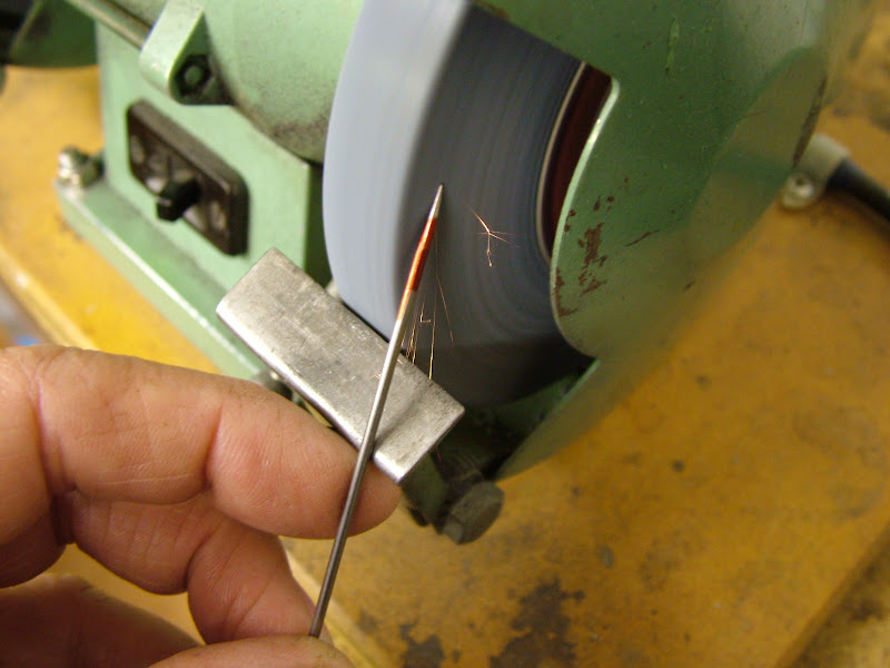
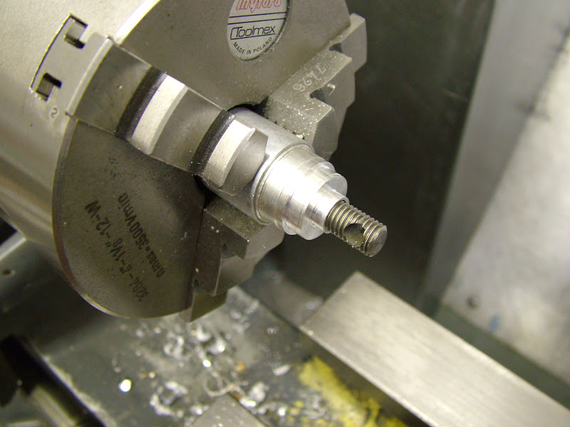
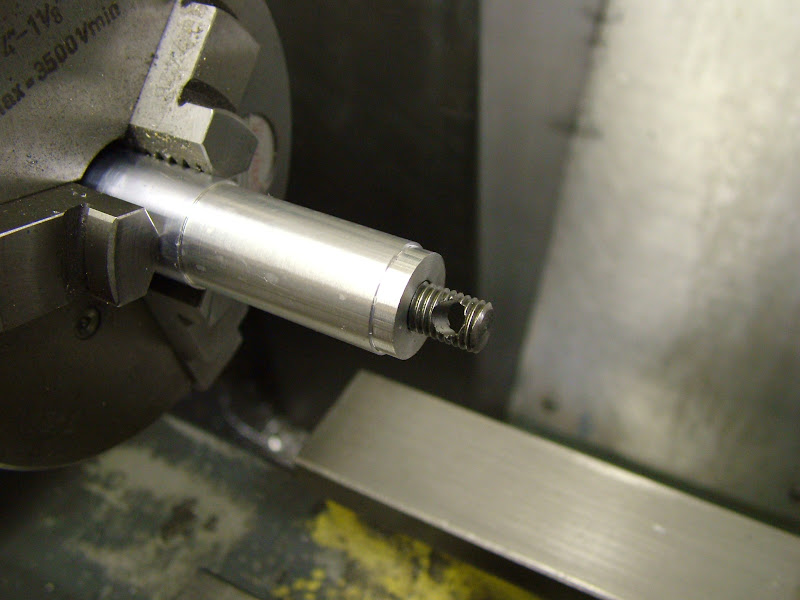
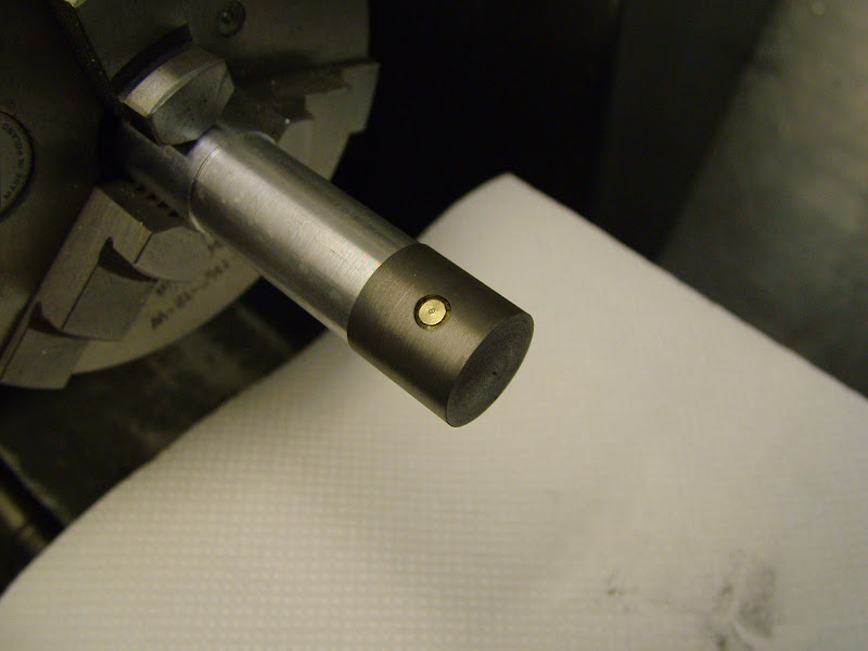
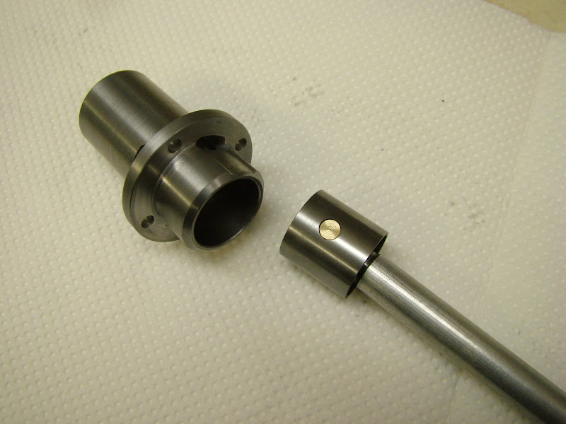
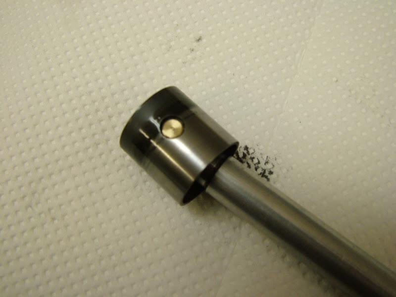
Re the needle yes that's what the split is for though its not a very efficient way of restricting a needle from turning as with time it wears and loosens. Seen some pretty manked up NV's over time where they've been squeezed with pliers to get that last little bit of nip. This is true to the original though so really needed to be used. When flying I much preferred to fit the threaded needle type like the later Super Tigre engines had - very fine control and adjustable friction using the clamp nut.

I just knew I wouldn't be alone in 'losing' things Don, I really am bad for it. Also suffer from 'Bench Blindness' - apt description that - someone aluded to it on the ME forum sometime back. I spend countless time looking for things that are right in front of me - the classic is the spanner for the lathe toolholders, that's always 'gone' :eek:

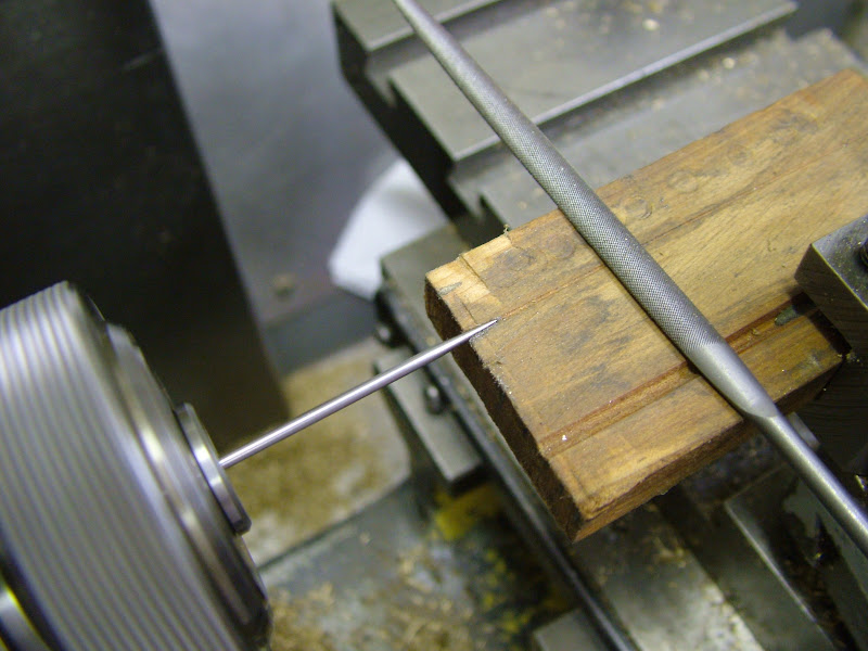
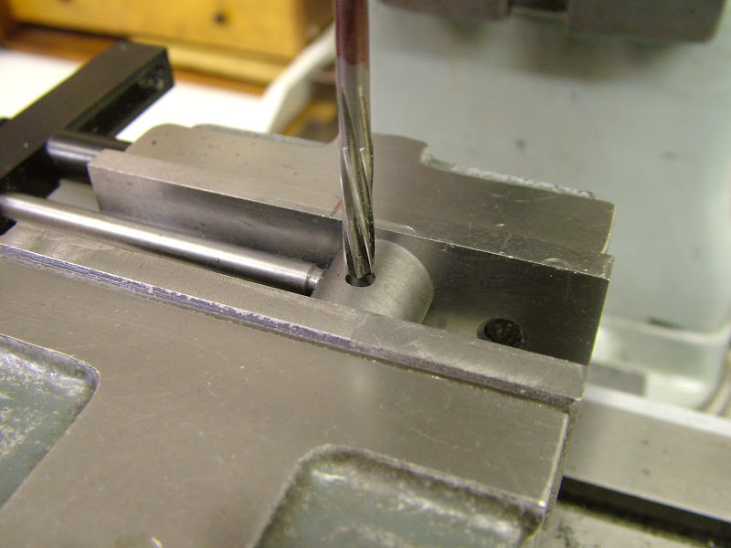
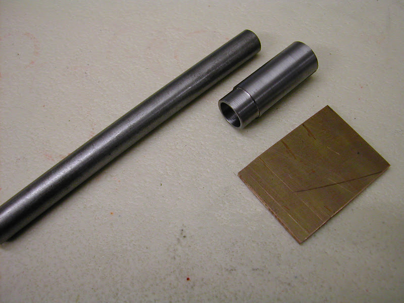
'rhi' - That small piece of wood has proved so useful, not just on needles. It's a great aid to filing tapers on flimsy rods too - note the long 45 groove.

Hopefully it won't be too long now Dave, today saw some further progress but not as much as I'd hoped......

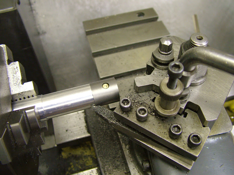
First off I turned the piston blanks and drilled and reamed them for the wrist pins. Did this in the mill to ensure squareness. The blanks were left .5mm up on diameter and 1mm longer on the top end. The inside diameter of the skirt was made identical for locating on a turning fixture similar to the spinner
DSCF0741.JPG


They were then held in the chuck on the rotary table to mill the insides. The wrist pins were turned from silver steel and honed to a tight push fit in the piston blanks and these were then set aside until the bores are lapped
https://lh4.googleusercontent.com/-teq1eaoN2dU/T-9isDTEzLI/AAAAAAAAGjM/RPe3GpNkf4c
/s800/DSCF0746.JPG

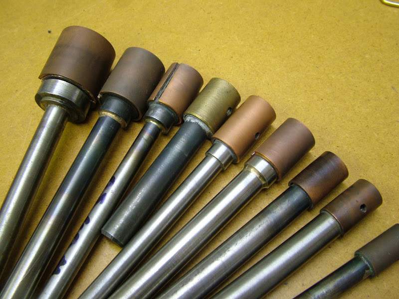
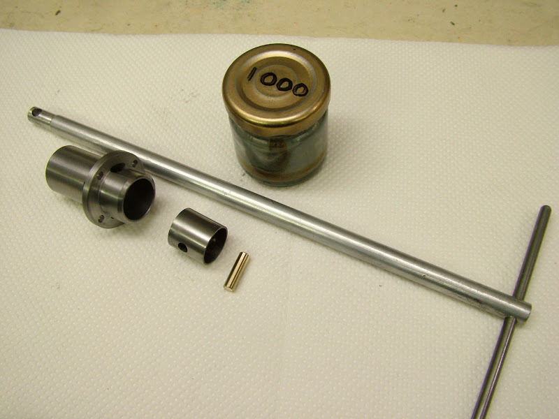
I mentioned before that I had always used one type, that is, style of lap other than that single ali one and these are some made over the years..
DSCF0792.JPG

The first was the second from the right done for the bores in a Quorn. I'm not sure where the design came from but I think it was Len Mason. At the working end they consist of a 'D bit' like section to which is silver soldered a ring of (preferably) copper. The ring is expanded by inserting the remaining piece from when the 'd' section is cut(by hacksaw) and a screw that bears on this from the fixed side. They are not that complicated to make but do take longer than most and certainly longer than the ali type used on the crank cases. They are however very easy to adjust and work extremely well.
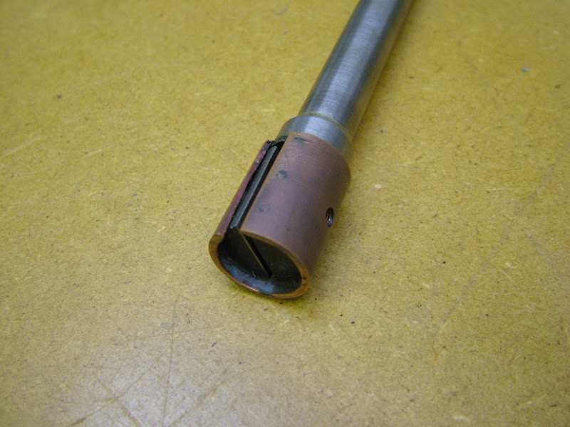
This should give a better idea of the make up
DSCF0750.JPG


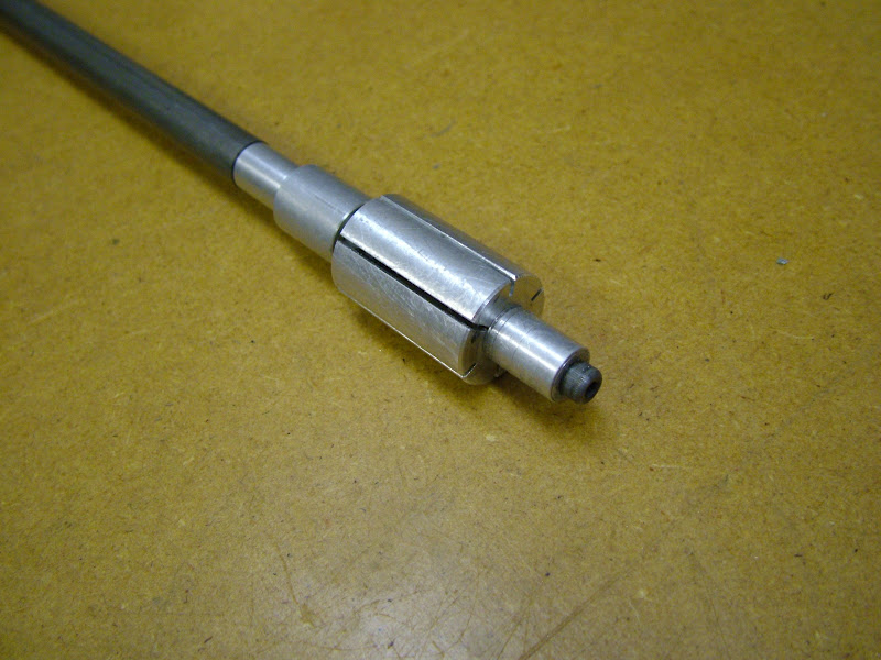
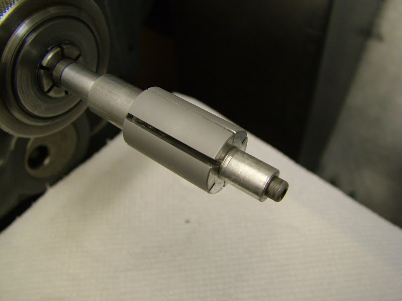
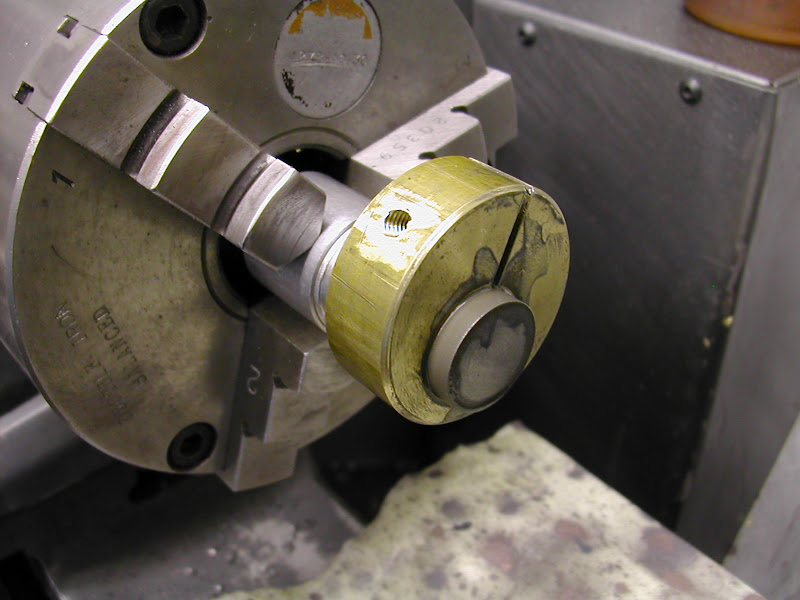
Far quicker to make was another ali one - this one is 18.3mm dia..
DSCF0753.JPG

.. but despite what was thought were fairly deep grooves to lessen the expansion forces it proved very difficult to expand with a 4BA caphead and allen key. It did work well as a lap though so deeper, perhaps wider grooves are required to make things a lot easier. Personally - I think it's worth the effort to make the other type - far more control during lapping but that said this type does have merits so perhaps a bit more perseverence first.

Re lapping, this is not to teach granny etc but for the beginner this can be a frought moment. It's not a difficult process however and providing the finish is good to begin with is a reasonably quick one to carry out. For those with an interest then this is how I went about it.

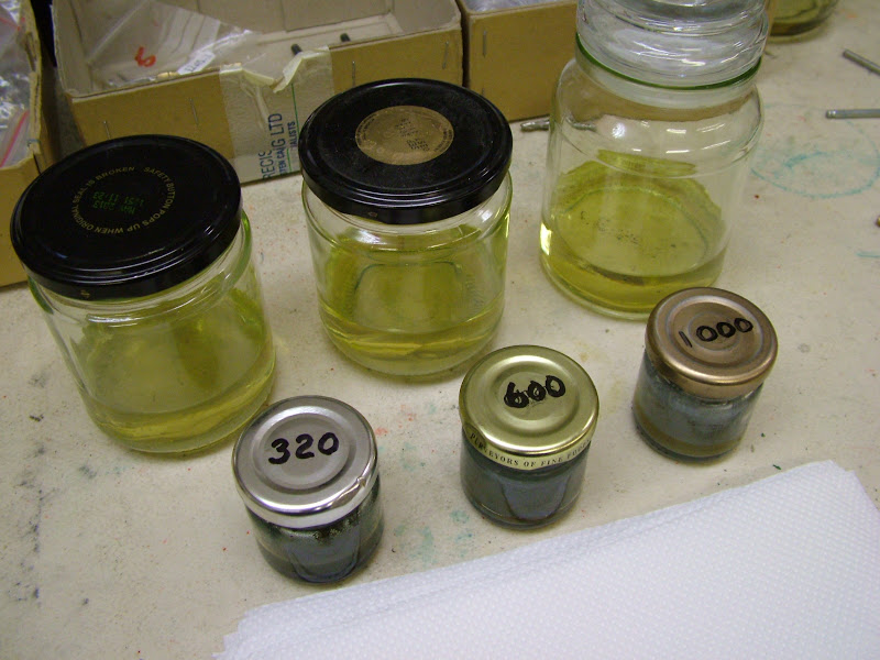
As these liners are unhardened metal the compound used was silicon carbide mixed with thin oil. Diamond paste, although available, is not because of it's tendency to embed itself into soft metal. Difficult to remove unless cleaned in an ultra sonic cleaner the risk that the piston or liner could actually end up acting as a high speed lap on initial runs is not worth taking - Silicon works fast, cuts quickly and is easily cleaned. Originally I used petrol but by using three jars containing a small amount of cellulose gun cleaner the part is squeaky clean after a visit to each jar. When the first jar gets too contaminated it's decanted into another for settling and recycling , the jar cleaned and topped up to now become the 'third' jar. Smelly but efficient ;)
DSCF0766.JPG


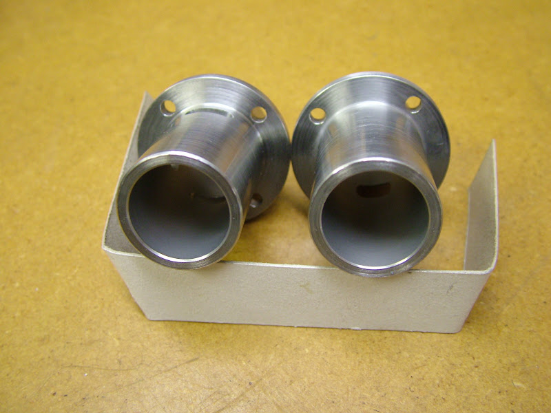
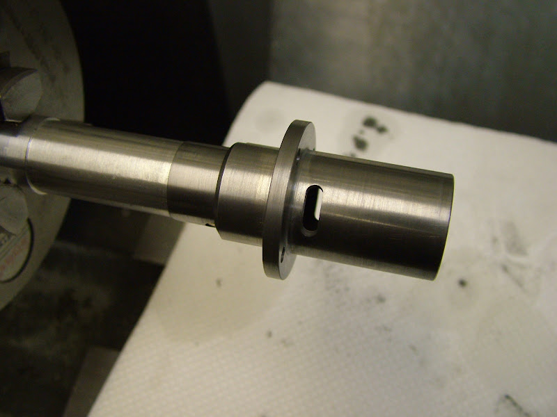
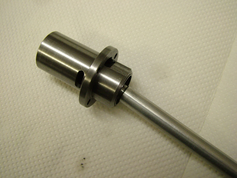
To save going back in the thread the liners before lapping looked like this..
DSCF0761.JPG


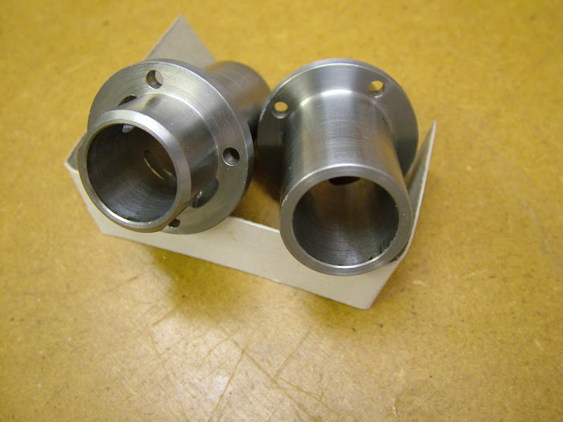
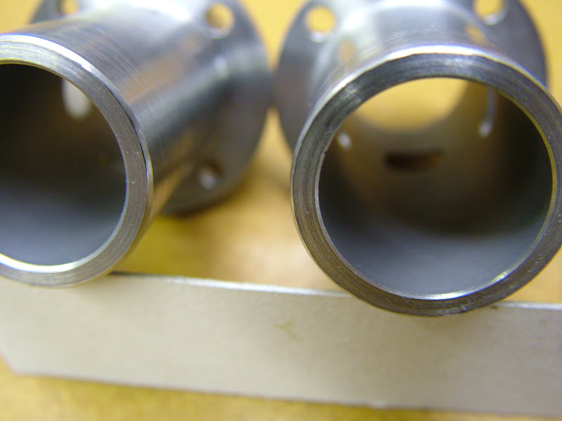
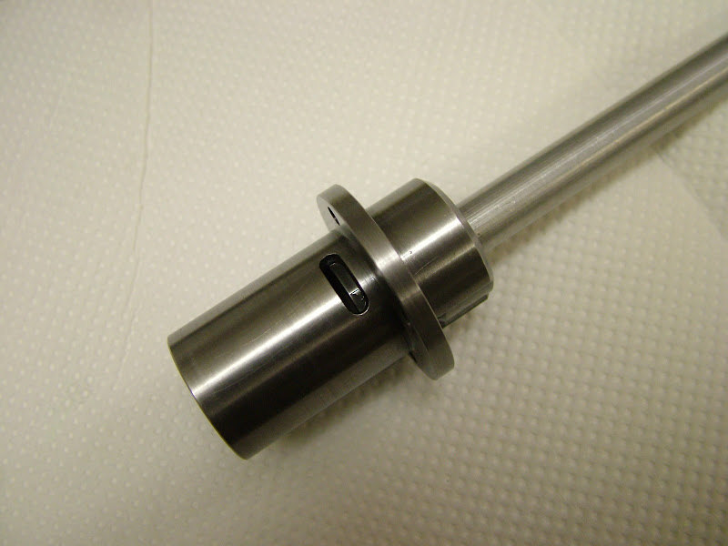
The lap is lightly smeared with compound and the liner slid on and worked about to spread it around. Lubricated with paraffin and oil the lathe was run about 300 rpm and and after about ten minutes with 320 grit they looked like this..
DSCF0768.JPG

The one on the right still exhibits the traces of turning so was put back up for another session before cleaning thoroughly - including the lap - before recharging with 600 grit
DSCF0772.JPG


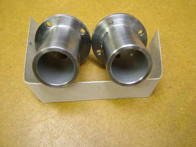
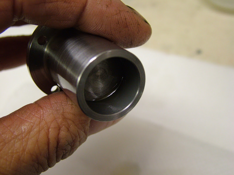
Another 5mins or so with the 600 produced an overall even, silky smooth finish suitable for accepting the piston once finished (the piston will be lapped to the bore)
DSCF0779.JPG

DSCF0783.JPG


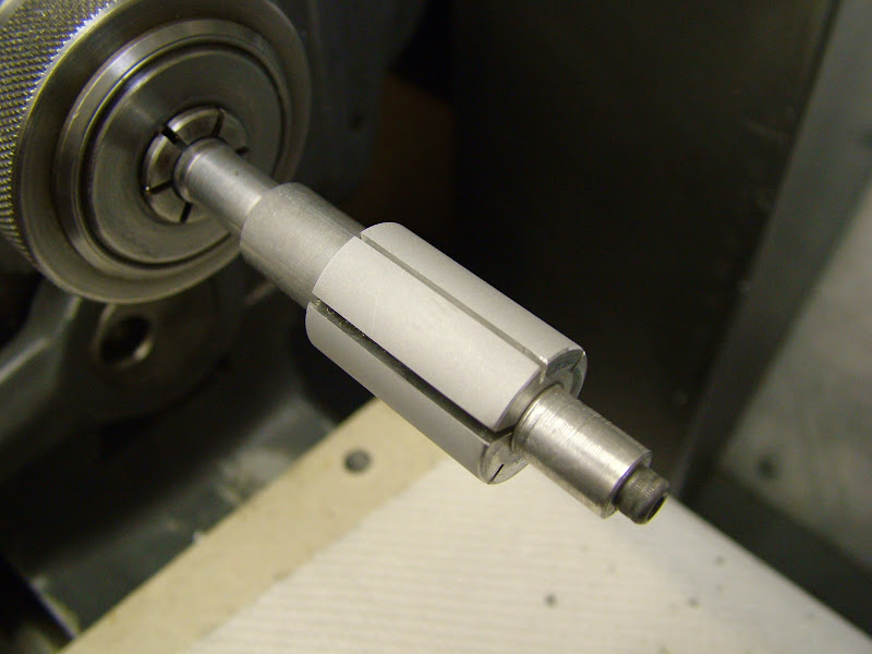
A bit more about the lap - at this stage it could not be pushed up the taper by the 4BA screw, the 'tee handled' allen wrench twisting alarmingly. Changing to an ordinary long series key fared no better.
DSCF0788.JPG

The split has opened considerably showing a degree of expansion but not the amount available with the other type. No doubt about it though they are quick to make, but need a thin wall to make expansion much easier - a re-think required then scratch.gif

Sue has ideas about the garden tomorrow :eek: :eek: :eek: ::) but then again it might rain ;D - whatever, I'll get on to the pistons as soon as some devious contriving will allow ;)

Regards for now - Ramon
 
Ramon -

Can I ask for a bit more information about your D bit style lap? I'm not getting a clear picture of how it works. As I understand it, you start by cutting a D bit shape, so about half of the diameter of the main lap shaft is cut away. So far so good, but then I think you say that you solder the copper ring to the end of the shaft. This means (I think) that only half the ring is actually attached by solder, the rest is unsupported at this stage. Then you re-introduce the part cut out and force this out with a screw in the solid side to give you adjustment. Doesn't this result in a rather distorted, non circular lap? I appreciate that it will become circular again with use, so perhaps this doesn't matter but I'm not sure I am understanding the principles correctly.
 
Hi Bill - sure thing. I see I missed a bit out ::) and haven't made the soldering part clear either. I also forgot to mention it is turned before use ::) ::).

You have the basics but I just remembered doing some pics for a similar question on the ME forum when describing the Etas - perhaps they're worth repeating here as they show it in much better detail.

These are the only parts save the screw - if the lap is bigger than 1/2" diameter so far they have had the 'head' silver soldered to a 1/2" max dia shaft. The copper, cut from 10swg sheet is rolled (actually beaten around a suitable size form) to form a tube such that it it leaves sufficient material that it can be turned to size after soldering.
DSCN3097.JPG


DSCN3101.JPG


It's then carefully, and with minimal solder, soldered along its leading edge ( It will quickly unwrap on turning if it's the otherway round)
DSCN3105.JPG


The insert is inserted and the screw tightened to just hold it in place then the OD is turned to about .025mm below the bore. Very sharp tool required and light cuts.
DSCN3109.JPG


And its ready to use...
DSCN3112.JPG

This lap did these three liners for the Eta's. Within the usual basic measuring kit I have no discernable out of roundness has ever been found despite the fact that the lap does not open completely evenly. This lap here certainly did more work than any of the others apart from the one used for the Bentley liners. By the time it had done all three the copper was slightly worn toward one side but still perfectly circular - to micrometer readings.
Unlike the ali lap it cannot be expanded when full in the bore unless there is an opening eg and exhaust port but I have never found this to present a problem, just bring the lap out sufficient to expose the screw, tighten slightly, then carry on

As mentioned before I'm not actually sure whose design it was but it was someone well known for their engine building. I made the first one to size the bores in the feet of a Quorn T&C and it worked so well I've stuck with it until now.

Hope the above clarifies it a little better if not just come back

Regards - Ramon


Well, I've just been 'converted' from using hardwood dowels for laps. Your approach seems a slight bit of work but I really do like the final results. Well done and thank-you for showing this method and procedure.


BC1
Jim
 
You have convinced me it looks so easy to make. Thanks Ramon for the detailed explanation. From what I have seen of the final bore of your cylinders it work very well.

Don
 
Thanks Ramon, I understand it now, and can see how it would be useful. I will be making some of these.
 
Hi Guys - glad to see that that was of use to you ;) I would just add that by being able to turn either type to the size required and with a good finish gives a good start to the process.

Well the pistons have now been machined and successfully lapped to the liners. Always a tense period as there is so little material between a good fit and a start over fit. These ones have come out well I'm pleased to tell.

I took lots of pics of this op which I hope will help explain it better than describe - the technique is not mine but once again that of my all time engine hero 'George Aldrich'. As usual, this is not for teaching Granny but for those who may feel a little trepidation in tackling it.
If it's borne in mind that it's an operation that cannot be rushed, a slow, gently as it goes, approach will bring best results. It's not difficult just time consuming. It is easy however to go beyond the 'break point' if you go at it too enthusiastically.

Lets step back a bit first. When lapping the liner, once the surface is uniform and even all through, the lap should be allowed to dwell at a point below the exhaust line. This area has no effect on compression and can be a couple of tenths larger to an advantage for lapping the piston to the bore. This is not measured - just done by feel. While on this matter it is often recommended that a taper be induced in the bore - indeed something GA was an advocate of and something that will improve performance in a high performing engine but for an engine such as this no attempt was made as it's really not worth the extra time.

So with the liners finished and cleaned it was time to finish the pistons. The piston blanks need turning on the OD's and facing to length so a fixture is required. This one has seen several pistons, each time turning the shoulder back for the piston skirt to register on.
DSCF0795.JPG


Unfortunately it was not long enough to accomodate the hone movement so a new one was made. It is back drilled clear on the screw so that should the piston prove difficult to release then the rod can be screwed out from the back end.
DSCF0798.JPG


An undersize (4.7mm in a 5mm hole) brass pin is inserted through the piston and the screwed rod then the piston screwed up tight. By using an undersize pin no influence is placed on the piston save via the register. Once on the piston OD and the slightly coned top face was turned
DSCF0799.JPG


Setting the Myford top slide over at such acute angles means the normal handle fouls the cross slide bracket. Using a 2BA screw and ball driver gets over this at a stroke
DSCF0803.JPG


The piston after turning and honing. Doesn't look that good in this pic but it was very smooth.
DSCF0806.JPG


It should be honed (or lapped) so that - after cleaning - it will just fit into the bore about a third
DSCF0807.JPG


If no hone is available then an easily made piston lap will do- this was the one used on the Eta engines
DSCN3127.JPG


Both piston and liner are scrupuously cleaned before the next stage. A tee handled driver is required and another brass pin, this time one that fits the piston and a very small amount of 1000 lapping compound.
DSCF0810.JPG


The piston is attached to the handle and it's ready to go - a very small dab of compound is smeared just inside the bore and a very thin smear over the piston then some thin oil applied. The amount of compound is very tiny too much and the piston will jam.
DSCF0813.JPG


Holding the liner tightly the piston is inserted slowly then with a wringing rotary back and forth twisting motion the piston is slowly lapped to the lower bore. It soon begins to dry - a good indicator is it squeaking - this is a little out of focus but you can see the dry band at the top of the piston. No further compound is applied at this point- just plenty of oil and continue the wringing action.
DSCF0820.JPG


Once the piston is in just over half it's length remove, clean thoroughly and oil up then try. It's surprising how much 'space' the compound has taken up and this will give an indication of how to proceed. This is done a couple of more times - slowly is the key....
DSCF0824.JPG


DSCF0826.JPG


DSCF0829.JPG


Until the piston is in the bore it's full length or up to the exhaust port
DSCF0834.JPG


Remove it and wipe both parts clean (this will leave traces of compound)- the bottom of the bore should look shiny
DSCF0837.JPG


Oil both parts liberally - there should be no need for further compound - and slowly repeat the procedure until the piston will suddenly ease through the bore with a degree of restriction. It only needs go as far as where the contra piston will sit. Once this happens the piston is removed and and both parts thoroughly cleaned of all traces of compound. Then oiled and re assembled - just working with oil at this stage is sufficient to 'work' any tiny restriction that may be felt
DSCF0839.JPG


Well that's it for tonight - that's a long post so I hope it's not too long winded. Two last parts to make tomorrow - I had forgotten about the contra pistons ::) then it's the anodising. Oooh it's getting close :)


Regards for now - Ramon


Excellent write up Ramon! :bow:

Nice treatise on lapping!

Dave

 
Very very interesting Ramon.

lapping is something I've always tried to avoid hence i only build steam engines, this has given me a master class on how to.

Stew
 
Morning Guys

I should point out Stew that this is not the kind of fit I'd be looking for on a steam engine - that would have to be much better :big: :big:

Model diesels by their very nature rely on good compression to perform well not to mention start well. Given the basic kit at my disposal so far this technique has worked well either on those built from scratch or refurbing/rebuilding worn engines to achieve a good piston/liner fit. So far I've used it with good results down to 1.5cc but yesterday as I was 'twisting away' I couldn't help but think how difficult it must be in those smaller size engines like the Nano's RK built. No doubt about it, '5cc' is a nice size - for me ;)


Regards - Ramon
 

Latest posts

Back
Top