Some of my stuff...

Home Model Engine Machinist Forum

Help Support Home Model Engine Machinist Forum:

This site may earn a commission from merchant affiliate links, including eBay, Amazon, and others.
Yep, you've echoed what I said about Mamods on another forum, but like you've related John, low pressure. I wouldn't trust it on a firetube type boiler though, personal preference. Regards Ian.
 
And now another engine; scratchbuilt trough and through:

347_17106db007efd779e8a0006e8126c94c.jpg


347_7b80a6c9010d2ca5ca9b8463450ad955.jpg


347_8d0d38f34bdbd117fe51da7ae734a1a7.jpg


347_80f2e08bf81acabf19f829689da15aee.jpg


Specifications:

Bore: 14 mm
Stroke: 28 mm
Pistonrod dia. : 3 mm
Valve rod dia. : 3 mm
valve stroke: 2 mm (its being reduced by the lever in the middle, i first designed another valve but it didn't work. Then i redesigned and now it works very good.

The flywheel has 10 cm diameter and the crank is ball beared.
Later on, i added a cross clamp guidance (is that the correct expression?)

In the future, the engine will get a new base but ill wait until i have the boiler and i build it all on a tray.


Florian
 
Nice looking engine. Looks like you got about a $100 worth of brass there at today's prices! ::)

Chuck
 
Hi there Florian
may i say what excellent work you have produced.
keep it up !
Kind regards
Malcolm
 
I think you all kind of expected to see some more things from me, you were right! :D


66_7a3cabf9f94089c9d0f5b83ac07cc97c.jpg


66_5ce2ce37f10d66b98fac429bf8214ae0.jpg


66_f5816d5794495603e8143221e18e65f7.jpg


66_e237c891e1ac3a2129128c66a88fa2b1.jpg


66_9d880991bcc7c7522480eabc6ce09a7c.jpg


Its a little steam engine with a stephenson reverse gear.
And now: All the cylinderhead-screws are M2 screws; their head has 4 mm diameter.
The Flywheel has 40 mm diameter.
Bore: 8mm
Stroke: 9.5 mm
Valve-stroke: 2mm

It looks very good like that, but it does not work that great and so i decided to modify it:
 
This is the new sliding valve for the engine:

347_c17b7d24e5a6775bf7000f6d5031fe95.jpg


347_c94612d0c4c23fc4f807f61a2a034663.jpg


347_ff4aa2cff6ceb8c1ee4228e46ff4b548.jpg


347_9e22a0a2257c090edaf2f8eb5d22dcde.jpg


Note that the screws used are M 1.2 screws, that means the threads have 1.2 mm diameter and the head has 2 mm width across flat.
 
Thats the new flywheel, the old one had not enough mass.

347_1f516c787a2b7570ca3154b188f51264.jpg


347_17f4ddc42d9988687bcf9d6a529ad9c0.jpg


Here you can see, how i machined the cylinder bore as i do not own a fitting reamer:

347_f077b5a564eae36beedc25b89f04ea2f.jpg


347_9be749332f85c65f4a4ccc44ab33d0db.jpg


347_0368e92531c0ab1ce33b7b69e19b0f9b.jpg


347_bee10073d776cc6258dcefcc3f8c0dc6.jpg


347_d07a7f0220f2c5d3887e71f4694d374d.jpg
 
And now reassembled with new cylinder unit, new flywheel and new base, made from brass. The crank is ball beared to reduce friction (which was to high with the original bearings)


347_18abab07a75634ecc02946ac5fdd2922.jpg


347_e9d5867f313d75b479201ac7caab1a24.jpg


347_97485570b3e30993e67df25d56acc632.jpg


347_5c9a02a2f09f8ae2cac489be6a6b3c35.jpg


I also tested it and i started smiling and wouldn't stop for half an hour or so :D I really was happy when i saw it working that great.
Here, i have no videos, because the boiler does not exist up to now. But i already know what im going to built. :wink:
 
Florian, How does your tool post grinder work? I have thought about doing something like that myself. Any suggestion?
Tim
 
It works... not bad. But it could be better. And that's why i am going to build a better one. ;)
 
Wanderfull nice...especially your nice flanges..very well done!!!
Paolo ;) ;)
 
Tim,

To make a cheapish toolpost grinder, buy a real cheap small router and hack it up to get the main motor and nose bit out. Sometimes they are separate anyway , the early B&D ones were. They have a very rigid bearing setup in the nose to take the sideways forces and get up to a fair wack in speed. You just might need to make up a collet to fit your bonded stones shaft, but they are dead easy to make. I made one for a friend and it works a dream.
It isn't worth buying expensive stuff because you only use one very occasionally, and I doubt if you would ever wear one out. It is a lot cheaper than ruining your expensive Dremels.
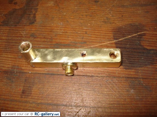
I made a banjo shaped holder that fitted around the router nose and was put into a QCT. All you need then is a fixed diamond dresser to trim the stone parallel to the lathe bed.
If you have compressed air, I have seen cheap pneumatic die grinders used to good effect as a toolpost grinder, again, these have a well supported nose, designed for sideways pressures, also the pressure can be reduced for slower running with a larger outside grinding wheel. Not that you use a lot of sideways force, in fact there should hardly be any, it is just the rigidity you are after, usually lacking in small hand held mini drills.
You are supposed to run the stone in opposite directions when doing either internal or external grinding, my commercial grinder runs in both directions by flicking a switch. You can get away with it by running the lathe chuck in reverse.

John
 
Thanks John, I have an old angle grinder that the ring gear in the head went out on. What RPM would be optimal?
Tim
 
HI

And the story goes on...

some of you may have noticed the loco in the background of the boiler pictures.
That will be a german BR 38 / P8 but to complete, there is still a lot of work to be done.

However, i one day decided to try a locomotive boiler before building the one for my steam loco. I have made a lot of pictures while building it but you can see it below:

347_854898eb0b58b0ddec865cd632383e37.jpg


347_7b3c64d120db8a6485470184fe02b267.jpg


When driving, i always had one piece of sheet on the mold and two cooling down from annealing.

347_3b2d4257b9ebd0c6bec1fdd83ec1c6e0.jpg


347_cb413487939a3513eba6af67d57974cf.jpg


This is the production of driving and annealing for about 6 to 8 hours.

Florian
 
And here production of the fixings:


347_9aa035ea478cdec72e0703a78164b5a3.jpg


347_515ebe80adbb86ebd8d012aa95da47af.jpg


That's going to be the blower valve.


347_f72fbec126c731149bd273b8c9e4a613.jpg


And here the whole assortment...
 
I am shure you were waiting for this: ;D

347_c7e10913c7ce29e6a01fcbe22083de4f.jpg


347_b542af2321cbb723cb72f9d128868439.jpg


347_d3394587a9d0fee4f3d4ec2a73a21955.jpg


347_9cc0257e937488c2f2c03c5fed45abfe.jpg


347_89c85073baa0f01e23ade087ce1c32a8.jpg


Up to here, i had no fitting pressure gauge so i adjusted the safety valve with an external one. Then the pressure could not get higher than 2 bar
 
Up to here i just fired the boiler with the blower. I first needed to make a nozzle for the exhaust steam.
 
Back
Top