Snow Tandem Engine

Home Model Engine Machinist Forum

Help Support Home Model Engine Machinist Forum:

This site may earn a commission from merchant affiliate links, including eBay, Amazon, and others.
Kevin: Thanks. Got any further with the Hog?

Steve: Thanks for the tip, think I'll go with it. I've messed around for years with linseed and shellac, but never yet tried tung oil.

Joe
 
Joe,
I'll have to second the tung oil. I've used tung and linseed oils on teak for my boat. I much prefer the tung. It dries much quicker than linseed and I think has a slightly deeper finish. After it dries I use a furniture polish that is heavy on beeswax for a little extra UV protection.
 
Hi

Having decided to take Steve's and Kevin's advice, here's the base with the first coat of tung oil. Man o man, should have found this stuff a long time ago....thanks for the tip, guys!
100_2820.jpg


This is the other bit of wood-working on the go, I'll finish it with the same stuff. If I ever build a Duclos/Cedge Victorian, this is the table it will sit on!
100_2822.jpg


All out of the same cherry tree, George Washington eat your heart out!

Cheers, Joe
 
Beautiful Joe...that cherry tree gave it up for two very fine causes :)

Bill
 
Joe....
No need to go to all that trouble.... if you really want a Victorian sitting on that table, just ship it on down here....LOL Beautiful work!! I've not gotten the touch for working with the brown stuff beyond the odd engine base or so.

Glad the tung oil worked out for you. I love the stuff. Very forgiving and the finish is as tough as Rhino hide.

Steve
 
Bill: Thanks! Steve: you'll have to get in line... the Mother in Law was over for supper this evening, and almost left with the table.... both the table and the base for the engine have had numerous coats of oil, and have been declared "done". That so, back (finally) to some engine stuff.

Picked up where I had left off, with plumbing: here are the bits for the exhaust manifold, straightforward turning for the flanges, and used the tubing bender I built a little earlier for the first time for real...
100_2830.jpg


Instead of building some complex jig for soldering, used the engine it's self: first the curved pipes into the flanges
100_2831.jpg


and then the bottom end of the curved pipes into the straight section of the manifold
100_2832.jpg


still got some cleaning up to do, excess flux and a few spots with some wayward solder to remove.

Cheers, Joe
 
The exhaust pipes sure came out well, Joe. Very neat and uniform.
Kind of reminds me of headers on a car engine.

Thanks for the new update. I always like seeing new stuff for this great
looking engine.

Dean
 
Thanks, Dean. Gotta admit that I quite like the "look" too!

Tried out the fit of the exhaust manifold with the coolant return in place, and was not at all pleased, the curved pipes of the manifold were just touching the coolant return pipe.... not visually pleasing at all. so, faffed around for the best part of a week, made new dies for the tubing bender to try to form a tighter curve for the manifold pipe (in several sizes) and used up all the tubing I had on hand with no useful result... so then went with plan B, and put an "s" bend in the coolant inlet and return pipes, and it looks a lot better to me now.
This will change the size of the outlet pipes from the water jacket, no biggie. :idea:

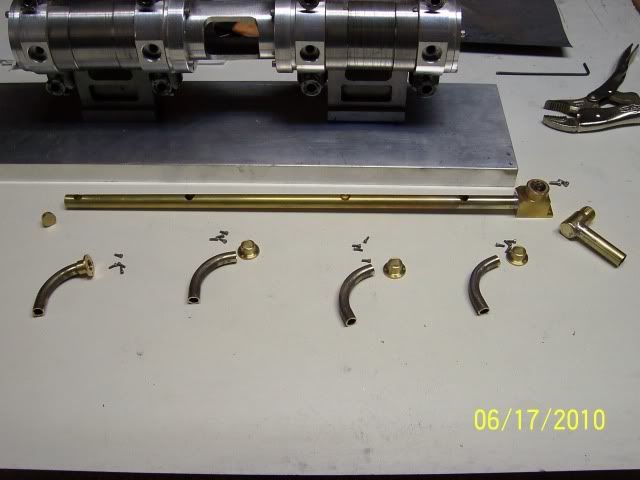
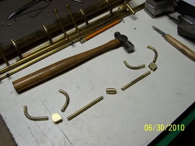
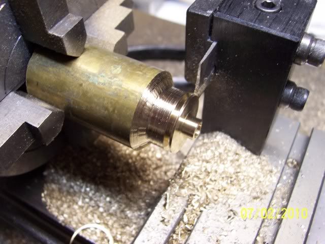
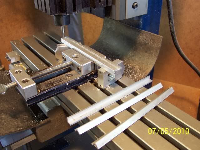
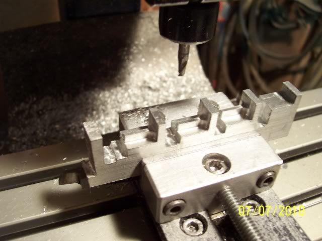
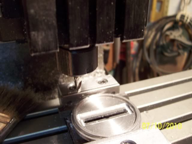
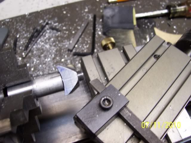
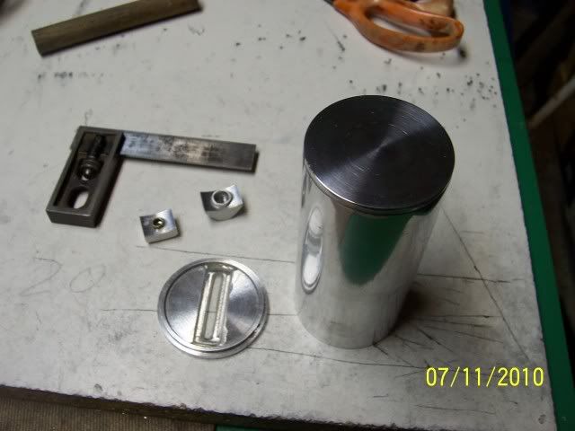
That done, moved on to the fuel intake manifold. First up: cut a little piece off of my secret stash of 1/2" brass..
100_2834.jpg


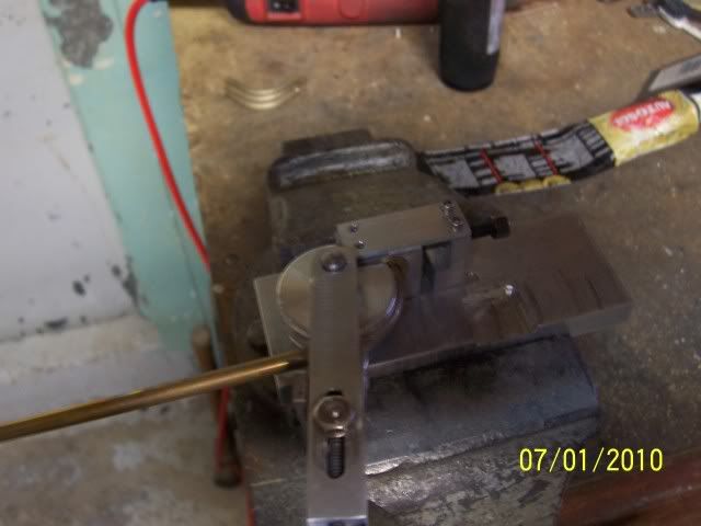
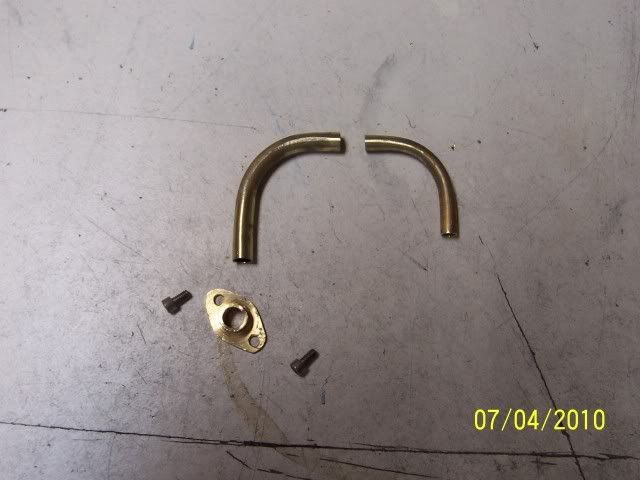
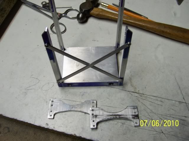
after a little milling & drilling, cut and bent some tubing, and here are the bits
100_2835.jpg


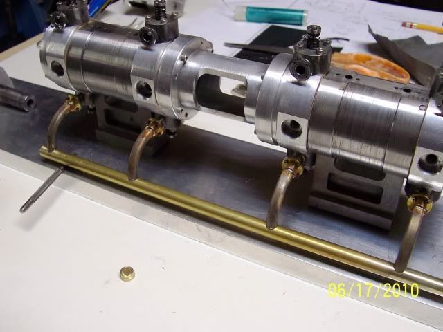
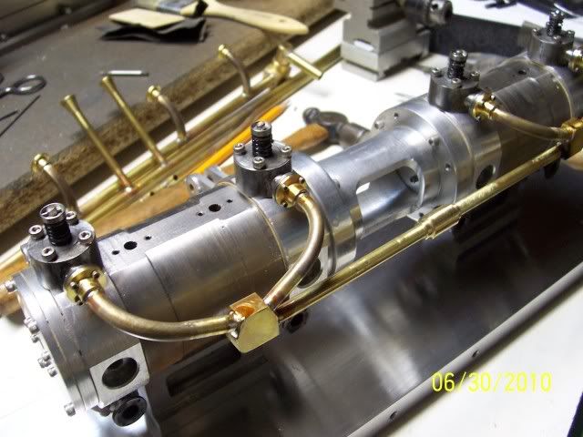
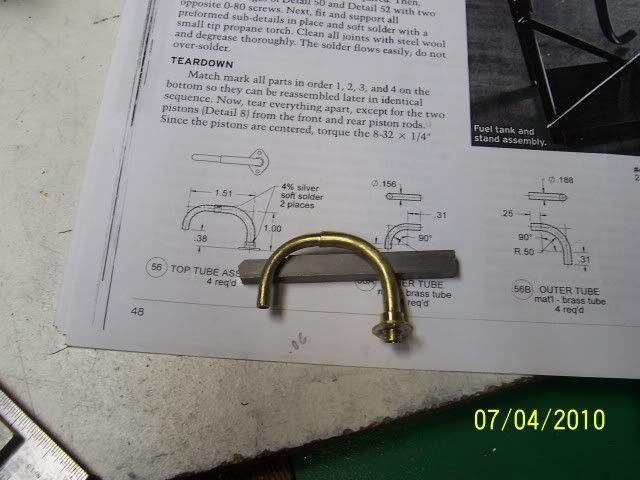
Again used the engine as the soldering jig
100_2836.jpg


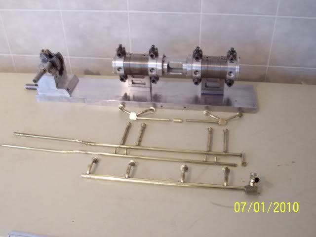
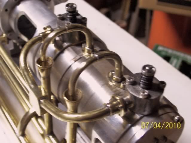
and here's all the plumbing done to date,
100_2837.jpg


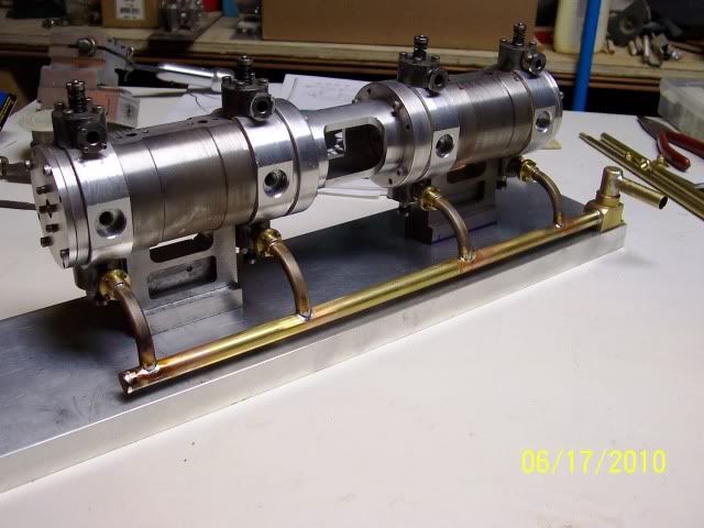
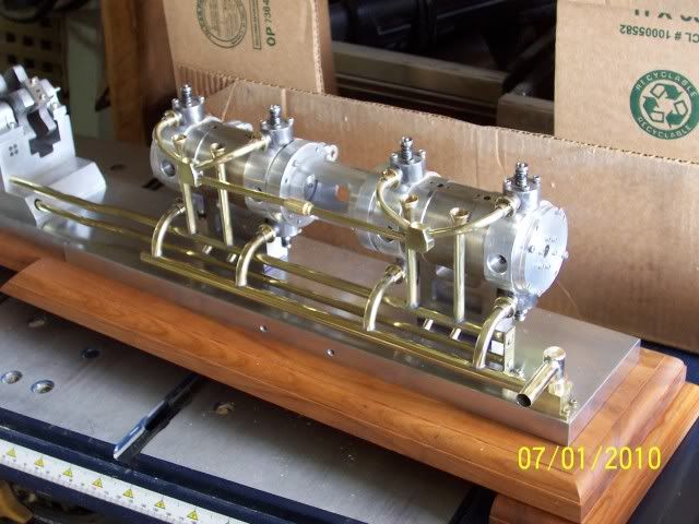
and, couldn't resist sticking it all together to have a look
100_2839.jpg


The fitting in the centre of the intake manifold still needs a bit to hold the carb, I'll make it to fit the carb once I've acquired one...
otherwise in plumbing only got the 4 little bits left to do that return the coolant from the water jacket to the coolant return manifold

Cheers, Joe
 
Gosh, Joe, that looks very impressive. Almost Duesenberg-like.
It gets more beautiful with every work session.

Dean
 

Thanks, Dean.

Kevin: (Ksouers) Way back in April you asked this question:

ksouers said:
What are the funnels for?

Well, finally, here's the answer...
Turned some brass to make flanges
100_2842.jpg


Bent some tubing with the shop-built tubing bender
100_2841.jpg


Here's all the parts together, shaped the flanges by hand with a file, seemed like way too much mucking around to machine it for four pieces whose only critical point is the fit of the tubing
100_2844.jpg


soldered together,
100_2845.jpg


And here they are in place. Coolant from the water jacket exits through these assemblies, squirts into the funnels to return to the coolant tank.
100_2847.jpg


Fuel tank or coolant tank next, haven't quite decided...

Cheers, Joe
 

Man, that's some serious plumbing going on there,

Nice work Joe!

Looks great.

 
It's quite a water works, Joe. We'll even be able to see the coolant circulating!

Dean
 
Joe,

It looks like you are a great pipe fitter.

How did you expand the ends of the tubing?

Keep up the good work.

Regards,

SAM
 
Kevin (KB) and Dean: thanks, guys. Sam: did the flared ends the (to me) easy way, turned some larger stock with an internal and external taper, and soft-soldered them in place. Hmm... flaring tool.... oh no... PROJECTITIS. another one for the list...

Cheers, Joe
 
Joe,
Nice plumbing work. My wife wants a new bathroom, are you for hire?? ;D

Thanks, the funnels work the way I envisioned from your previous description. It should be interesting to see the water dripping into them and the steam rising.
 
ksouers said:
Joe,
Nice plumbing work. My wife wants a new bathroom, are you for hire?? ;D

Kevin: Re-did the bathroom here 7 or 8 years ago... ripped it all out down to the studs, new drywall, plumbing, fixtures etc. I'll be entirely happy if I never have to do this again :big: Temporarily put the old tub in the garage with the tail pipe over the floor drain, ran some hose from the laundry room so's the missus could have her bath... didn't mention how tempting the automatic door opener was until AFTER the new bathroom was in use ::) ::)

now back to an engine...

Got going on the fuel tank assembly. Needed some 1/4" ali angle, only had 1/2" so milled off the extra bit
100_2850.jpg


the base is just a bit of ali with a few holes drilled & tapped, here's where that angle goes, and the start on the cross pieces that will hold up the tank
100_2851.jpg


decided to make some brackets for the u-bolts that will secure the tank. The plans had simply called out bending over a little tab on each side of the cross piece, but that would have been too easy. Set up a piece of ali in the mill, and did everything I could in that set up
100_2852.jpg


then parted them off
100_2854.jpg


a little fussing about with some files, and here we are
100_2860.jpg


Now I need a tank to go on the base, started out by truing up the ends of a bit of tube
100_2857.jpg


and that's where it is at the moment. Not sure how much will get done in the next little while, Number One son is due home on leave from the Navy on Saturday, so shop time will no doubt be curtailed.

Cheers, Joe
 
This is one spectacular build Joe - if I can get HSM Vol 25 No 6 (the others are still available as back issues) I'd like to have a go at it. Looking forward to your next progress pictures.
 
It is my understanding that Village Press has a book on the Tandem well along on the way to press. Not sure if it will be hard bound or one of the loose leaf types with the plastic spine, but either way you may want to wait for it to come out as opposed to finding the back issues.

Bill
 
Managed to get some shop time after all, so got a little further along with the tank..

Turned the end caps
100_2861.jpg


The plans call for one end to made of lucite in order to see the state of the fuel supply. I didn't much care for this idea, so instead I've milled a slot for a rather more discrete fuel gauge
100_2864.jpg


Then started on the bosses for fuel in and fuel out.... they need a radius to match the tank, so set them up on the face plate and not only did two at once, balanced the load on the lathe too!
100_2865.jpg


Once done with the radii, turned them around in the four-jaw, and drilled them through, and added a very slight counterbore, and tapped the filler boss
100_2866.jpg


the fuel out boss was just finished off with a hacksaw and files, but the filler boss got a little turning...made up a quick & dirty mandrel with the matching thread, and cut a taper on it just for the look of it
100_2869.jpg


Here's the state of play tonight: stuck little bits of pipe in the counter-bores in each of the bosses, these will serve to locate the bosses in place on the tank so they won't slide around whilst waiting for the glue to dry, glued a bit of clear Plexiglas in the slot for the fuel gauge, and glued the blind tank end in place.
100_2873.jpg


Still have to drill the holes for the bosses, stick'em in place, and then can locate the other tank end with the slot vertical in relation to the bosses... also have to make the filler cap (again) and (again) as so far there are two failed attempts in the save it for another possible use bin.....

Cheers, Joe
 

Latest posts

Back
Top