Snow Tandem Engine

Home Model Engine Machinist Forum

Help Support Home Model Engine Machinist Forum:

This site may earn a commission from merchant affiliate links, including eBay, Amazon, and others.

So close...

That pump turned out slick!

Have a good vacation.
 
Everything's coming together very well, Joe. It's at the point where I don't want to wait, but
have a nice vacation, anyway! ;D ;D

Hope you enjoy yourself!

Dean
 
Joe, Have a great vacation, Ithink you have done a great job on this engine. larry
 
With Mjnfabrication.com being out of business, where would you get a distributor for the Snow? Or would you have to go electronic and build your own?
 
Kevin, Dean, & Larry:

Thanks, Guys! Vacation is going well so far, spent Saturday at a retirement bash for an old Navy buddy, we were Acting Corporals together at Recruit School a very long time ago...going to the Montreal Casino today with the Mother in Law to celebrate her 80th...
will be sneaking in some shop time later whilst bemoaning how much stock I could have gotten if the loot could have been given to the local metal merchants instead :big:

SkyMoCo: A while back, (post 100 of this thread) it was mentioned that Roy was going to start stocking the Satra distributors. I don't know if he has, don't see any mention of them on his site http://www.cncengines.com/index.html you could certainly e-mail his to check it out.

Cheers, Joe
 
have successfully worked in some shop time already:

started with the bases for the oilers; turned a short spigot, threaded it with a die, drilled through 1/16", and turned down the rest and parted them off, threaded the other end in the vice with a die
100_3228.jpg


the caps: drilled & tapped, then counterbored, then shaped the other end and parted off
100_3229.jpg


cut some plastic tubing for the "glasses", a little tip for cutting flexible tubing relatively straight: bung in a bit of stock close to the ID and then cut around with a hobby knife
100_3231.jpg


assembled:
100_3230.jpg


and where they belong:
100_3235.jpg


Cheers, Joe

(and incidentally, broke even at the Casino, and somebody else picked up the lunch tab, so not so bad after all!)
 
Excellent tip on cutting the tubing straight, Joe. Thanks!
The oilers look great. Every little step now makes this engine look
better and better.

Dean
 
Sam & Dean: (sounds like an early sixties pop group....) thanks for looking in.

Got the cams out of the way...

trued up a chunk of steel in the lathe, drilled & reamed for the cam shaft, popped in a temporary dead centre, and cut a little deeper than the minor dia with a parting tool, this way once all the other machining is done, I can can come back and part them off without an interrupted cut
100_3236.jpg


off to the mill to whittle away everything that doesn't look like a cam... used a fly cutter, and rotated the stock a very approximate 10-15 degrees per cut,
100_3238.jpg


cleaned it up on the belt sander to remove all the little facets left from the milling, and them back in the mill for drilling and tapping for set-screws
100_3239.jpg


then back in the lathe for parting off, easy-peasy to pick up the original parting cuts
100_3240.jpg


and then some fairly finger-numbing cleaning up with numerous ascending grits of sand paper...and ta-dah: some cams!
100_3241.jpg


This thing is soooo close... I've got to make or acquire a carb, make the fitting to attach said carb to the fuel intake manifold, cut 4 gaskets for the coolant outlets, install the fuel line, and.... and..... dang, nothing else left to machine! The rest is all assembly.

(Of course, then the re-making of some parts will no doubt ensue....)

Cheers, Joe
 
And another slick trick by Joe! Partially parting the blanks before you profile them is
just plain ol' darn good thinking!
Thanks again, Joe. Yeah, the cams look great, too!

Dean
 
Thanks, Dean.

Now then... whilst pondering carburation options, decided to get busy sticking together the wiring.... since I know essentially squat about engine electrics, this is being instructional...

in other words,,, HELP!

Here's a pic of the underside, and the base of the distributor
100_3242.jpg


The Ignition board has 9 terminals:
coil -
6 volt -
engine ground
points
LED -
LED +
spare
6 volt +
coil +

Now then: the coil (Exciter brand) has a red, a black, and a pair of white wires...
the distributor base has 2 terminals...(either side of the points)

So:
coil - : is the red or the black?
6 volt - : OK, engine ground: OK,
Points: two terminals on distributor... ground one to frame and the other one to the PC board terminal ?
LED -, LED +, Spare: ignore all three,
6 volt + : OK,
coil + red or black?

and then the two white leads: am I correct in believing this goes to the centre of the distributor cap? And since there is two, do I just ignore one, or gang them?

Cheers, from the engine electrically challenged Joe
 
Joe,
You have one of the last versions of the Exciter coils that had 2 high tension leads (white). They can both be used at the same time for an engine that requires them, other wise ground one of them. (-6volts) The other two wires on the coil are red, coil + terminal and black , coil - terminal. The one marked points goes to the insulated terminal on your points. Engine ground is self explanatory, it goes to the engine frame. The LED terminals are for an LED lamp which is useful for timing purposes. It sounds like you are using a Jerry Howell ignition and an LED is usually included with the set. The LED has 2 leads, the long one is positive and the short one is negative. The one that you call spare is for when or if you would use a Hall trigger instead of the points setup but we'll leave that for another day.
gbritnell
 
Thanks, George.

Much clearer now. Only two questions for now: both terminals for the points are insulated on the body of the distributor (Satra) ; so I can just randomly pick one to connect to the PCB and ground the other? As well: does this require high-tension wiring, or will some 22 ga hook-up wire do the trick?

cheers, Joe

(edited to add yet another question....)

 
Vacation's over, the stairwell to the basement has a new coat of paint, and I'm back in the shop...

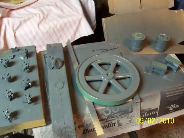
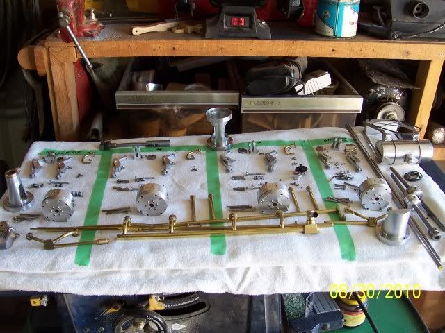
Masked, primed, and painted all the parts that are supposed to be painted. Slow job, couple of minutes painting, wait a day, repeat...
100_3271.jpg


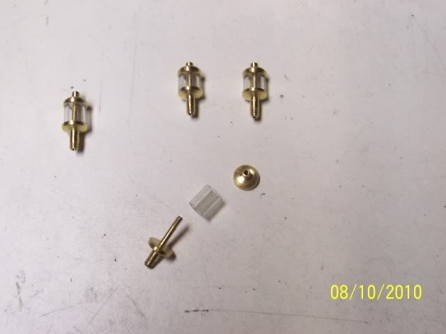
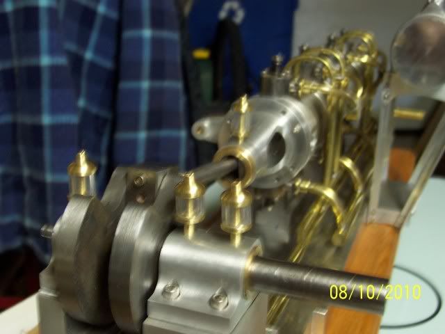
and here's pretty much all the other bits:
100_3269.jpg


and then started on a carb. I'd been faffing around trying to decide on buying or making one, finally decided to make one.
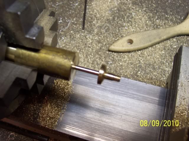
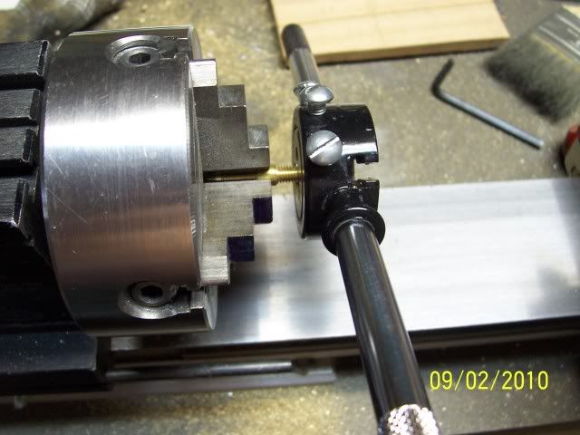
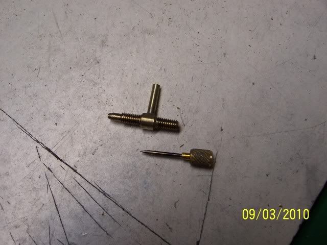
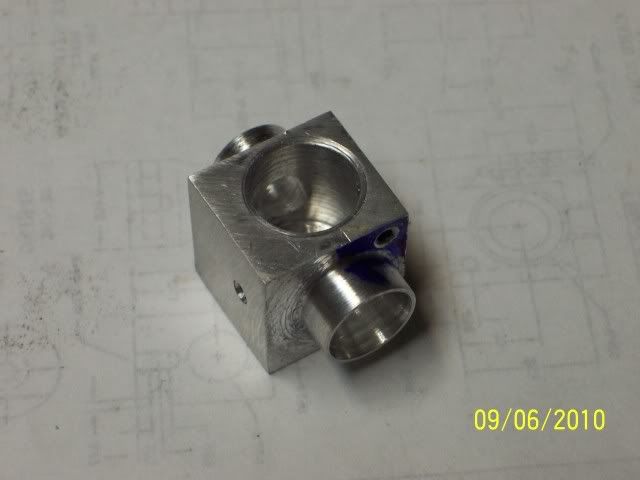
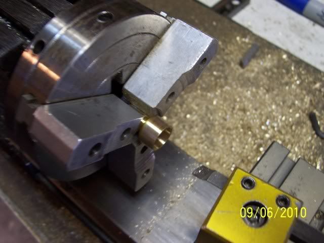
I'm using the plans from George Britnell's 4 cyl OHV. Started out with the needle valve body, turned one end and threaded, turned it about and same again, and drilled almost through from the end
100_3272.jpg


then turned about again and drilled the jet: had that 4 jaw spinning at 5800 RPM (top speed on this lathe) and it worked OK
100_3281.jpg


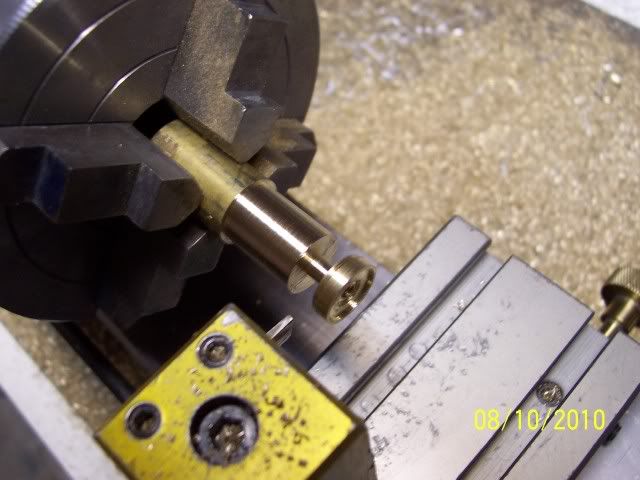
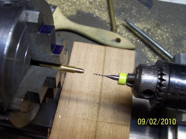
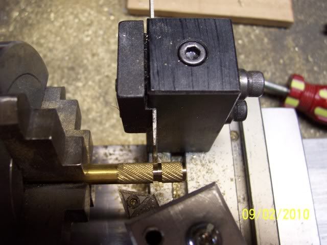
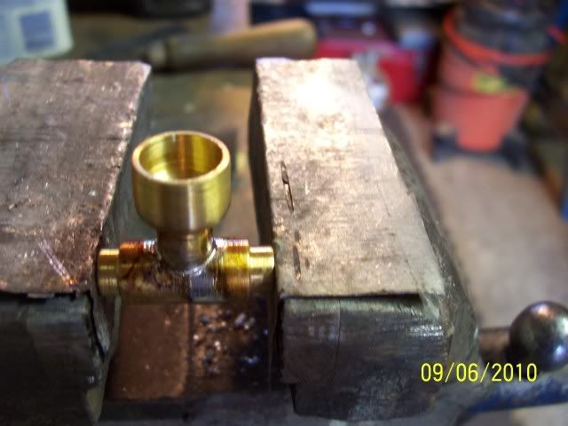
Then on to the needle: turned and threaded a bit of brass, drilled through for the needle, and turned down a length to fit inside the valve body, and parted it off with a little bit of threaded portion left
100_3276.jpg


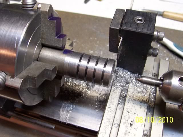
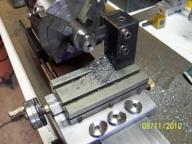
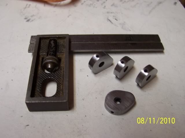
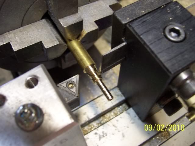
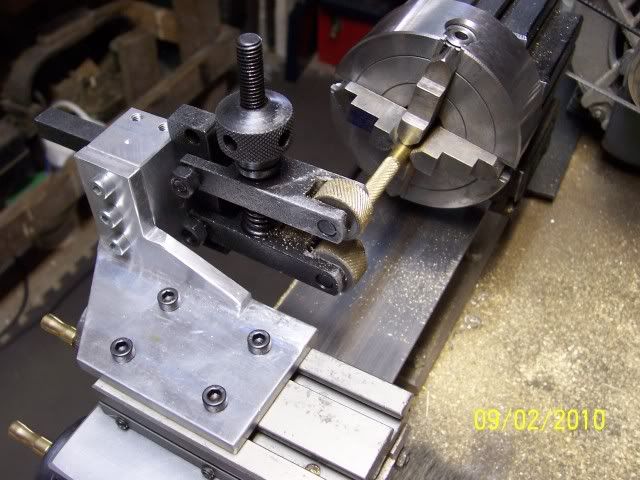
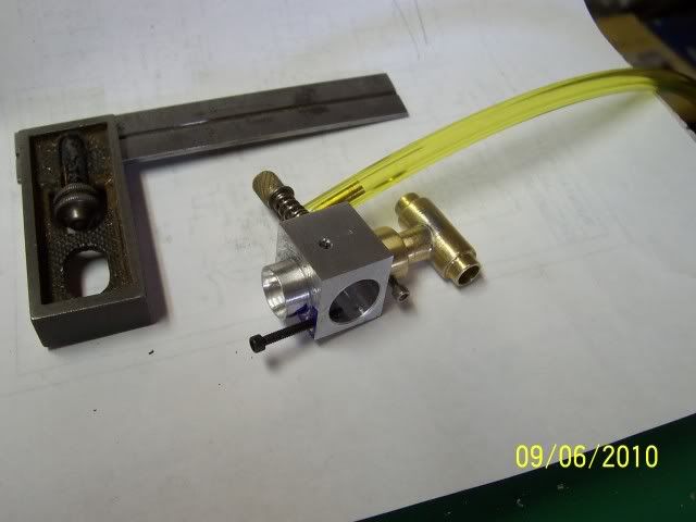
Rigged a tool-holder for my brand-new scissor knurling tool, and knurled a bit of brass rod (hadn't done this since high-school shop class, seems to have worked OK!)
100_3277.jpg


drilled and tapped, and parted off
100_3279.jpg


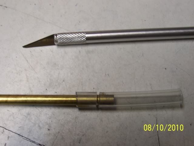
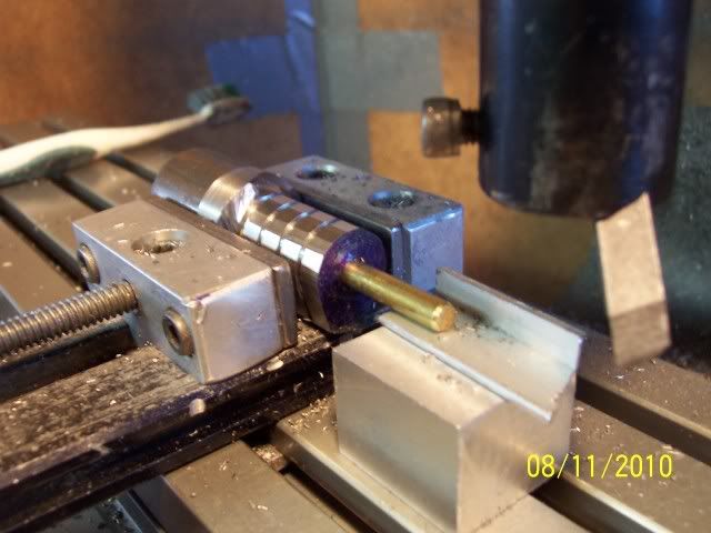
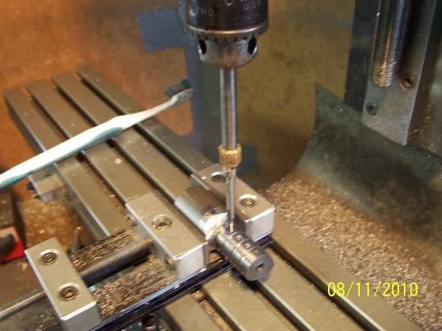
stuck a duly sharpened piece of music wire in the holding bit, screwed that into the knurled bit, and silver soldered the whole thing together. Polished up the end, and here we are.
100_3282.jpg


Now into the long week-end, so should see some more progress!

Cheers, joe
 
Good makins, Joe!
I see you broke down and bought something for a change, instead of building
it. Kind of rare for you. So, how do you like it, (the knurler!)? And, where
did you buy it?

Oh, and the tool holder you made for it looks great, BTW.

Dean
 
Hi Dean

Picked up the knurling tool at Busy Bee. It's worked OK so far,tried it on brass and some ali, haven't tried any steel yet. I was in Ottawa for an overnighter during my vacation, which conveniently has a Busy Bee store, Lee Valley Tools, and a Princess Auto... lots of shopping opportunities ;D the thing was on sale, I couldn't help myself. SWMBO was looking over the various iterations of SIEG lathes mentioning how "Too bad they're too big for your shop, Dear", she didn't seem to hear my reply of "room CAN be made". Oh well.

Cheers, Joe
 
Joe, this is an inspiring thread. I had missed the post on making the cams but like that procedure very much. I will only have two to make on my current project but will be giving that a try for sure. Thanks for sharing your techniques.

Bill
 
Bill: Thanks, and you're welcome!

Closing in on the end here... made up the carb body: squared up some ali in the mill, bored, drilled, tapped, turned bosses, taper-turned for venturi, neglected to take any "in progress" photos, so here it is done:
100_3289.jpg


with the dimension established by the body, I could now make the fitting to attach the thing to the manifold, turned, drilled, and bored
100_3285.jpg


soldered it to the the piece that joins the two halves of the intake manifold
100_3286.jpg


and here's all the bits where they belong:
100_3287.jpg


Still have to make the barrel, so, unless I've missed something somewhere, I have got

ONE PIECE LEFT TO MACHINE woohoo1

Cheers, Joe
 
Joe;
Like many others I'm silently following this thread - with my jaw hanging down on the keyboard... :big: Glad to see the finish line is in sight for you, I'm as keen as you to see it run!

I giggled when I saw your table of finished parts - with the "Les Nessman partition tape". Boy I hope you don't have any curious three year old's in your house....I grew up the oldest in a house of six kids so I can spot trouble/fun 20 miles away!!!

Could you tell me what you are using for parting off blades on the Taig - I've picked up a spare Taig tool post to use at the rear, but haven't yet acquired the blade. Any recommendations?

Cheers and good luck on the first run...

Garry
 
Back
Top