Snow Tandem Engine

Home Model Engine Machinist Forum

Help Support Home Model Engine Machinist Forum:

This site may earn a commission from merchant affiliate links, including eBay, Amazon, and others.
My first thought was "It'd sure have been nice to see a man standing next to it."

Then I saw him, little teeny guy hiding amongst that huge engine :eek:
 
Hi all

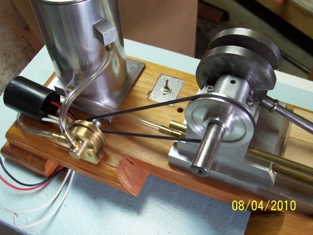
Got started on the coolant pump. The plans called for using a submersible electric pump in the reservoir, didn't much care for that, so after asking a few questions of Rustkollector (Jeff) decided to go with Jerry Howell's magnetic drive pump. Of course, I can't just follow the plans, so there have been a few modifications already... ;D ;D

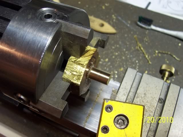
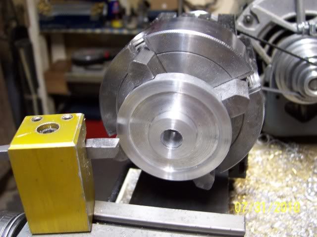
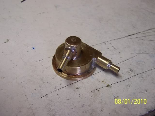
I didn't have an appropriate piece of round stock, so soldered a temporary spigot on a chunk of my secret stash of 1/2" plate brass, and then turned the spigot so it would run true
100_2905.jpg


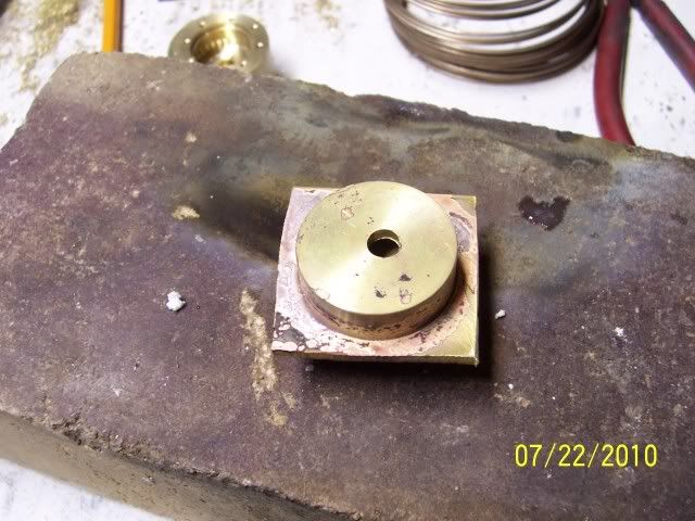
Turned it round, reversed it in the chuck and machined off the spigot in the process of hollowing out the piece, then silver brazed it to a piece of flat stock.. (I've been reading a lot of posts about silver soldering lately, so I greatly reduced the amount of silver solder as compared to my previous practice... seem to have gotten it just right. Thanks to all who have been posting tips on this arcane art!)
(and, if you look closely, just behind the firebrick you can see the first one, stuffed it up drilling the bolt circle....)
100_2908.jpg


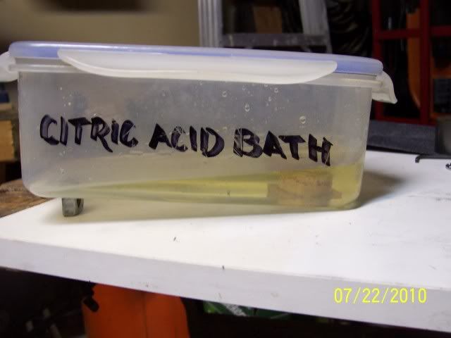
in the pickle.... looks like I need to top up the supply
100_2909.jpg


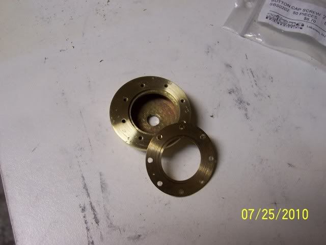
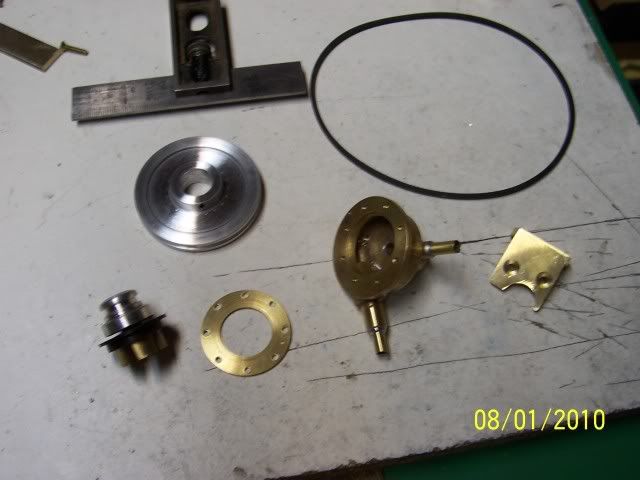
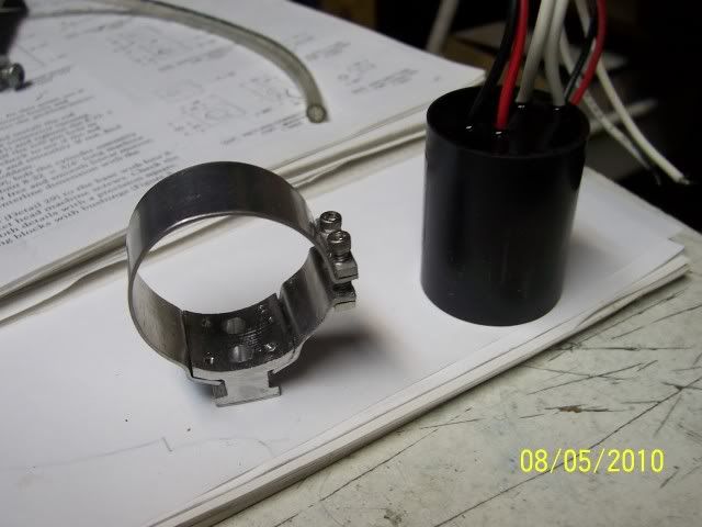
Jerry's plans call for a delrin piece threaded into the brass body to hold the impeller in place. I still don't have a thread-cutting lathe, so left the hole in the pump body un-threaded, will also not thread the delrin insert, and will hold it together with this clamping ring
100_2910.jpg


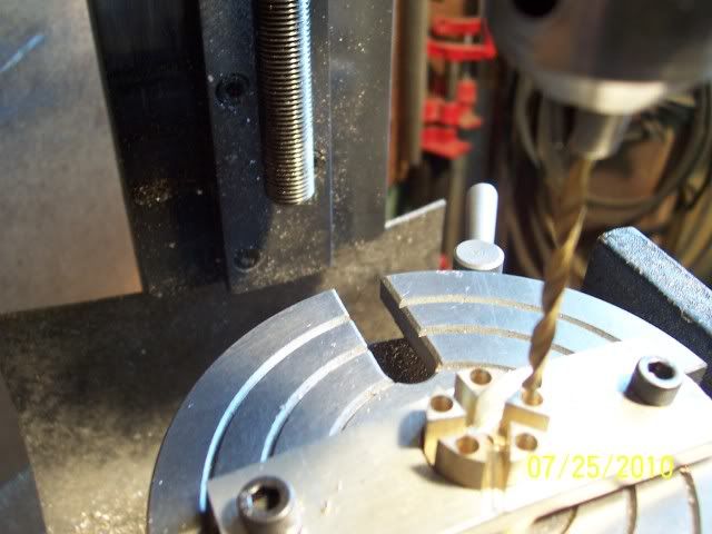
Next up is the impeller, turned the blank with a shoulder on the bottom to facilitate holding it on the rotary table with a strap of spare ali, off-set it to mill the slots, re-centred and drilled the holes for the magnets, after this re-chucked it in the lathe and turned off the shoulder
100_2914.jpg


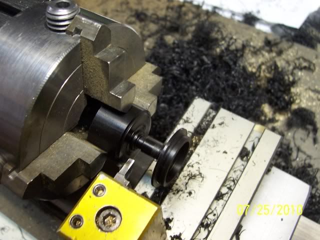
and here is the delrin piece ready for parting off. First time I've machined this stuff, boy it sure cuts easily with a nice finish. Nice soft non-cut-causing swarf, too :D
100_2917.jpg


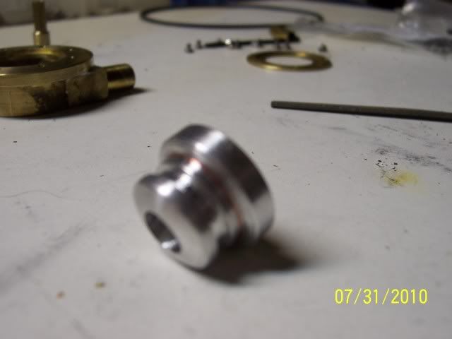
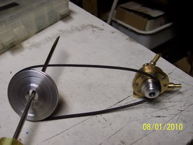
Made the pulley for the thing, and then added it to the pile of parts that don't fit, so next up will be another one.... and inlet & outlet bits.

Cheers, Joe
 
The pump housing looks neat, Joe.
So, the holes in the impeller get magnets, and when it's buttoned up inside the housing, and an
external thingy spins it via the magnets? Am I even close?

Dean
 
Deanofid said:
Am I even close?Dean

Yup. Yer close. Real close. In fact, pretty much right on the mark. :big:

This is one of those "how much of this do I show?" bits, Jerry Howell's plans are still copyright and available for sale....so don't want to go overboard with too much detail, but on the other hand, there are only so many ways to stick an impeller in a housing to move fluids...

Joe.
 
Dean: Better stop now while you're at 100% :big:

Hopeless: The only info I've seen on that has them being used on a pipe-line. Presumably could have been used anywhere one needed low rpm/high torque for long periods?

Got a bit further with the pump:


Turned the driven pulley that in turn moves the impeller. Looks like a real simple part, huh? This danged thing took me three tries: overbored the hole for the bearings in the first one, the tool grabbed the second one out of the 4-jaw and tossed it across the shop leaving un-recoverable dings, the third one came out OK
100_2966.jpg


Then turned the driving pulley, this one worked out first time ::)
100_2965.jpg


soldered the inlet and outlet to the pump body
100_3033.jpg


made up a mounting bracket, here it is with the rest of the parts
100_3034.jpg


And here they are stuck together.
100_3035.jpg


Still have to test it moving some fluid, and then mount it on the base of the engine.

Cheers, Joe
 
That looks very good, Joe.
No guesses about anything this time. Don't want to ruin my record!

Dean
 
Joe,

Nice looking water pump.

Are you going to perform a pump test and generate the pump curve.

SAM
 
Dean: You're still riding at 100% :bow:

Sam: going with the entirely basic empirical "spin it and see if it moves some fluid" type of testing... I've SEEN pump curves on paper, and cheerfully admit that the generation of such an animal is beyond my ken. (And the interpretation thereof as well ??? )

Joe
 
Dean, Just to make sure I understand what’s going on.
The Delrin is a bearing surface for the pulley which must be made of steel so the magnets in side are attracted to it and turn when the pulley turns. Even close????
 
Jeff, you'd better ask Joe about that. I don't want to ruin my perfect record!

Dean
 
Chicken, Dean? Rof}

Jeff: the pulley is called out as brass or aluminum, as it has a matching array of magnets countersunk in the inside rim to work with the magnets in the impeller. The whole point here to avoid the need for a through shaft with the ensuing sealing problems.

Cheers, Joe
 
Got it, Magnets on both pieces and No mechanical connection between the two.

Thanks!
 
Magnets!
Not chicken, Joe. I know they really do it with mirrors!
Ya can't fool me..

Dean
 
Dean: it's smoke and mirrors. Never forget the smoke....

Got the bench test done on the pump, we have circulation! Here's a very short video thereof...


Here it is stuck in place
100_3084.jpg


And with the flywheel in place. The clearance was dictated by the belt I had on hand.. sometimes ya gits lucky!
100_3085.jpg


the other side
100_3086.jpg


not much left now...

Joe
 
Joe,

Your magnetic drive pump is very nice.

For your pump test, see how high the water can be pumped.

The difference in elevation between the suctions liquid level and the height of the discharge liquid will give you the feet of head. 2.31 ft of water head is equal to 1 psi.

You can also measure the volume by pumping from or to a graduated cylinder to determine GPM (gallons per minute) or litres per fortnight. :big:

Regards,

SAM
 
Sam

Thanks for that! I had no idea how to quantify the output. Now, of course, I'll have to try that out....

In the video it was running with a 2" drive pulley at 500 rpm. When I increased the speed to a nominal 880 rpm, the output stream was going markedly further with greater pressure... now I can put some numbers on that... thanks again, much appreciated.
This sort of input is why I like this place Thm:

Cheers, Joe
 
Thanks, Richard.

Needed to tie down the coil next to the pump, so made up a clamp on a foot that screws down on the wooden base
100_3106.jpg


and here's things no longer flopping around
100_3109.jpg


Things are likely to slow down a little bit, as I'm on vacation as of tomorrow evening, and will be in and out of town for the next two weeks. Shop time will happen, just a little intermittently.

Cheers, Joe
 

Latest posts

Back
Top