Small V8

Home Model Engine Machinist Forum

Help Support Home Model Engine Machinist Forum:

This site may earn a commission from merchant affiliate links, including eBay, Amazon, and others.
Hi Steve,
The crank looks great. If you want to cut the counterweights it's actually quite simple.
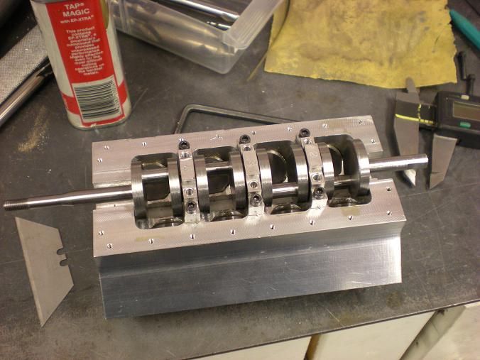
Make up a fixture plate that replicates the crankcase. The slot for the mains doesn't even need to be round. Make it so about .015 shallower than the diameter of the mains. Make the pockets deep enough for the radius of your counterweights. Drill and tap sets of holes at the webs and make small retainer straps to go across them. Now just bolt in your crank and cut the webs however you want them. I really don't think cutting stock away will affect the balance or centrifugal weight on something this small but it makes it look way cool.
George
 
gbritnell said:
If you want to cut the counterweights it's actually quite simple.

After 5 failed attempts, I think this one will stay the way it is. I don't want to screw it up now. Maybe the next one.


metalmad said:
Id be a bit warey of parting off between centers mate

I would never do that. I was going to grab it with a 4 jaw and part off at the lowest speed possible. Done it many times and it works good and I can get it to the correct length this way.


Thanks !!


Looks good Steve. I just knew you'd get it. :bow:

Ron
 
You use carbide lathe tools? I never had a lot of luck with carbide lathe tools. They never seemed sharp enough to me. I think carbide lathe cutters cut differently than sharp HSS tools. I think they place a much larger load on the work.
 
jpeter said:
You use carbide lathe tools? I never had a lot of luck with carbide lathe tools. They never seemed sharp enough to me. I think carbide lathe cutters cut differently than sharp HSS tools. I think they place a much larger load on the work.

It depends what i'm doing. If you are able to spin the heck out of the piece then I use carbide. If I need to turn low speed like a crankshaft flopping around offset, then HSS is what I use. Also if I have alot of material to remove then I think the speed is with carbide.
 
The crankshaft is safe in it's new home. I made the main bearings and installed the shaft. It is a bit snug but it will seat itself in no time. There's going to be a party tonight.


DSCN1070s.jpg
 
Hi Steve,
I'll bet it's like a ton was lifted off of your shoulders. It's frustrating to have to do things twice or more to get the desired results. Although you didn't use spacers when you cut the first one, for safety sake I would recommend using them for the other 2 cranks. It just prevents any longitudinal bending from happening.
Are you going to start on the other cranks right away or move on to some of the other parts first?
George
 
gbritnell said:
Hi Steve,
I'll bet it's like a ton was lifted off of your shoulders. It's frustrating to have to do things twice or more to get the desired results. Although you didn't use spacers when you cut the first one, for safety sake I would recommend using them for the other 2 cranks. It just prevents any longitudinal bending from happening.
Are you going to start on the other cranks right away or move on to some of the other parts first?
George

To be honest G, It didn't bother me all that much. I guess I expected it wouldn't be all that easy. I did the Peewee crank but this one is over 2 inches longer. Now I have to decide weather to make another one piece or do a 5 piece. It would be nice to include that as an option in the drawing set.

I think I'm going to keep on trucking and get one completed. I will continue to make enough parts for 2 complete engines. When the time comes that I feel like doing another crankshaft, I have 2 blanks sitting on the bench ready to go.

Thanks!!
 
If it turns half way free it must be straight. Along the way I've made a few that weren't so straight. It took me a few to work out the bugs. Good job. Did you mill any of it or turn it all?
 
jpeter said:
If it turns half way free it must be straight. Along the way I've made a few that weren't so straight. It took me a few to work out the bugs. Good job. Did you mill any of it or turn it all?


It's just a little sticky. I can turn it with the 1/4 inch shaft it just gets a little tight in one spot.

I mill about 80% of it. I mill all the centers and rough them. then I mill and finish the throws one at a time. Then go back and finish all the centers.
 
Hi Steve,

Did you use "Collonna" Style bearings?..... th_wwp ;D


Dave
 
steamer said:
Did you use "Collonna" Style bearings?..... th_wwp ;D

Don't know what a Colanna style bearing is.

I made bronze insert style bearings. The second and fourth bearings are just a split ring. The center bearing is a split ring with flanges on both sides to control the end play. I just put 2 pieces in a 4 jaw and made the bearing. I didn't even solder them together. Just mark them some how before you part them off so they can be reassembled the correct way.

Sorry about the lack of photo's but this crankshaft required more than the normal amount of attention.
 
Ron uses them on his Offy. Their .010" thick pure silver sheet.

He didn't dream them up, but he's made them somewhat famous...... :bow:

Dave
 
Awesome day in the garage today. I made the flywheel which is nothing more than a big slug of steel. It is bolted onto the crankshaft with a 10-32 nut or i chose to make the optional output shaft. Never know but I might want to power a pencil sharpener or a blender to make margeritas at the next NAMES show.

DSCN1073s.jpg


DSCN1074s.jpg


Started on some pistons. Machined up the blanks and put the grooves in. Then the parts were rotated and the blank was faced to size. I also machined a boss to hold the piston until all the machine work is done. My bore is .6245 so all the blanks are between .6230 - .6235.

DSCN1077s.jpg


DSCN1081s.jpg


DSCN1083s.jpg


DSCN1087s.jpg
 
Made a few more parts. I couldn't find a cool looking oil drain screw so i made one. I didn't want just a plain hex head screw.

DSCN1106s.jpg


I also made a PCV valve. I'm not to sure it will do anything but what the heck. It is a stem with a cap. In the stem is a 1/8 inch ball and a spring to help seal when the crank case goes negitive.

DSCN1109s.jpg
 
Hi Steve,
I have found that some type of crankcase ventilation is necessary. It's not just for the positive and negative pulses but there is always a little blow by and it helps to keep it from weeping out somewhere else.
Something else you might consider is some way of measuring the existing oil level, either through a dipstick or a level plug. It makes it a lot easier than guessing how much oil is in the engine.
George
 
gbritnell said:
Hi Steve,
I have found that some type of crankcase ventilation is necessary. It's not just for the positive and negative pulses but there is always a little blow by and it helps to keep it from weeping out somewhere else.
Something else you might consider is some way of measuring the existing oil level, either through a dipstick or a level plug. It makes it a lot easier than guessing how much oil is in the engine.
George


I have plans for a dip stick. I have been putting it off but it must be done.
 
I mounted my chuck on my rotory table and ended up with .0007 runout. I have never been that close before so im trying to get everything done that requires rotation before I take it back off to do some CNC work.


Started on the distributor body. The part started out as a 1-1/5 inch round bar. Made some cuts until I ended up with this.

DSCN1090s.jpg


Then I made the slot between the body and the hold down flange.

DSCN1092s.jpg


The end was drilled thru and the bearing pocked was bored.

DSCN1094s.jpg


DSCN1099s.jpg


Went over to the mill and cut away everything that wasn't hold down clamp. Then the slot was cut for adjustment.

DSCN1101s.jpg


DSCN1102s.jpg


The piece was then put back in the lathe where the top was finished to 1 inch. The recess was bored and the top bearing pocket was formed.

DSCN1105s.jpg


All that is left now is the largest diameter needs to be milled away to form 2 holding tabs to secure the cap onto the distributor.
 

Latest posts

Back
Top