Lakc said:Awww its an ittty bitty dominator. ;D Too cute!
Yes it is and I expect to see a little Weber on your's!!


Lakc said:Awww its an ittty bitty dominator. ;D Too cute!
kcmillin said:Wow, this thing just gets cooler and cooler.
That carb is awesome.
Is the air bleed in the idle circuit? I am trying to design a carb for my Tiny 4 cylinder, and would like to incorporate an air bleed into the main circuit with perhaps an emulsifying tube, but I can only find info on large carburetors, and I am thinking I might just be adding more potential problems.
Kel
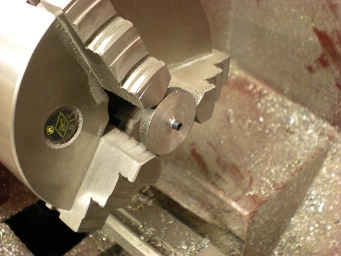
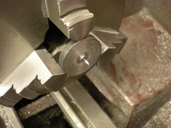
George_Race said:I am curious as to what kind of tooling you use to make something like the little carburetor shown in your recent post.
2 flute, 4 flute, end mill, ball end, carbide, HSS, diameter, etc...
Also, are you hand milling everything? Do you use CNC for some? What is your milling machine?
I don't live very far from you and wonder if there would be any opportunity to visit your shop, and see first hand your work in progress?
LongRat said:Does your design have space for a built-up crank? I mean the design with the large ball bearing mains. I wonder because there is certainly a following for them and some people might prefer to go that way, using your plans.
LongRat said:I know you say you are not a master machinist, but the pictures and previous builds paint a somewhat different picture.
stevehuckss396 said:The air bleed is a hole thru the body of the carb that leaks air thru the barrel when it is "almost" closed. All I did was put an adjustment screw between the hole and the barrel to make adjustments. When I did the Peewee, the carb had a tiny hole in it. The hole size is increased and test. Increase and test until it works good. Problem is, when you over shoot, there is no going back.
If you need some help or want to see what I did, I can try to post some pics of my bleed circuit.
kcmillin said:That would be awesome Steve. I need as much info as I can get
LongRat said:Steve, I fully understand. I am designing my 1st engine now. I am at the point where I think I know how far I can push myself while still ending up with something that works. I do not want to invest time pushing myself TOO hard. My enjoyment comes 50-50 from building and then running in practical RC applications. I offer my thanks to you and many other people on the board for inspiration and mostly, useful technical knowledge that only experience really gives.
A thought on the 1-piece crank. What about setting up the blank vertically on the CNC mill and using a slitting saw or T-slot cutter to rough out the bearing journals? Then you could transfer over to the lathe and do the finishing accurately, having got rid of most of the pain of the offset turning and intermittent cutting. It is a method I intend to try as I think a full camshaft could be done this way too, using a vertical CNC rotary table - possibly with a 'tailstock' to support the free end of the blank at the top (a special fixture would need to be made to achieve this). Then, grinding wheel in the mill spindle to grind the cams with pure X axis movement and synchronized rotation of the rotary axis.
jpeter said:I suggest you drill 5 centers in each end (First lay the stock in a tslot and mill a flat on each end for indexing). Next, chuck a piece of bar and turn a point on it for a live center; don't remove it from the chuck. Mount your blanked out piece from the mill between centers and rough out the mains. Then, turn the throws to final size making sure to dress the throws so you've got enough width for the rods. As a final step finish turn the mains. If your careful to not squeeze the crank to tightly you won't need to block the center spaces. Take it then back to the mill and mill away the counterbalance part of the throws.
I shouldn't even be telling you this cuz your work is as nice as I've seen. You should be telling me how to make a crank.

Enter your email address to join: