


- Joined
- Dec 5, 2009
- Messages
- 510
- Reaction score
- 47
Most of my engines used a spring tension valve system, so when the air intake stops the engines would stop rather abruptly,
my very first engine I ever built, and designed from scratch, was a double acting valve system, with scotch yoke connection for the valve.
When I apply air to it, it revs up very fast, and when I shutoff the
air intake, for a brief moment, the flywheel momentum goes rather strongly, so as air intake is applied and relieved, it gives a sound of an engine reving up, plus the air exhaust gives that puffing sound, so combining all that, I can make the engine sound like its reving up.
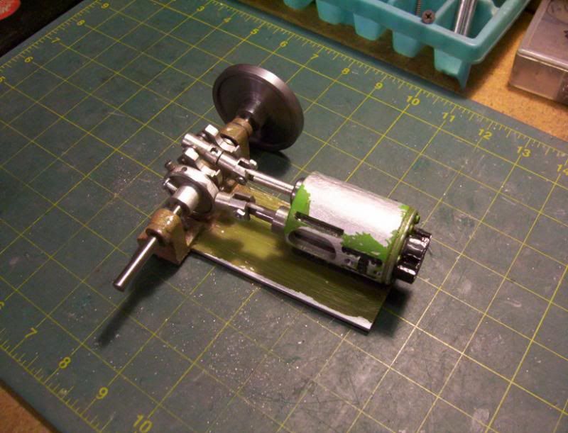
Now I just built a very quick one valving engine, with no spring tension for the valve system, but rather the classic eccentric/strap combination, this has a positive movement on the valve, both forward and backward in its cylinder, so with no spring tension, it has the ability to rev up and rev down with flywheel momentum, without stopping abruptly.
Here is that engine, I also built it as an experiment to see how painting my projects would work for me.
Now as I was playing around with my engines of late, I thought about building this same engine, since now I have all the location dimensions figured out for the valve holes, as well as the valve length, where it is machined at for the valving, the piston con rod length, and a few other major dimensions, already in working order, so with all this already established, I decided I want to build this type of engine again, only make it a twin cylinder vee design.
So here is the start of this engine build:
since this is designed to have both the piston cylinder sleeve and the valve cylinder sleeve, in the same round block, I needed to use my 1-1/2" round bar I have on hand.
This dictated the whole design of my engine shown above, If I had something of different size, the design would have gone that dirtection instead.
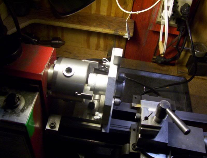
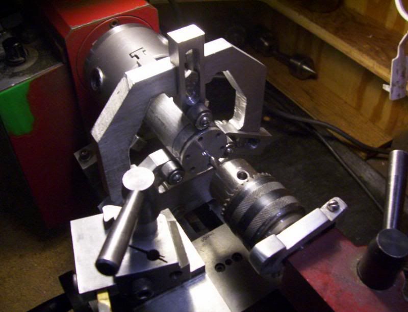
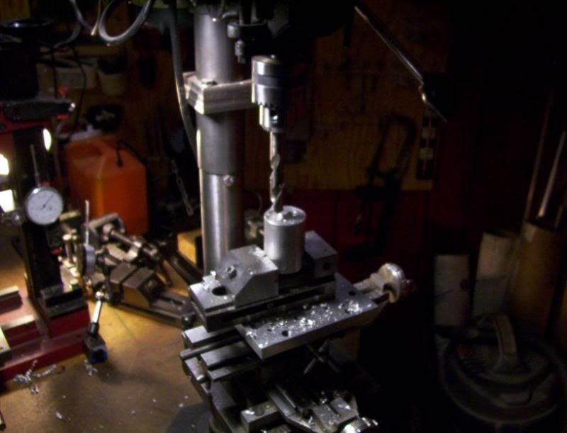
Because I am using a bar stock bigger than my 7x10 mini lathe steady rest could handle, I have to use my shop made steady rest to handle stock up to 2" in dia.
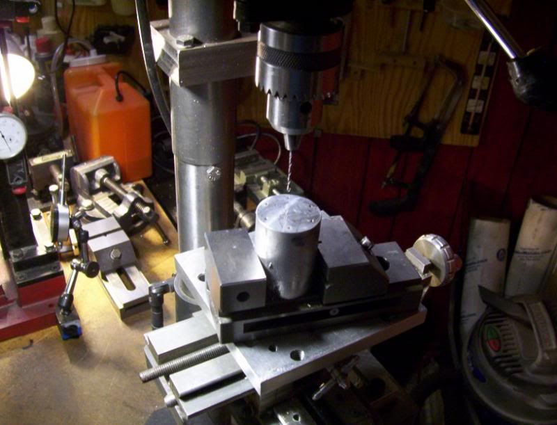
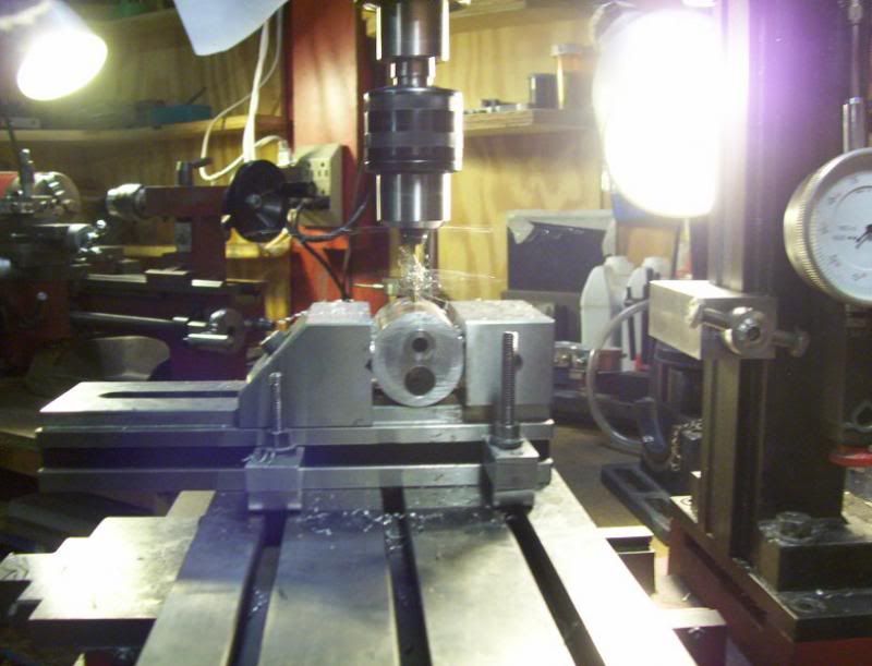
here is one of the cylinders housing being faced off to length, in the steady rest.
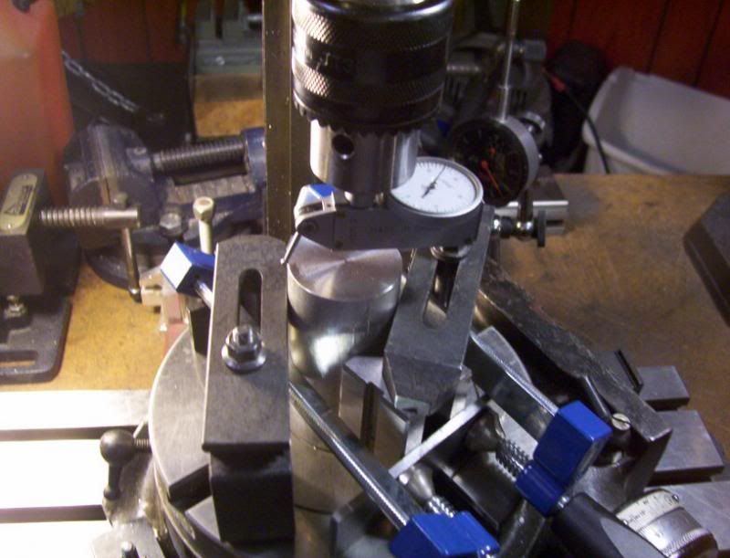
once they are machined to length, I need to drill 6 holes at 60 deg. on my rotary table, around the perimeter, these holes will be tapped to 2-56 thread.
So after some elaborate clamping to the vee blocks, I then proceeded to tram in the round workpiece to center of the rotary table.
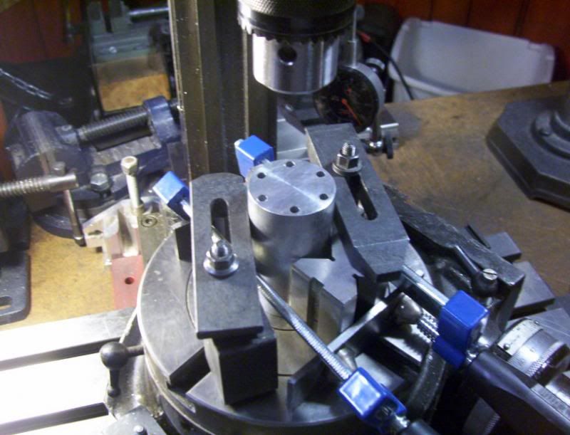
now all the holes were drilled at 60deg. increments, these holes were drilled a certain depth for tapping, then finished off with a body drill for a 2-56 screw to a certain depth for the screw to pass through part way. The reason for this is because I am going to cut this section away to be screwed back on as a cap, and the reason for that, is, because it is easier to drill and ream a through hole for the valve and piston cylinder sleeves to fit into, then to drill a blind hole.
The valve cylinder sleeve will go all the way through, but the piston cylinder sleeve needs to be capped off after the hole has been drilled and reamed all the way through.
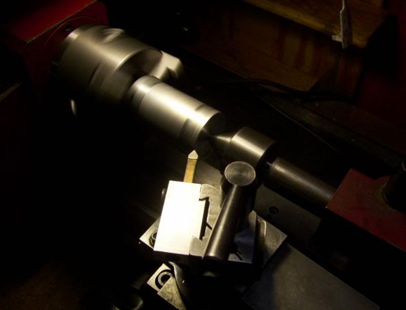
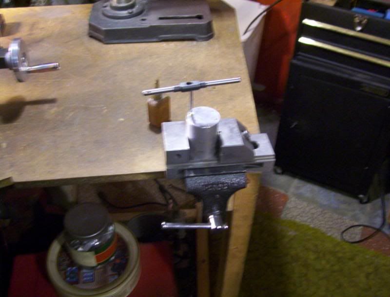
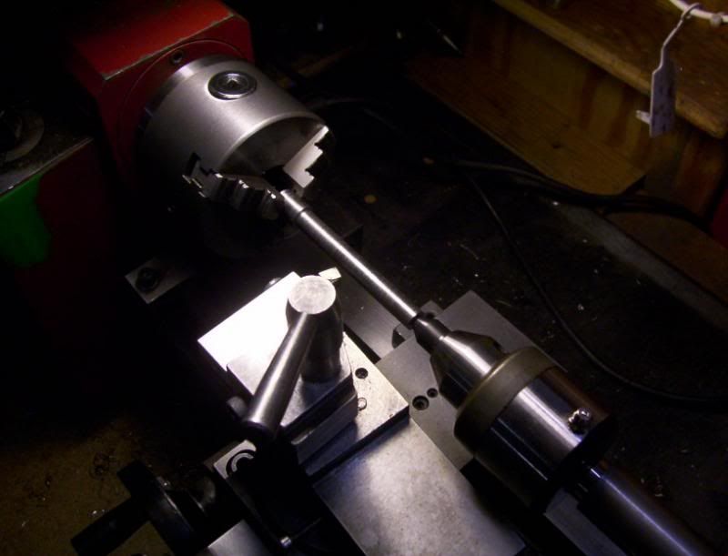
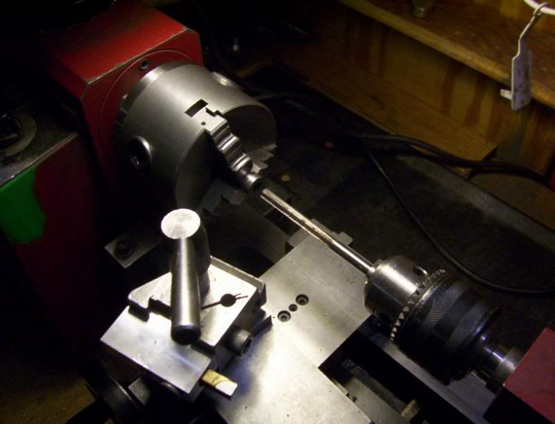
now back to the lathe to center drill for a tailstock live center support
so I can machine down the dia. to form the cap for the housing.
when I cut the caps off thees housings, I want to make sure they go back on in the right order, so using my number punches I marked each housing side with its appropriat cap that will later be cut away.
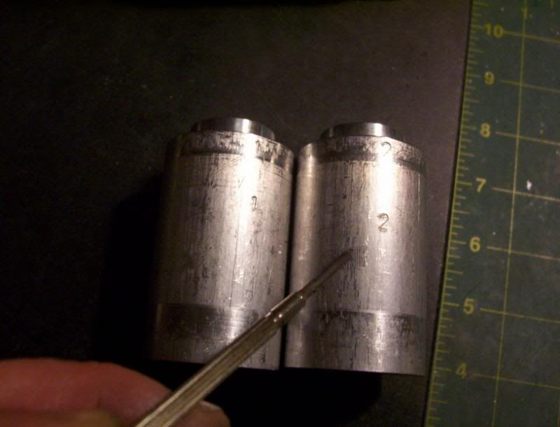
they housings to thios point ready to have there caps cutaway.
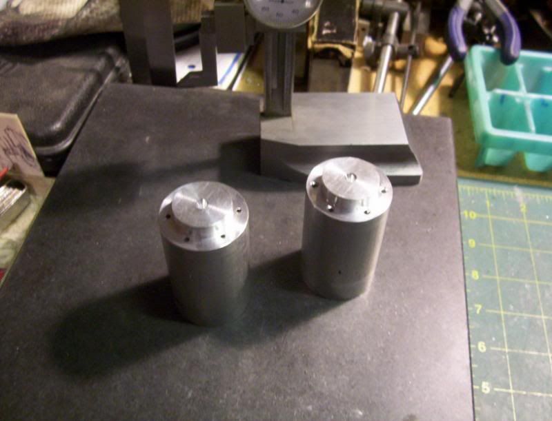
now marking off the thickness of the caps, for the housings.

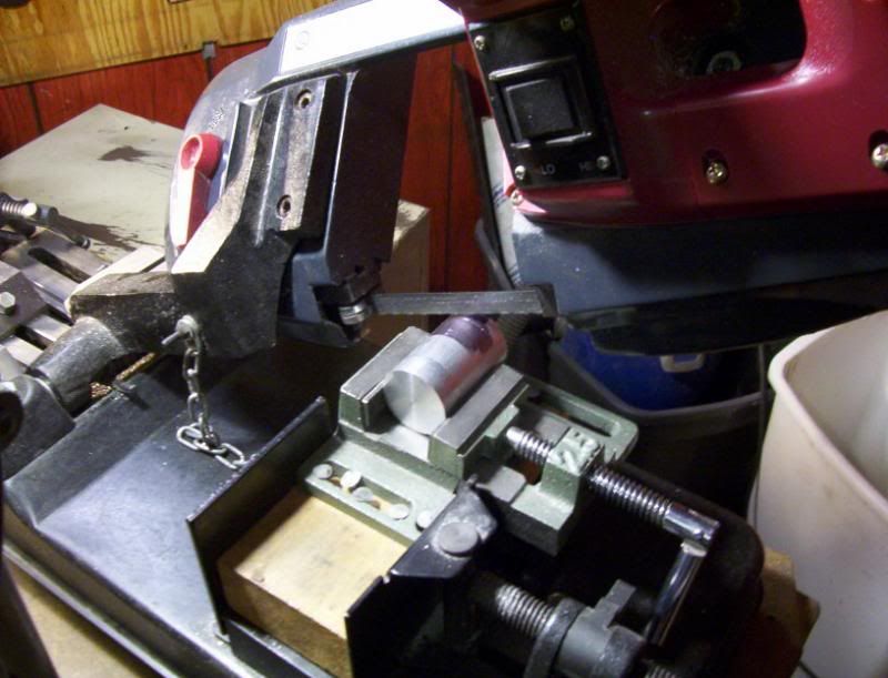
And my wonderful benchtop bandsaw, this machine ranks up there with my mill and lathe for accuracy, in cutting to a line. If I have real heavy rough stock to cut to rough length, I use my 4x6 vert/hor. bandsaw in my shop outside shed, but when I need a accurate cut where very little machining on the mill is needed I turn to this saw to get the job done.
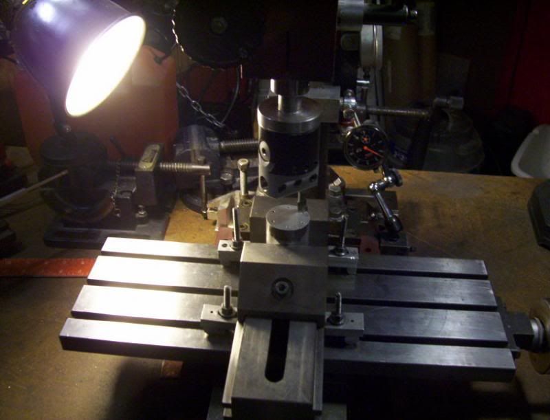
I have discovered how well flycutters work when you sharpen them, so I use flycutters alot in my mill, but this time my flycutter set is to small for this workpiece, so I tried using my boring head and it worked perfectly.

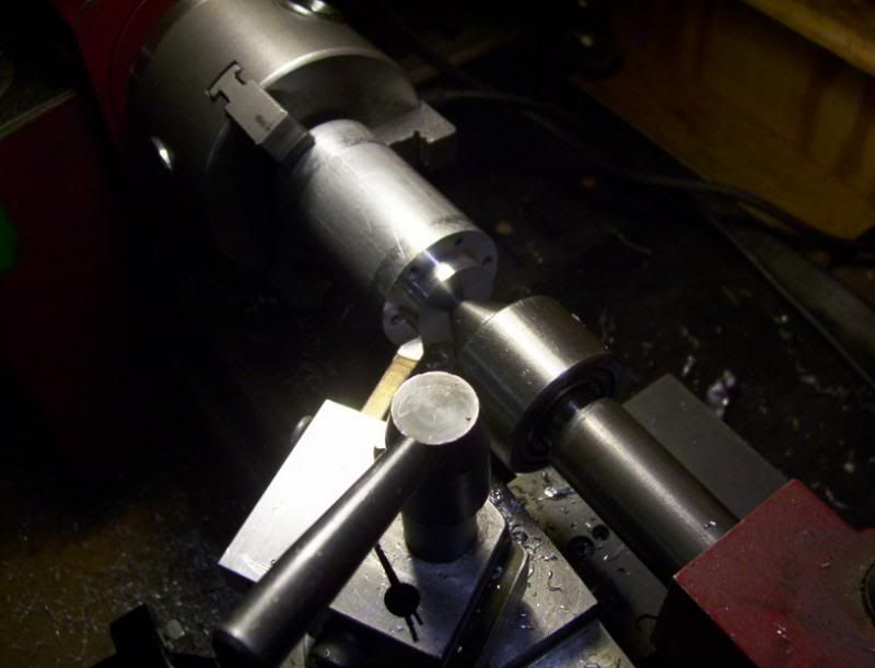
ok the caps are cutaway, again this is so I can drill and ream thru holes for the cylinders sleeves, then cap off the housing to close up the piston cylinder sleeve.
It's time to drill and tap the holes in the housing body to be able to attach and screw down the caps.
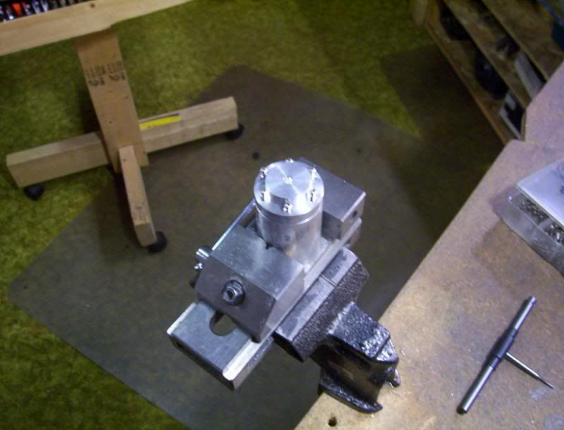
and a trial fit of the housing cap screwed together with its body.
I do want the valve cylinder sleeve to protrude the housing cap, so with everything screwed in place tight, I begin to drill and ream for the valve sleeve hole.


Now after all that is done, with the valve sleeve hole, with the cap off I can start drilling and reaming the piston sleeve hole, remember the valve hole was drilled through the cap, but this piston sleeve hole is drill with the cap off, so the cap can cover up the piston hole during final assembly.

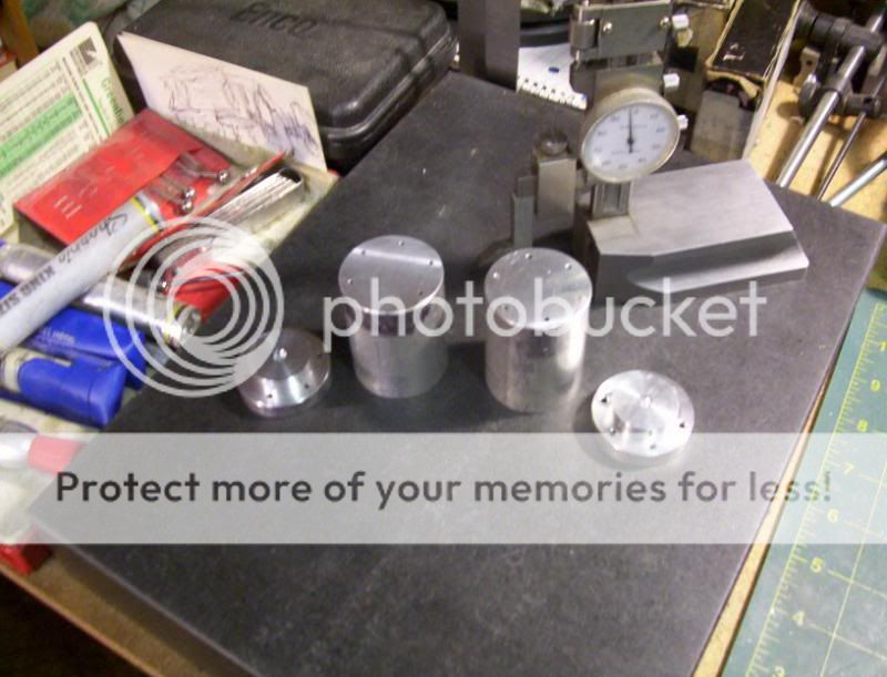
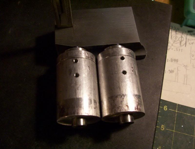
here are both housings done with the sleeve holes drilled and reamed to final size,
the one on the left, is the top side of the housing when fitted to the vee block, the one on the right is the bottom side, facing the crankshaft.

ok with all this talk about sleeves, its time to start making them, here is one of the valve cylinder sleeves being machined to outside dia, producing a flange.
now the inside dia. drilled and being reamed to final inside dia.
the best way to make this sleeve permanently stay in the sleeve housing, is with zap a gap super glue, this works excellent for my applications.

here is a blurry pic, of the housings top and bottom with there valve cyl. sleeves glued in.

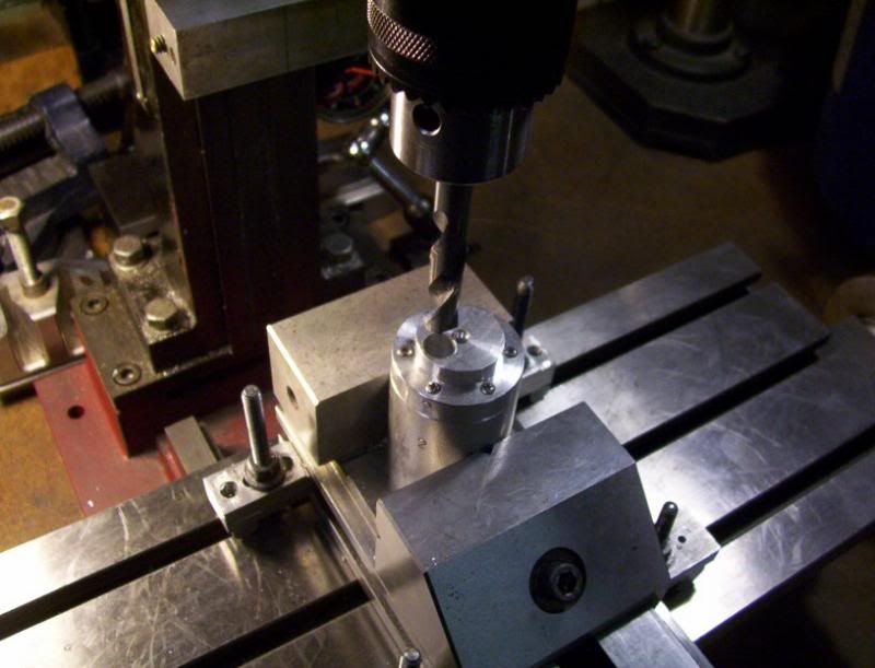
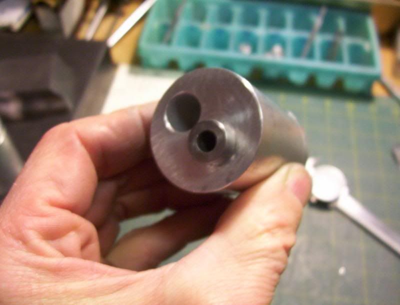
Ok now before I work on the piston sleeves, I want to drill the valve holes for the intake and exhaust, wich will now pass through the valve cyl. sleeve, and into the bored out hole for the piston sleeve. The reason I can do this, is because the piston sleeve will be cut short in length so these holes will not be covered up by the piston sleeve, when I later insert it in to this hole.
So now some carefull lining up the valve bore with the piston bore,

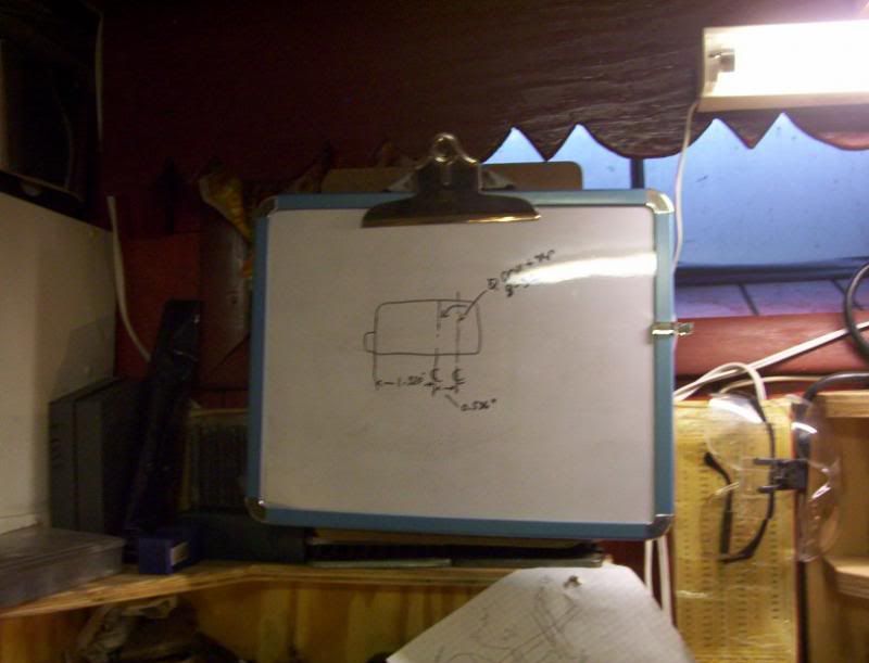
my 'mad' (manual aided drafting), of this part to be machined,
and the drilling of the valve intake and exhaust holes commences.
I'm tapping 8-32 thd. these holes for later fittings so both housings can be connected through some sort of a intake and exhaust manifolds system.

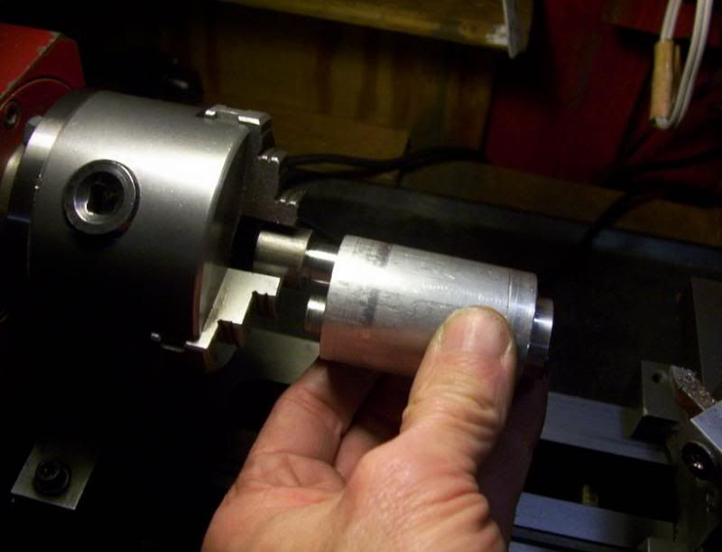
Now I can start machining the piston cyl. sleeves, first the ouside dia. to make a flange.

and a test fit with its housing
and thats all for now.
since this is a project for weekends it will take some time, I'm not going to rush it, but do a little at a time, so the next post may be some time next week.
Have fun in the shop...


my very first engine I ever built, and designed from scratch, was a double acting valve system, with scotch yoke connection for the valve.
When I apply air to it, it revs up very fast, and when I shutoff the
air intake, for a brief moment, the flywheel momentum goes rather strongly, so as air intake is applied and relieved, it gives a sound of an engine reving up, plus the air exhaust gives that puffing sound, so combining all that, I can make the engine sound like its reving up.
Now I just built a very quick one valving engine, with no spring tension for the valve system, but rather the classic eccentric/strap combination, this has a positive movement on the valve, both forward and backward in its cylinder, so with no spring tension, it has the ability to rev up and rev down with flywheel momentum, without stopping abruptly.
Here is that engine, I also built it as an experiment to see how painting my projects would work for me.

Now as I was playing around with my engines of late, I thought about building this same engine, since now I have all the location dimensions figured out for the valve holes, as well as the valve length, where it is machined at for the valving, the piston con rod length, and a few other major dimensions, already in working order, so with all this already established, I decided I want to build this type of engine again, only make it a twin cylinder vee design.
So here is the start of this engine build:
since this is designed to have both the piston cylinder sleeve and the valve cylinder sleeve, in the same round block, I needed to use my 1-1/2" round bar I have on hand.
This dictated the whole design of my engine shown above, If I had something of different size, the design would have gone that dirtection instead.
Because I am using a bar stock bigger than my 7x10 mini lathe steady rest could handle, I have to use my shop made steady rest to handle stock up to 2" in dia.
here is one of the cylinders housing being faced off to length, in the steady rest.

once they are machined to length, I need to drill 6 holes at 60 deg. on my rotary table, around the perimeter, these holes will be tapped to 2-56 thread.
So after some elaborate clamping to the vee blocks, I then proceeded to tram in the round workpiece to center of the rotary table.

now all the holes were drilled at 60deg. increments, these holes were drilled a certain depth for tapping, then finished off with a body drill for a 2-56 screw to a certain depth for the screw to pass through part way. The reason for this is because I am going to cut this section away to be screwed back on as a cap, and the reason for that, is, because it is easier to drill and ream a through hole for the valve and piston cylinder sleeves to fit into, then to drill a blind hole.
The valve cylinder sleeve will go all the way through, but the piston cylinder sleeve needs to be capped off after the hole has been drilled and reamed all the way through.

now back to the lathe to center drill for a tailstock live center support

so I can machine down the dia. to form the cap for the housing.


when I cut the caps off thees housings, I want to make sure they go back on in the right order, so using my number punches I marked each housing side with its appropriat cap that will later be cut away.

they housings to thios point ready to have there caps cutaway.

now marking off the thickness of the caps, for the housings.

And my wonderful benchtop bandsaw, this machine ranks up there with my mill and lathe for accuracy, in cutting to a line. If I have real heavy rough stock to cut to rough length, I use my 4x6 vert/hor. bandsaw in my shop outside shed, but when I need a accurate cut where very little machining on the mill is needed I turn to this saw to get the job done.

I have discovered how well flycutters work when you sharpen them, so I use flycutters alot in my mill, but this time my flycutter set is to small for this workpiece, so I tried using my boring head and it worked perfectly.


ok the caps are cutaway, again this is so I can drill and ream thru holes for the cylinders sleeves, then cap off the housing to close up the piston cylinder sleeve.

It's time to drill and tap the holes in the housing body to be able to attach and screw down the caps.


and a trial fit of the housing cap screwed together with its body.

I do want the valve cylinder sleeve to protrude the housing cap, so with everything screwed in place tight, I begin to drill and ream for the valve sleeve hole.


Now after all that is done, with the valve sleeve hole, with the cap off I can start drilling and reaming the piston sleeve hole, remember the valve hole was drilled through the cap, but this piston sleeve hole is drill with the cap off, so the cap can cover up the piston hole during final assembly.


here are both housings done with the sleeve holes drilled and reamed to final size,
the one on the left, is the top side of the housing when fitted to the vee block, the one on the right is the bottom side, facing the crankshaft.

ok with all this talk about sleeves, its time to start making them, here is one of the valve cylinder sleeves being machined to outside dia, producing a flange.

now the inside dia. drilled and being reamed to final inside dia.

the best way to make this sleeve permanently stay in the sleeve housing, is with zap a gap super glue, this works excellent for my applications.


here is a blurry pic, of the housings top and bottom with there valve cyl. sleeves glued in.

Ok now before I work on the piston sleeves, I want to drill the valve holes for the intake and exhaust, wich will now pass through the valve cyl. sleeve, and into the bored out hole for the piston sleeve. The reason I can do this, is because the piston sleeve will be cut short in length so these holes will not be covered up by the piston sleeve, when I later insert it in to this hole.
So now some carefull lining up the valve bore with the piston bore,

my 'mad' (manual aided drafting), of this part to be machined,

and the drilling of the valve intake and exhaust holes commences.

I'm tapping 8-32 thd. these holes for later fittings so both housings can be connected through some sort of a intake and exhaust manifolds system.


Now I can start machining the piston cyl. sleeves, first the ouside dia. to make a flange.

and a test fit with its housing

and thats all for now.
since this is a project for weekends it will take some time, I'm not going to rush it, but do a little at a time, so the next post may be some time next week.
Have fun in the shop...


