Philip Duclos "Odds N Ends" hit and miss engine

Home Model Engine Machinist Forum

Help Support Home Model Engine Machinist Forum:

This site may earn a commission from merchant affiliate links, including eBay, Amazon, and others.
Great job Brian. Thanks so much for the pics and the explaining how you done things. I cant wait to see it run. Bill
 
Nice work Brian.. How about a Video of trying to get it to start the first time?
 
The plans call for a .013 dia. music wire spring with 12 coils and an inside diameter of 1/4"+ for the intake valve. I took a chance on an "off the shelf" spring from the hardware store that was .020 dia. wire, but its too stiff. If the spring is too stiff, the vacuum created when the piston moves down on the intake stroke won't be enough to overcome the spring tension, and the atmospheric intake valve won't open. I have a piece of .015 music wire I picked up yesterday at the local hobby shop (the smallest they had), so I am about to wind a spring from it. If it is still too heavy, I will visit a music store tomorrow and buy a guitar string of .013" diameter. As much as I want to rush ahead and try to start this engine, I have learned through my previous 3 i.c. builds that this stuff has to all be looked after BEFORE I try and start the engine.
 
Not trying to get in your business Brian but there is a good information in the link below. If the wire you bought dont work maybe some of this will help. Keep scrolling to the bottom of the pages till you get to the page on tuning springs or tweaking them it says i think. My fingers are crossed for you..Bill

http://home.earthlink.net/~bazillion/intro.html
 
Thanks Bill--Springwinding is pretty straightforeward stuff once you've been shown how. A man called "Deanofid" did an excellent tutorial on this forum a few years ago. There is an element of guesswork in "freewinding" onto a mandrel. I needed a spring just slightly bigger than 1/4" inside dia. so I wound it on a 1/4" mandrel. When the pressure was released, it sprang to 3/8" inside. So---I wound another on a 1/8" mandrel. When released, it jumped to 3/16" inside. So---then I wound it on a 3/16" mandrel, and it ended up perfect, about 17/64" inside. I won't heat treat this spring, it will be fine for its purpose without heat treat. If it eventually loses its compressibility, I will wind another and heat treat it.
 
A friend has recently recommended stainless steel fishing tackle trace which seems to come in the right sizes. I have not tried this yet but he reckons it works so I intend to use it for valve springs in the next week or so.

Jim
 
You can take some of the guess work out of springs if you look in MACHINERY HANDBOOK. There is a table with mandrel diameters and wire diameters that tell you what size to use to get a specific ID. In my experience its pretty accurate. I wont offer a page number because it will depend on your edition.
 
People are asking for a blow by blow description of the initial start up of this engine. Are you MAD!!!! The next few days will be a lot of things. It will be a confusion of cobbled up electrical wires---No need for them to be made neat and pretty untill the engine actually runs. It will be a time of "borrowed parts " from other engines---i.e. the gas tank off my Webster--again, no need to build a pretty dedicated gas tank if the engine never runs. The counterweights are wrapped with swaths of masking tape to keep them from operating. I don't have time to fool around with the intricacies of hit and miss mechanisms untill I see if the damned engine will fire in normal mode. I have a can of quick start ether. I have a fire extinguisher mounted on the wall beside me. I have warned my good wife to not be alarmed at the sound of explosions or curses drifting up the stairwell from the basement, but to be prepared to call 911 if everything goes totally cock-a-hoop. These are the times that turn lap dogs into ravening monsters, and put good Christian boys like myself in danger of their mortal soul.---And people want to see this in living colour with video as it happens!!! Here is my best offer---This is all the pics you get of the "just before" sequence. From here on we go into "black out" untill we have an operating engine. If you never hear from me again, you will know the engine never actually ran, and that I have taken up pole dancing as a hobby.----Brian
INITIALSTARTUP001_zps64ecdaf4.jpg

INITIALSTARTUP003_zps20c2e24d.jpg

INITIALSTARTUP002_zps2dad2c33.jpg
 
I'm getting excited Brian:D 
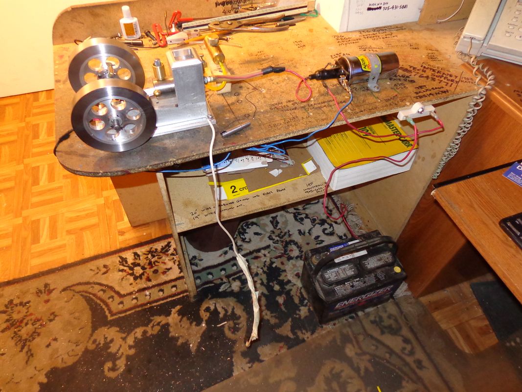
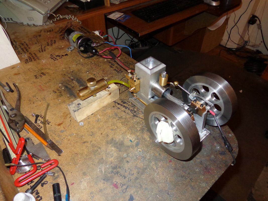
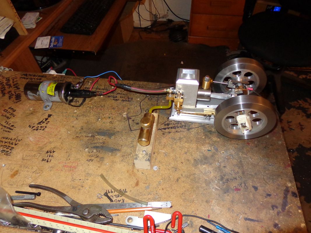
Just one question, do you have an earth wire from your engine frame to the coil mount/case? Can't see it in the pictures:eek:
Have Fun
Terry
 
Terry---It doesn't need one. Electricity flows from the battery positive post to the + side of the coil. Then from the - side of the coil to the points, then through the points to the engine block. A wire runs from the engine block to the negative post on the battery. Thats all it takes to complete the primary circuit. When the points open and the primary field collapses, that "excites" the secondary coil for the 20,000 volt spark that follows out the spark plug wire to the plug, jumps the spark gap to the portion of sparkplug that is screwed in to the engine block, then follows the same wire back to the negative side of the battery as the primary circuit uses. I've got lots of good spark. I did go down town this morning and buy a condenser to wire into the points. When the primary field collapses as the points open, the collapse also "excites" a current flow in the primary windings that will backflow through the points, causing them to arc and burn out quickly if they don't have a condenser wired in. My problems this morning are the same problems I've had with every i.c. engine I have built--Low, poor compression. I have already had the valve bodies apart and relapped the valves, then reassembled with new gaskets and permatex gasket cement, but its leaking compression thru the exhaust valve. I'm about to quit for the day now, as I can only handle so much frustration at one setting.---Brian .
 
but its leaking compression thru the exhaust valve. I'm about to quit for the day now, as I can only handle so much frustration at one setting

Good work Brian.
is I can give you a little trick to prevent you from taking your head appart.
Clean your valves and seats
mark your valve seat with a lead pencil and then turn them with your finger in their seats, a few turn will do
If you look at your valve seat and valve face you should have a nice small dark line all the way around wher your valve is
matting your seat.
when you see this you can bet that they are not leaking

good luck
 
Still here and looking forward to the noisy bit.

Thank you so much for the thread. I am a bit sad now that it is coming to an end.

But I am sure there will be more.

Jim
 
Luc---See posts 149 and 150.

Yes I've seen those but them thickness of that blu stuff is about
100 time more then pencil lead

If your willing to go more precise then lead

use "suit" or carbon not sure how you call it. you know the black smoke
from an oil lamp or a lighter and your line will be about 10 to 20 thou
wide max

cheers
 
Okay Luc--I will give the lead pencil or soot a try. With a bit of CAD magic, you can see a cross section taken through the exhaust valve body and the exhaust valve. The threaded outlet on the left side is where the muffler screws into. The hole in the right side is the port which leads into the cylinder. The big hole up top is plugged by the intake valve assembly when its all put together. I believe (and this is only conjecture at this point) that the seat area is too close to the port into the cylinder. I THINK this causes some distortion of the seat area which causes the leak. The head of the valve is .375" diameter. The stem is .125" diameter. The hole that the head of the valve sets in is .437" diameter, cut with a .437 endmill to achieve the flat bottom. The 45 degree seat is cut with a manual seating tool which is guided by a "nose" that fits into the valve guide, to ensure concentricity. The exhaust valve body is a complex part, which I seriously do not want to make over again. I think the valve is fine too. I think there is enough room between the seat and the outlet to the muffler, that I can set this part up in the mill, line it up with a 7/16" dowel in the mill chuck to be perfectly concentric, and shove that .437 counterbore down another .030". That will get rid of the existing seat, leaving me an area in which I can recut a new seat. The valve will set a bit lower in the housing, but there is lots of adjustment in the rocker arm to accomodate that.
EXHAUSTVALVEBODYWITHVALVE_zps16ac6130.jpg
 
Last edited:
Brian
are you cutting your seat at 44 degree and valve at 45 this will put your matting surface right in the middle
Hope it's help you
cheers
 
Brian
are you cutting your seat at 44 degree and valve at 45 this will put your matting surface right in the middle
Hope it's help you
cheers
Well actually Luc--I cut the seat at 45 degrees because thats the angle at which I made my manual valve seat cutter, and cut the valve at 46 degrees because I can manually adjust my lathe compound to whatever angle I want.
 

Latest posts

Back
Top