Hi Everyone
Here are some construction photos of the Pacific rod; the rod has brasses on each end with a turned steel center. I wonder if this is a hold out from the steam engine designs; the split small end bearing isnt something you see very often on an IC engine.
I accidently deleted the construction of the brasses and didnt take any of the hardware machining. The brasses were left a little oversize on the radius so they could be turned as a unit assembled on the rod. I roughed them out on the CNC so that is how I originally generated the radius.
First a suitable piece of 12L14 stock was faced to length and centered on both ends.
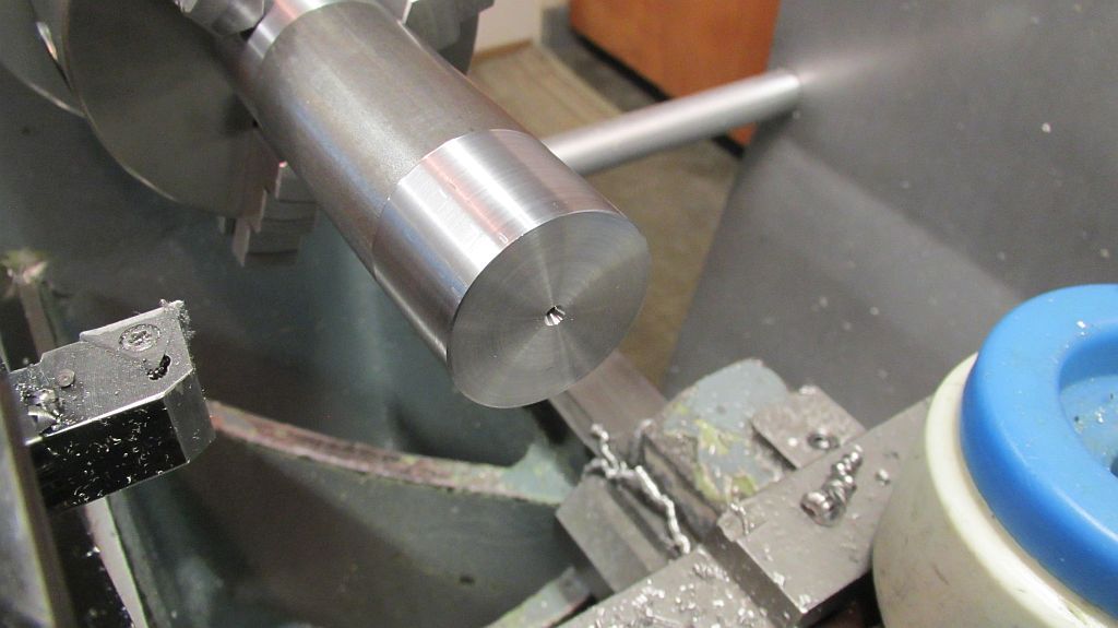
Then the center was machined just a little larger than the finished fat part in the middle of the rod.
Using a V block the profile on each end of the rod was machined leaving the radius on the ends a few thou over for turning later; also at this time the holes were drilled.
Here the 1/16 hole is drilled all the way to the middle of the rod for oiling; it gets an intersecting hole put in later.
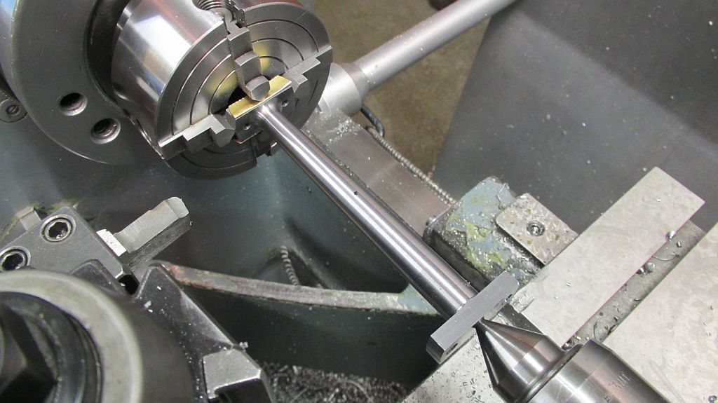
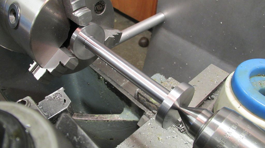
Back in the lathe and indicated in using a 4 jaw chuck the first taper is machined and the radius at the root is also cut with the same tool.
You may notice that in the next few pictures the radius at the root is smaller; that is because I goofed and made it too large the first time. I re-ground the tool and went back and re-cut them.
Not shown the rod is flipped and the same was done for the other end.
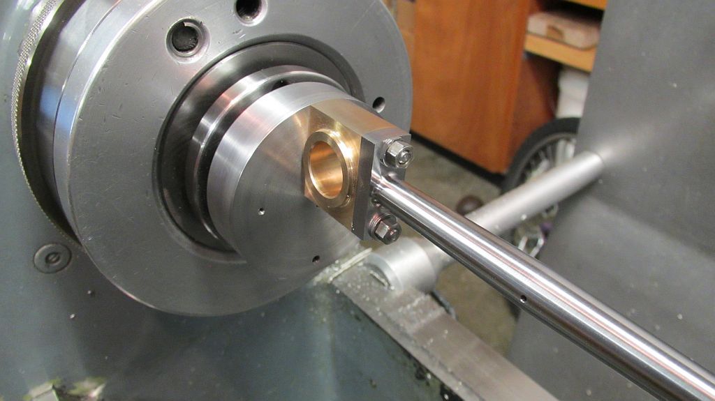
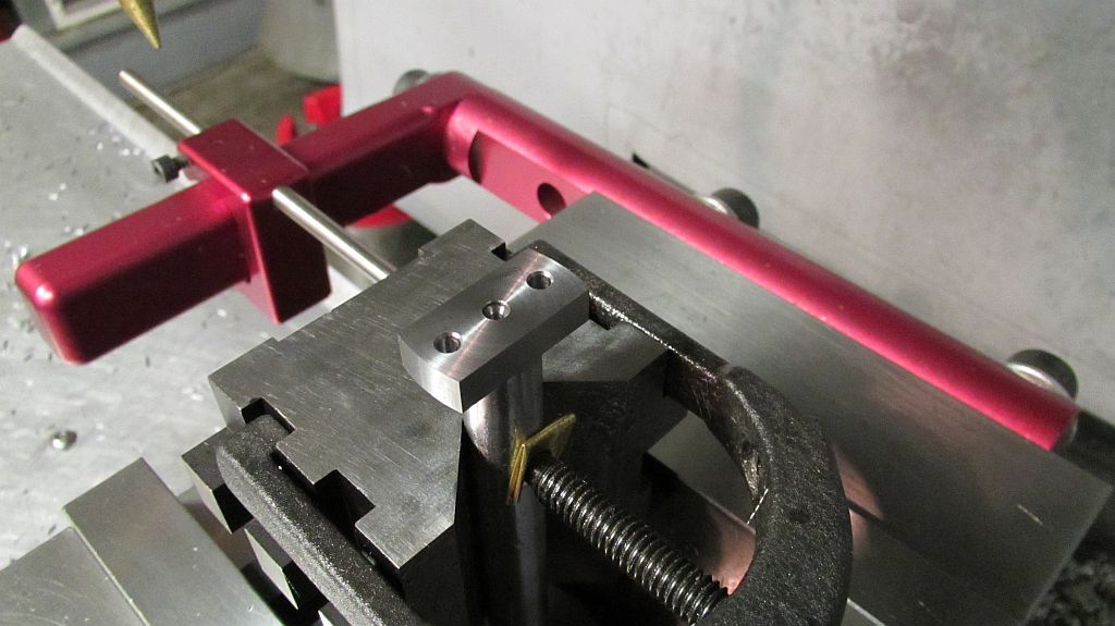
Turning the radius on the sides was a bit of a challenge; the radius is not centered with the rod axis so the rod assembly needed to be offset for turning.
A fixture was made the mount the rod assembly to with the proper offset; two sets of mounting holes were included. One set for each end of the rod.
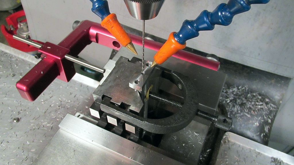
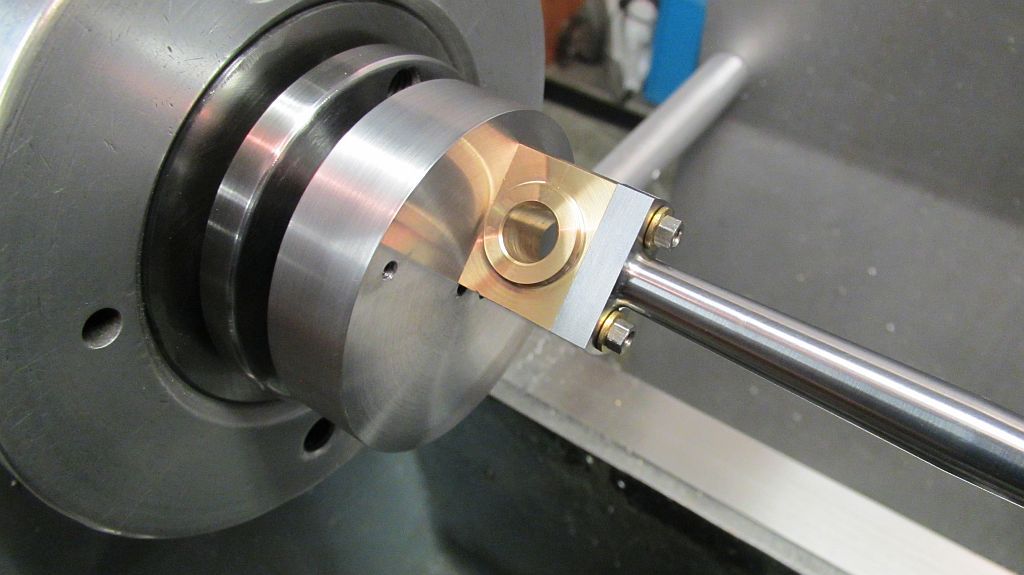
First the big end is done; first one side the rod is removed and rotated and then the other side is turned. Two pair of special stepped studs were made as the one end of each of the brasses is threaded so a thread size that would slide through the threaded hole was chosen.
First the big end is done; first one side the rod is removed and rotated and then the other side is turned. Two pair of special stepped studs were made as the one end of each of the brasses is threaded so a thread size that would slide through the threaded hole was chosen.
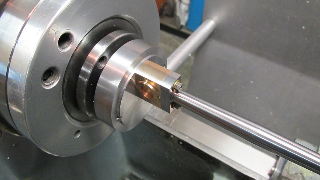
And after the first side is completed; you can see part of the fixture was machined away so the tool would clear the end of the bearing.
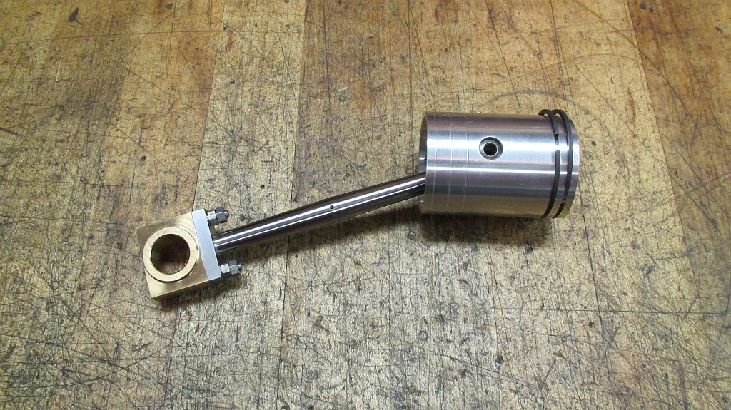
The completed piston and rod assembly with the proper hardware
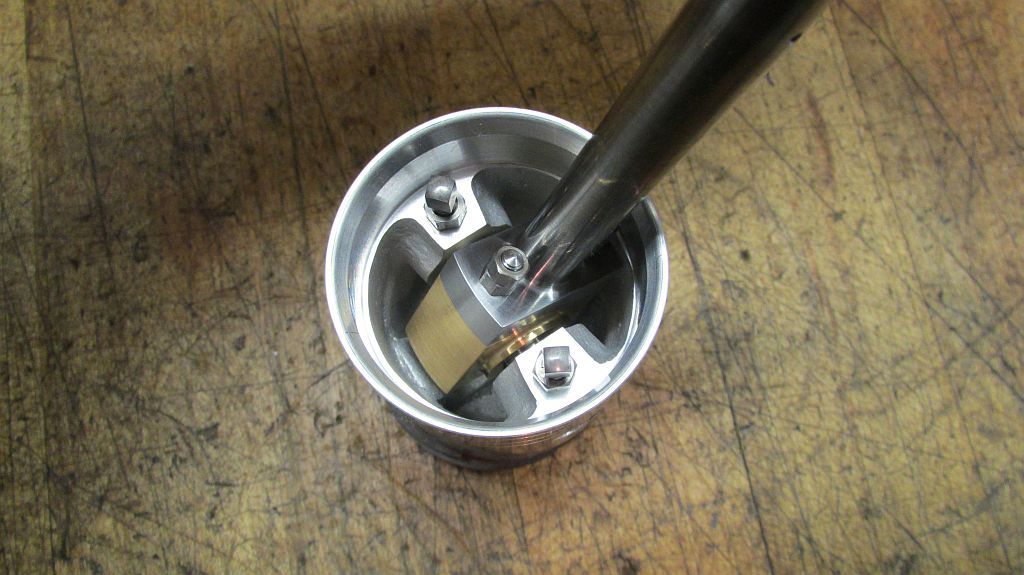
Here is a shot of the inside.
I need to do a thorough cleaning of the cylinder then I can do a test fit of the new parts.
Thanks for checking in,
Dave
")


