Pacific Vapor Engine from Morrison & Marvin Castings

Home Model Engine Machinist Forum

Help Support Home Model Engine Machinist Forum:

This site may earn a commission from merchant affiliate links, including eBay, Amazon, and others.
Hi Everyone

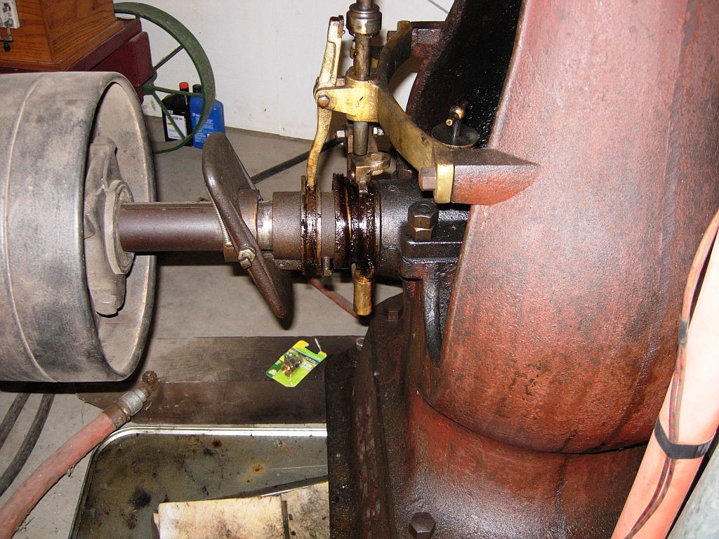
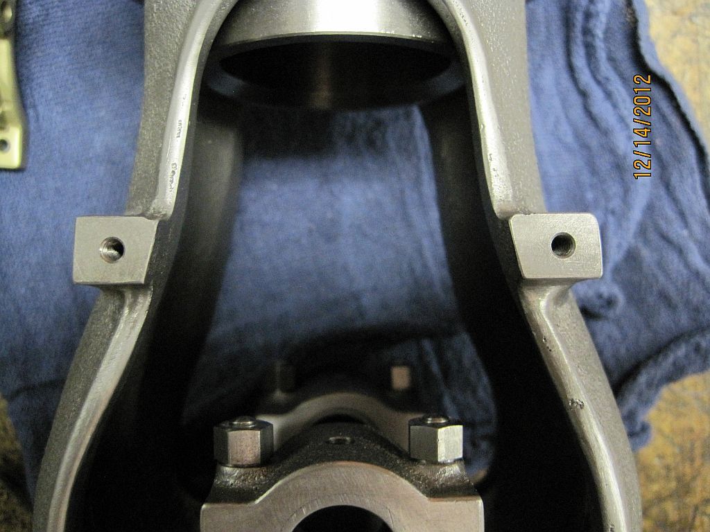
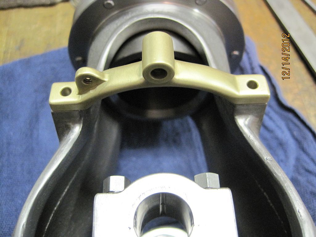
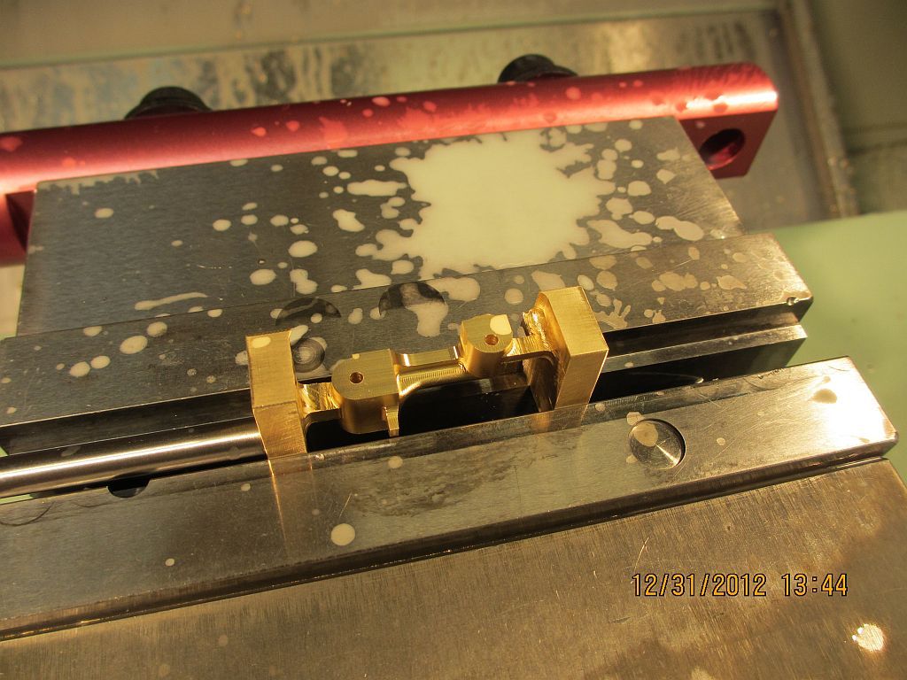
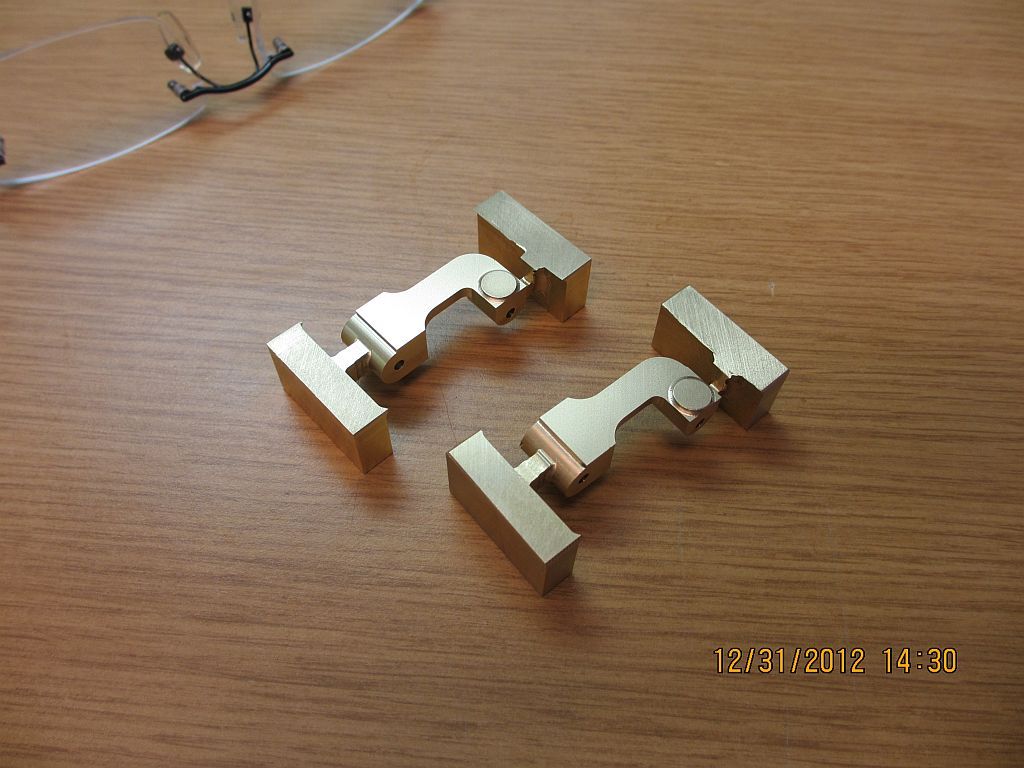
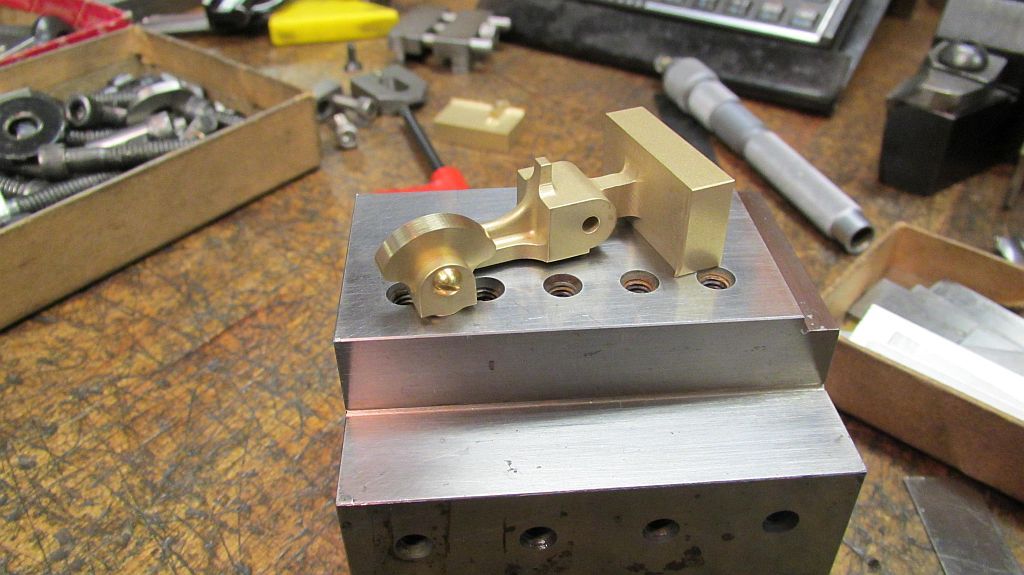
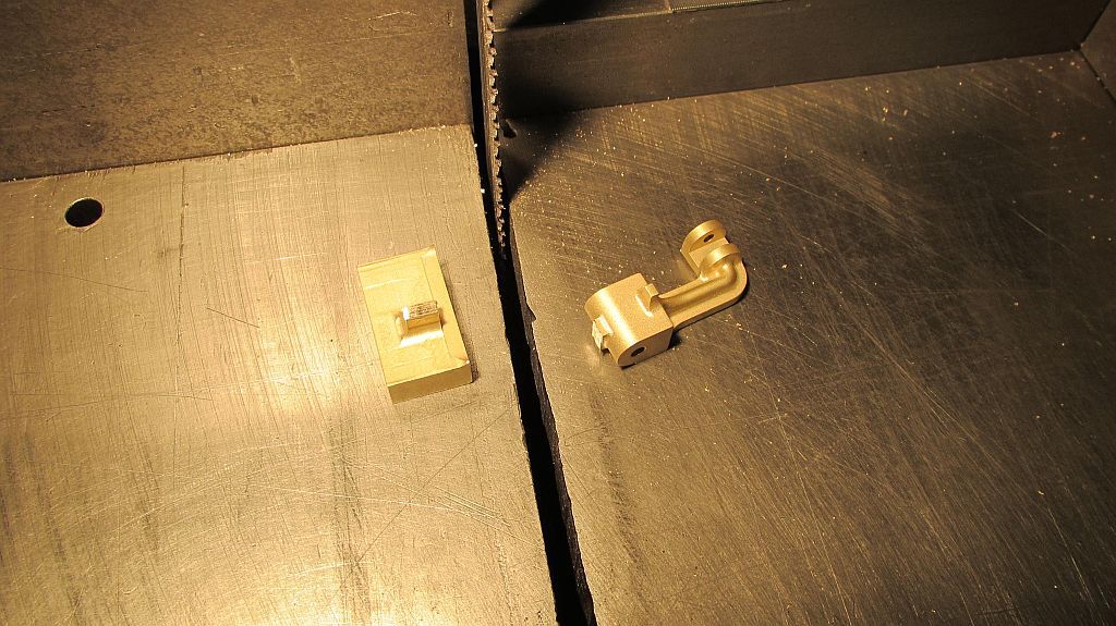
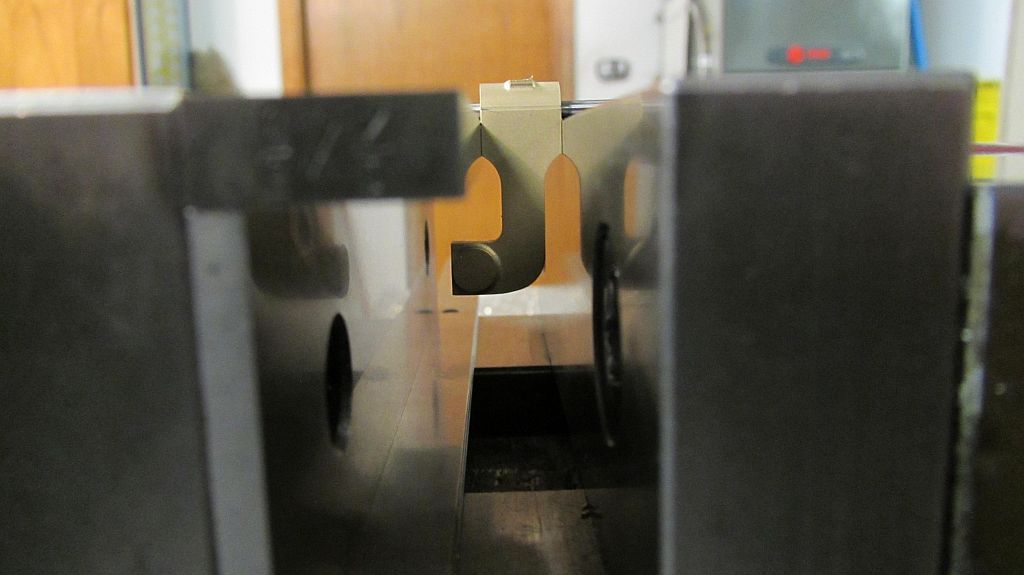
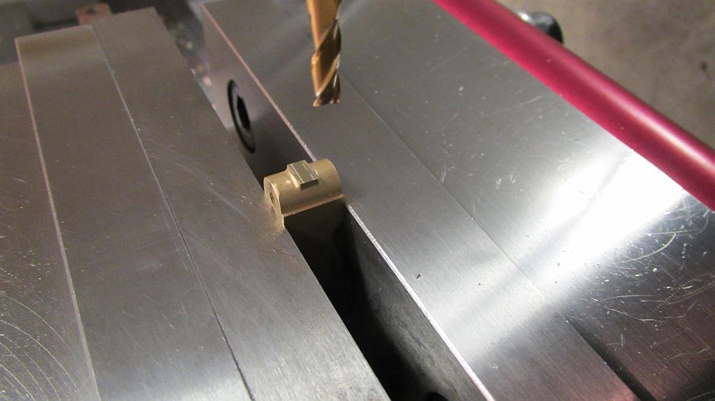
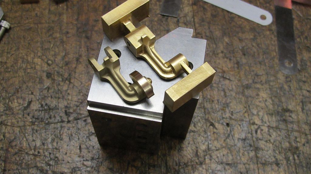
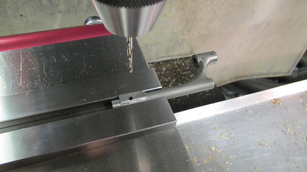
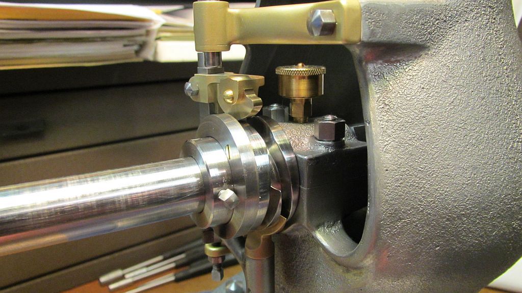
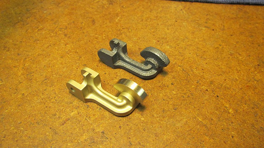
I wanted to post a picture of a large Pacific that currently lives at Antique Powerland near Brooks Oregon. This is the engine that caused me fabricate the brass upper swing arm bracket and soon to follow brass valve lifter assembly. This is a large engine (I'm not sure of the horse power but it stands well over 6ft. Tall) so some of the proportions are different than the model.

Buzz_001.jpg

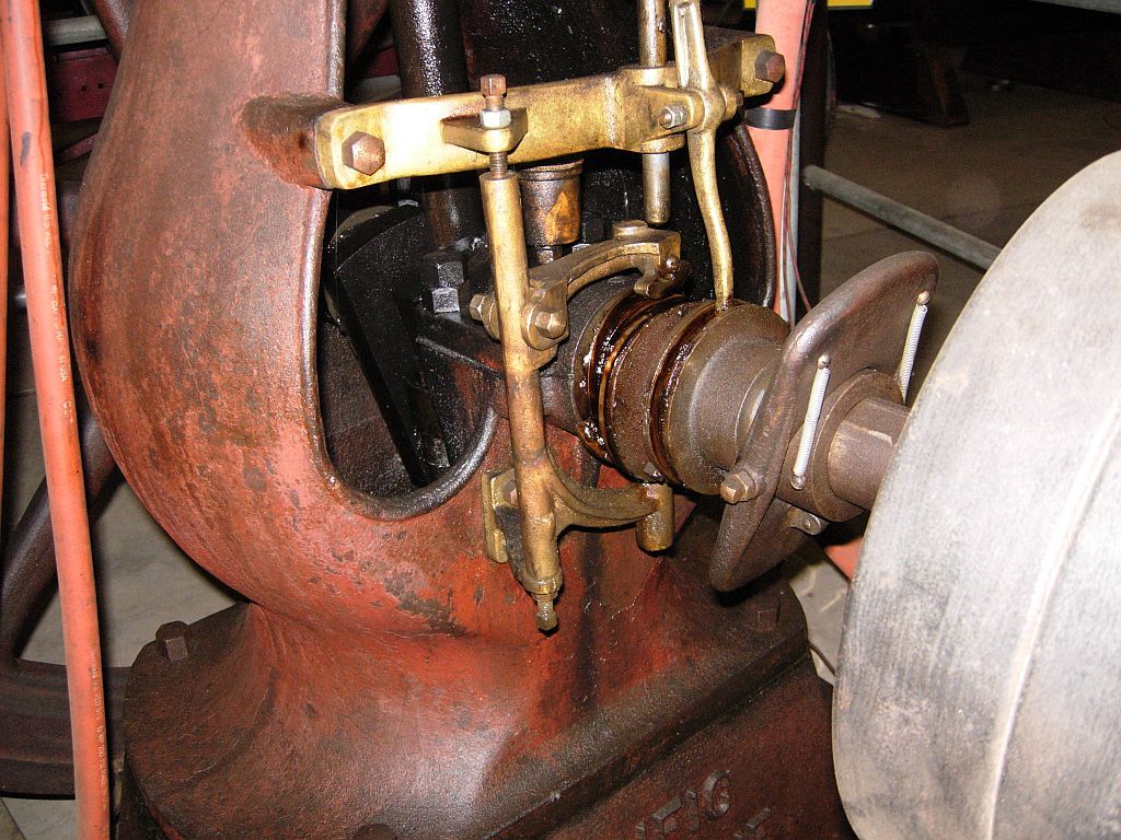
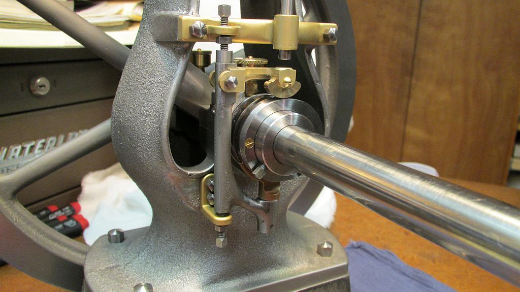
This engine also has the hit & miss dog bone governor.

As I think I may have indicated before; at this time I'm not planning on using the governor on my engine because it occupies space on the crankshaft that I have other plans for.

Thanks for checking in,
Dave
 
Not seen that type of governor before, I assume that as the speed increases it straightens up and pulls the spool out to work the lever.

J
 
You are correct Jason: there is a link at the bottom of the weight that is connected to the spool which operates the latch arm.

Buzz_002.jpg

Here is another view.

Dave
 
Hi everyone,

I have been tidying up a few loose ends on the bottom end with regards to the timing parts.

You may have noticed in that last few pictures of my engine that the main bearing area had some pretty sharp corners. This was because I needed to remove some material from the casting to shift the crossover cam closer to the center line of the engine. I spend a good part of the morning filling and blending in this area.

The crossover cam was also substantially trimmed to get things to come out to my liking. I will go over that later. Hopefully with in the next couple of days.

One other thing I didn't cover was when I had the body set up in the mill to fit the upper swing arm bracket; I took a cut across the bottom surface of the bosses as there was quit a bit of extra material in this area. This required some filling and blending to match the machined surfaces with the casting.


UpperBracket_001.jpg

Here is the body after some hand work; notice the top and bottom surfaces on the bosses are now parallel.

UpperBracket_002-1.jpg

This picture shows the fit of the upper swing arm bracket on the bosses.

Going back to last summer the lift cam was machined last summer; I made a couple of extras one for my friend who is working on his Pacific and one more just in-case.

Cam_001.jpg

Staring out the stock is faced.

Cam_002.jpg

Then Drilled.

Cam_003.jpg

And bored to size.

Cam_004.jpg

Then set up in the mill in a V block and indicated in.

Cam_005.jpg

Both directions.

Cam_006.jpg

The mounting holes are spotted and drilled.

Cam_007.jpg

Then the profile machined.

Cam_008.jpg

Ready to go back in the lathe.

Cam_009.jpg

The Cams are parted off to the proper length

Cam_010.jpg

Here are the finished cams.

Thanks for checking in.

Dave
 
Dave, beautiful work as usual and the pictures, studio quality.

I have a couple of questions if you have time.

First, the finish on the parts as they come out of the machine is perfect. Do you use carbide and insert tooling for the most part?

Second, the indicator shown is mounted directly in the mill chuck. Is it made just for that? Mine has dovetails on the back and top and I can't put it directly in the chuck, I have to use a holder. What brand is it?
I can't quite read the name on the face.

GUS
 
Thanks Gus,

I use (when ever I can) positive geometry insert tooling. The ones I use quite often are TCGX inserts from Sandvik; some years back I was able to put together a pretty good stockpile from eBay. These inserts are fragile due to their high rake and very sharp edges; but used with care they work great on most free machining metals and plastics.

We just bought some Kennemetal holders and inserts at work to use on the Hardinge HLVs. I could look them up if you are interested; they are available form MSC but inexpensive.

The indicator is an Swiss made Interapid; these are in my book one of the finest test indicators ever made.

If you are in the market for one check on Long Island Indicator web site as they have a lot of good information. When buying a used one say off of eBay there are some earlier models to stay away from because they are not repairable. http://longislandindicator.com/p23.html

Oh and to answer you question the shank is integral to the indicator; it is on a friction pivot so it is easy to position.

Best regards,
Dave
 
Hi everyone

Today I got the cap for the exhaust valve machined; not a major accomplishment but one more little piece. I deviated somewhat from the plans (do we see a pattern here?). I have seen some photos of a Pacific engine (maybe it was a Union or Regan as there all related) that had a pleasing dome shape on the top as well as the outer rim of the flange having a nice radius. The flange also overhung the boss on the valve chest slightly. So this is how I decide to make mine.

ValveCap_001.jpg

Starting with a piece of 660 bearing bronze (I like the color) it was faced and turned.

ValveCap_002.jpg

Then single point threaded 9/16"-18 to match the valve chest.

ValveCap_003.jpg

The radius on the rim was hand filed, sanded and polished.

ValveCap_004.jpg

Flipped around the stock brought to length.
I had calculated all the points in my CAD program and a step over and cut approach was used to form the dome.
Here you can see the small lines that need to be sanded out to fully define the shape.

ValveCap_005.jpg

Here it is after some blending ready to cut the hex.

ValveCap_006.jpg

Set up in the mill and indicated in.

ValveCap_007.jpg

The hex is cut.

ValveCap_008.jpg

And returned to the lathe to put the 15 deg. bevel on the hex.

ValveCap_009.jpg

Here it is installed on the valve chest; now I need to make the copper sealing washer to go under it.

Thanks for checking in,
Dave
 
Hi Everyone

Thanks Pat; I'm pleased with how that little cap turned out; there is a surprising amount of work in it.

I managed to get get a little more accomplished yesterday. I countersunk the mounting holes in the lift cam which as far as I know is how the original was mounted to the crossover cam. I also got the square head set screws machined and casehardened.

The crossover cam was made by Samuel Park at Imperium Tool and Instrument in Bute MT. He has these cams available for Pacific builders. That is unless you have a 4th axis on your CNC or want to design and fab an ingenious machining fixture as Lester did for his engine.

These cams are a nice piece of work, reasonably priced, and the crossover motion is very smooth.

CrossOverCam_001.jpg

Here is the cam as received; note the extra material on the inside end which can be machined away to adjust the position of the cam on the crank.

CrossOverCam_002.jpg

Here is the cam after removing the proper amount of material for my engine and valve lifter arrangement.

CrossOverCam_003.jpg

As I had indicated before I removed quite a bit of material from the cam and the main bearing housing as well.
This is because I want to have the lift arm more inline with the lift cam (personal preference here); also I will be machining my lift arm from brass stock instead of using the supplied iron casting.

If you look at the pictures of the original engine you can see kind of how the lift arm will look. The one for the model will be slightly different as the model is scaled from a smaller engine.

CrossOverCam_004.jpg

Checking the fit on the engine; notice the lift cam has been installed with the proper flat head screws and the square head set screws to secure the crossover cam to the crankshaft.

CrossOverCam_005.jpg

Here is a side view showing the engagement of the follower shoe and swing arm.

CrossOverCam_006.jpg

And a view from the back side.

Next I will probably tackle the lift arm and bronze shoe that runs on the lift cam and opens the exhaust valve.

Thanks for checking in.
Dave
 
Dave, I believe the brass parts on Buzz's Pacific at Brooks are reproduction parts. They were cast in brass because of the convenience of casting. Originally they were cast iron, in my opinion.
 
Hi Reevespulley

I can't say for sure, I assumed that they were original; it would be interesting to to know.

I had the privilege of being able to view a copy of an original Pacific blue print and it identified the upper and lower swing arm brackets as brass, the swing arm as cast iron and the valve lifter also as a brass casting.

Probably doesn't matter either way; but its still a pretty cool design and mechanism.

Dave
 
Dave,
That looks like a nice Engine. I'm always impressed how clean everyone keeps their workshops. It make mine look like a Junk Yard,
Happy New year,
Colin
 
Dave, I have an original 1hp Pacific Marine engine. Of course, it does not have the hit and miss mechanism but I had to make all the marine gearing and clutch mechanism for it when I restored it. I have copies of the original prints for the marine components. BTW, I am also making one of the Pacific models and have found your thread very interesting to follow. I wish I had known about it before I began my efforts. It would have either helped me or scared me out of starting it. I have the ignitor mechanism and battery saver yet to fabricate. Since everyone is leaving their models unpainted, I decided to paint mine. I compliment you on all the fine work. Mike
 
Hi Mike

Thanks for the kind words; wow an original Pacific engine, that would be something special to have in the collection, I would love to see some pictures of your engines both the model and your 1hp marine. If this is possible you can send me a PM and I will give you my email.

I had decided some time ago not to use the governor on my engine; I really like the rhythmic beat of a nice throttle governed engine.

It sounds like you are pretty close to having your model running? A good friend of mine here in Boise recently got his running; I'm not sure if he is going to paint it or not. He is still thinking about it and currently working on the cooling system and muffler; I will most likely paint mine.

I'm not sure of the exact numbers but it seems that there are more than a few of these engines under construction at this time. I don't work very fast but I enjoy myself. My buddy and I got our castings at the same time an you can see how much farther along he is than I (his engine runs).

I made some good progress this weekend on the valve lifter; and was hoping to get an update posted but everything is working against me, maybe tomorrow.

Dave
 
Thanks Colin

This has been a very enjoyable project so far.

Happy New year,
Dave

Dave,
That looks like a nice Engine. I'm always impressed how clean everyone keeps their workshops. It make mine look like a Junk Yard,
Happy New year,
Colin
 
Hi Everyone
I had hoped to make great progress on the Pacific over the holidays; but I have been helping my brother rebuild a 1930’s vintage windmill and it consumed quite a bit of my shop time.

I was able to sneak into work for a couple of afternoons and get my valve lifter well on its way; then finished it up in my home shop. This was a milestone for me as all the timing parts are now finished and after the exhaust valve is completed and its seat cut it will be on to a different part of the engine.

I chose to make this part from scratch and as I have indicated before I made some modifications to change the alignment of these parts.
I just want to say if anyone is curious, there is nothing wrong with the castings or drawings; this is just something I wanted to try and as I indicated awhile back; if it didn’t work I would use the castings and machine them to the print.
The valve lifter was designed in a 3d CAD program and printed on one of our rapid prototype machines to check the fit. Once satisfied the basic shape was programmed and run on the CNC.

Lifter_001_zpsa036484e.jpg


Here the bottom side of the lifter has been roughed out with a ¼” ball end mill.

Lifter_003_zpsbaa33892.jpg

Then followed by a 1/8” and finally a 1/16” ball end mill.

Lifter_004_zps9e0f1b9a.jpg

Ready for the next operation, made two just in case.

Lifter_005_zps700b6680.jpg

The block is flipped over and the top side is surfaced. The web pieces holding the chucking lugs on are located where the slots will be cut.

Lifter_006_zpse2b08447.jpg

Standing on edge the holes are spotted and drilled.

Lifter_007_zpsd74b0ce1.jpg

Ready for the finishing operations.

Lifter_008_zps5145920d.jpg

I needed the bronze shoe so it was made before the lifter was finished. Here a piece of prop shaft (Naval Bronze) was turned, faced and set up in the mill.

Lifter_009_zps30c4647d.jpg

The profile of the shoe is machined.

Lifter_010_zps9d55f61a.jpg

Then back in the lathe the shoe is parted off.

Lifter_011_zps4cafdb03.jpg


Lifter_012_zps27adc41c.jpg

The first chucking piece is cut off.

Lifter_013_zps649f760b.jpg

The lifter is set up on a fixture plate, indicated in and clamped down.

Lifter_016_zps82a569df.jpg

The shoe slot is milled using the recently completed shoe to check the fit.

Lifter_017_zpsc5edd782.jpg

Back to the saw the other lug is removed.

Lifter_018_zps05ef1a9f.jpg

Due to the shape this operation took some creative use of parallels to hang on to it.

Lifter_019_zps11c93136.jpg

Indicated in the slot for the swing arm is machined.

Lifter_020_zpsd5ddb971.jpg

Before and after; cutting the slots was kind of a tedious process mainly because I didn’t want to screw up after putting that much work into it.

Lifter_021_zpsd78204a0.jpg

The swing arm is set up and drilled for the pivot bolt.

Lifter_022_zps1398043f.jpg

And finally a fit check with the new parts; I’m a happy guy!

Lifter_023_zps779843be.jpg

Here’s a different view.

Lifter_024_zps24897458.jpg

Just for grins here is the printed part alongside its machined counterpart. This is a low resolution print .01" slice.

I got a little carried away with pictures on this one; hopefully you don't mind.
Thanks for checking in,
Dave
 
Thanks for all the pictures, I'm working on getting a cnc mill so its good to see how things are done. Now I'm curious as to how you go about the programming for flipping the part. I assume its figured out in the cam program. I'll figure it out when the time comes, hopefully......
 
Hi Aonemarine


Ask five guys and you will probably get five different answers. I’m learning all the time especially in the surfacing department.
What I did here was to shift my first operation in the CAM software .05” +X and –Y. Then create a bounding box around the part (the part was imported into the CAM program with the chucking lugs attached). The block was faced off and the perimeter of the stock machined before the surfacing operations.


All the remaining operations (2nd & 3rd) were set at 0.0. in the cam program. So when you flip your part over it is being located by 3 surfaces that you just machined; (the top, side and back). The excess material that was use to hold the part during the first operation is just faced off.
This way you only need to set your origin in the machine once as far as X and Y are concerned.


What I have been taught, works and makes since to me; is to always have my top of part at 0 and my tools set at the bottom i.e. top of parallels, vise bed, fixture plate etc. then my Z fixture offset is always a real number; (stock thickness minus a cleanup cut), (on second, third etc. operations the actual part thickness). This way it is easier to keep my limited number of brain cells in agreement.
Hopefully this makes some since; as I said ask someone else and you may get a totally different answer. The key is to do what works for you.


Dave
 
ok now im sitting here scratching my head trying to figure out what you are talking about with the off sets and bounding box. It will probably make more sense once I have the cam program and start fooling around with it....
 

Latest posts

Back
Top