Pacific Vapor Engine from Morrison & Marvin Castings

Home Model Engine Machinist Forum

Help Support Home Model Engine Machinist Forum:

This site may earn a commission from merchant affiliate links, including eBay, Amazon, and others.
As usual, very very nice work!

Nice looking toolbox too - I may have to turn some brass knobs for mine now to keep up ;D
 
Dave,
I'm still following your build and I wait for the next installment like a kid waiting for the next issue of Superman.

It just keeps getting better.

I'll be interested to see the sealing washers. I just made a feeble attempt at making some copper spark plug washers a couple days ago, not very pretty.

GUS
 
Thanks Gus!

I was thinking about you the other day; wondering what you have been up to?

Dave
 
Dave,
I was busy with summer, which means engine shows, trying to stay cool, finishing my FM diesel project (BTW; runs great), goofing of as much as possible and even went on the road to do some paying work so I could continue doing the afore mentioned items.

Now it's starting to be winter, which means locking myself in the shop and not coming out until spring.
I'm resuming the changes/improvements on the Wyvern and should have that project done.
Then I have to decide what I want to tackle next.
I have two casting kits on the shelf but I find I'm wanting to do something scratch built, maybe a 1/3 scale H. Ford engine, but I also have a hankering to make a cannon.
I also am trying to get used to/learn how to use a new computer, cellphone and camera. The old computer crashed, the old camera went to visit the washing machine and I strangled my cellphone.

Add to that I picked up a "Make your computer run faster" bug yesterday while downloading a free ringtone. The computer still works, I just can't find my startup screen. Nothing is for free, there's always a price to pay.

Sorry for the rant, but you asked, I think?:rolleyes:
 
Personal opinion, Gus, but whilst I'd sort the computer and camera, I'd leave the cellphone dead - life in the workshop is much quieter and less interupted without it ;D

I'm looking forward to your next project though - both sound like fun. I've got plans for a Napolean cannon here which keep nagging at me, but our firearms laws mean we don't get the same amount of fun as you do :(
 
Hi everyone,

The Pacific doesn’t have any type of mixer or carburetor just 3 hand cocks; one for air one for gas and the third acts as a throttle. Primitive I know but after all it was 1890.

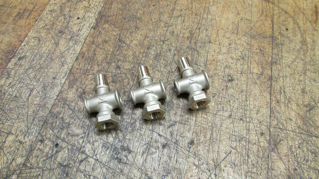
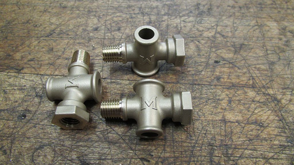
Morrison and Marvin supply these beautiful bronze investment cast hand cocks. These are scaled directly from originals of the same period.

To properly make these valves there really is no getting around having to make some fixtures. I thought about this a lot (procrastinated) about how I was going to do it. Having access to rapid prototyping equipment at work I decided that I would like to try making some machining fixtures on the 3D printers.
So maybe part of this segment should be titled adventures in 3d printing.


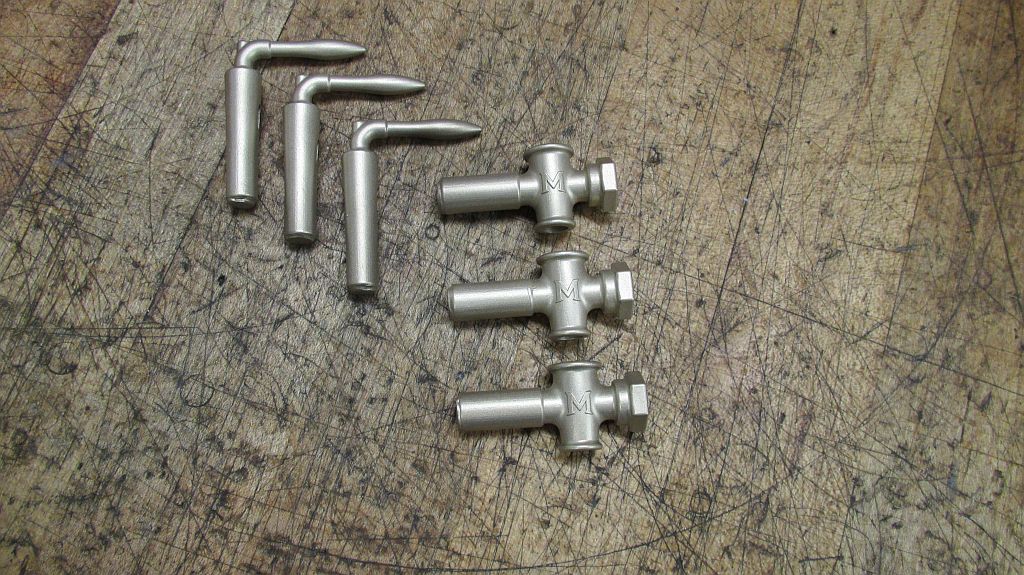
Here are the valve castings from Morrison and Marvin. I did just a little fettling to remove the mold lines and then a trip through the bead blaster which restored the original finish.


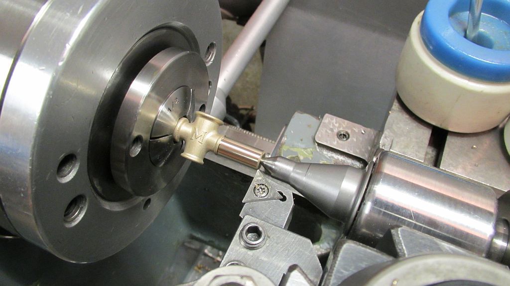
Starting with the body castings; they were held in a hex collet and indicated in. Carefully the end was faced and center drilled. The main diameter was turned and a notch cut as a reference to where they would be cut off.


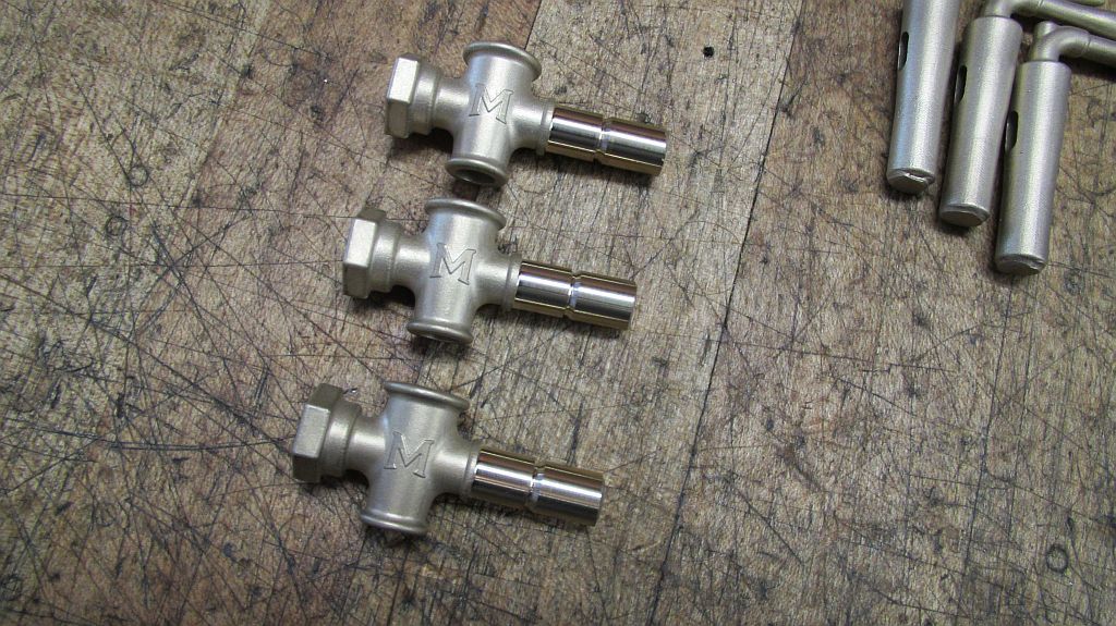
Here are the bodies ready for the next operation.


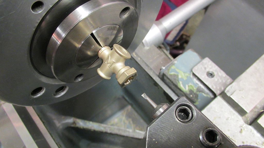
Flipped around and held in a collet the bore for the ID thread is opened up with a boring bar to maintain concentricity with the opposite end.


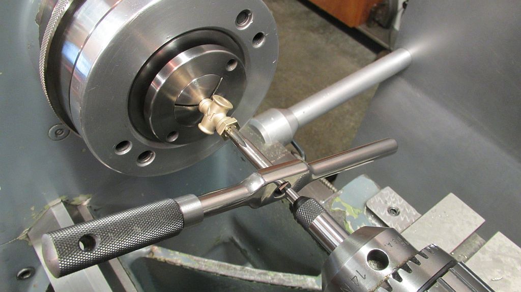
The 1/16” NPT or 5/16”MTP is taped using a guide in the tailstock.


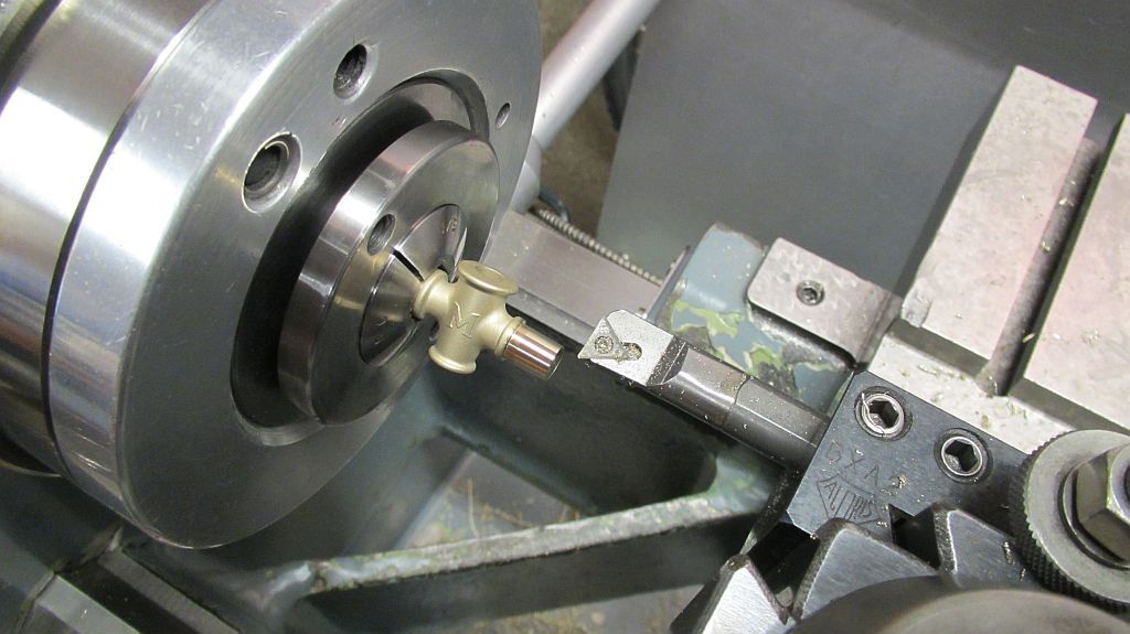
After the bodies have been cut and faced to length the taper for the pipe thread is machined using a boring bar. Also the hole through the center will be drilled.


Here are the three bodies ready to have the threads milled. A couple of reasons for wanting to mill the threads; this something I have never done and will (hopefully) result in better threads than with using a die.


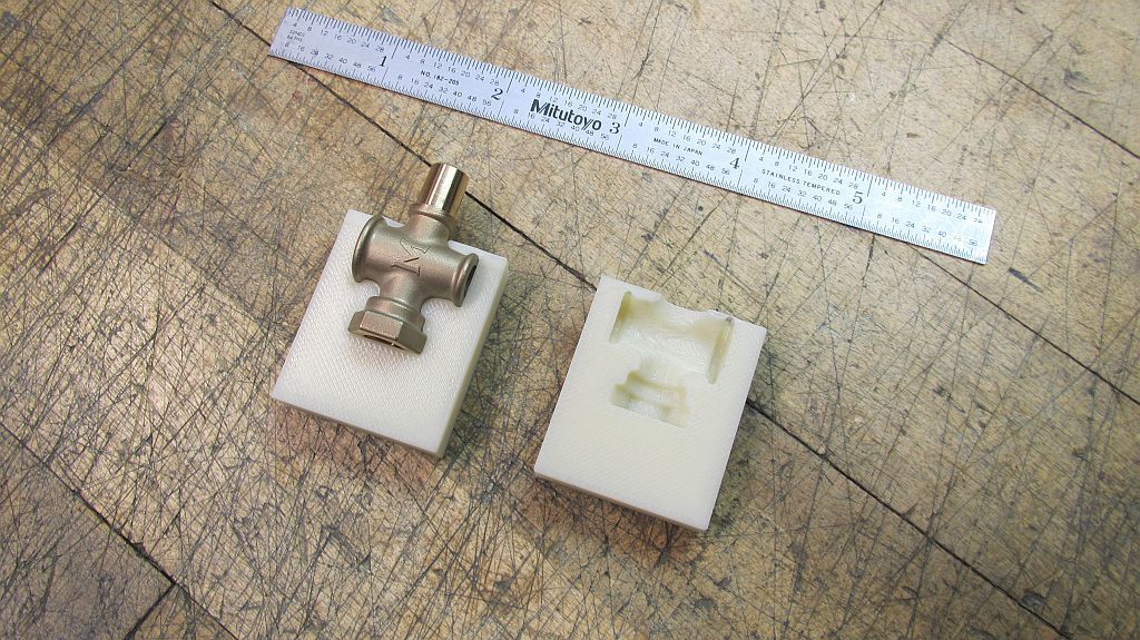
Here is my first printed fixture; this one done on a FDM machine (Fused Deposition Modeling) the most common 3d printer you see these days.


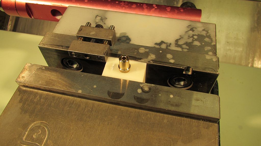
The assembled fixture in the mill ready to mill the threads. This type of fixture could also easily be used in a 4 jaw chuck.


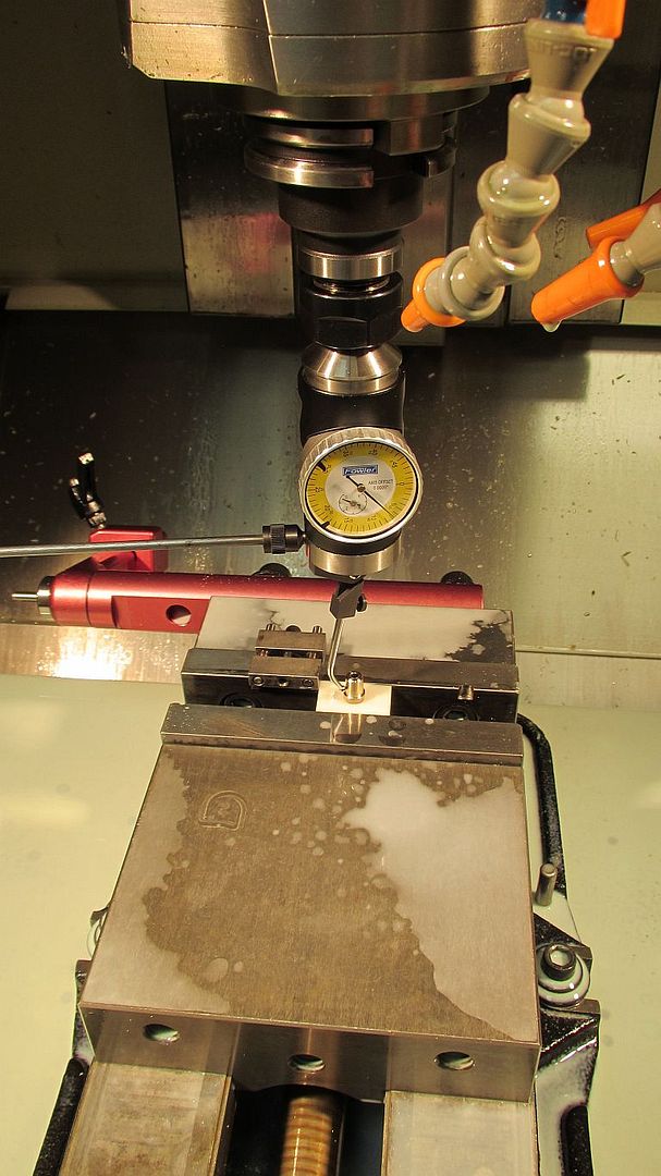
I indicated each one in but surprisingly they were all within a couple thou of each other.


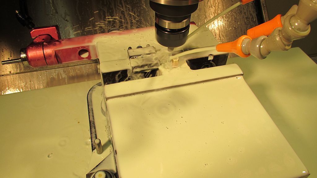
Here is an action shot of the thread milling operation.


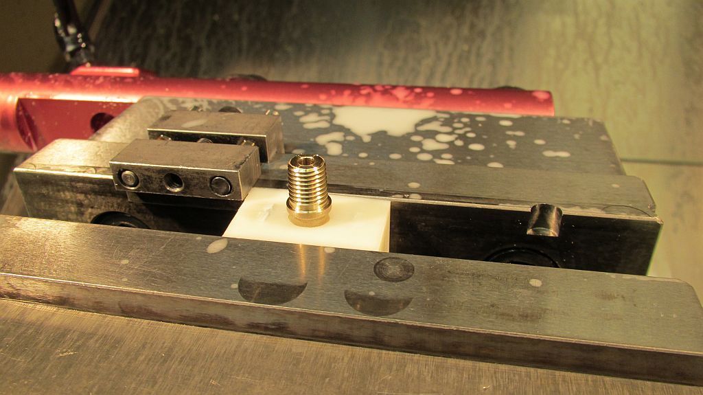
With just a little tweaking I was getting an acceptable thread; I did run a couple of aluminum dummy parts to get it dialed in.


The three valve bodies ready for the next operation.

I kind of went overboard on the pictures so I will post more later.

Thanks for checking in,
Dave
 
Last edited:
They're some lovely castings you've got there, Dave, and a very clever idea on 3D printing your fixtures. We've got a 3D printer here, and whilst I've used it to print prototypes, I'd never considered tooling - thanks for a great tip!
 
Hi everyone

Before I continuing on with the body machining I wanted to get the handle plugs machined; this way I would have a gage to know when I had bored the bodies deep enough.

This operation required the next fixture; this one was done on our SLA (Stereo Lithography) machine. The SLA builds parts by rastering a laser across the top surface of a vat of UV sensitive resin. The part is built in .003” layers and drops deeper into the vat as the parts are built. The SLA is one of the most accurate of all the rapid prototyping machines.


Here is the fixture along with the handle plug casting.


Assembled and ready for the mill


Like before each part was indicated in; but this proved unnecessary as they were all within a couple thousandths.


A small program was created that faced to length, machined the two diameters, cut the flat, milled the threads, chamfered the end and centered drilled it. Here is the result; as before a couple of aluminum test parts were machined to check the program.


Here are the 3 handle plugs ready for the next operation.


Notice the rather large hole; I’m sure this was fine for a full sized engine but on a model it will make it a challenge to get the mixture set properly.


My attempted solution lies in this little pile of brass parts.


After machining they were given several center punch marks to allow room for the solder to flow.


Assembled in the handle plug; they were left long and will be machined along with the rest of the taper.


Here are a couple of shots just after soldering the inserts in place.


The diamond orifice pattern is typical of the gas valves used on some of the early stationary engines


After another trip through the blast cabinet the handle plugs were set up to machine the taper; instead of than turning them between centers a collet was used on the #10 threaded end to hold the handle. Everything on this end was machined in the same setup so this worked out just fine.


Rather than grind a special tool I though what the heck the parting tool looks like it just may work; wrong application I know but using light cuts the insert parting blade did a beautiful job turning he taper on the handles.

Now we can move on to boring the bodies.

Thanks for checking in.
Dave
 
Dave
Hi everyone,

Here is the last set of photos dealing with the construction of the hand cocks.

The bodies needed to be bored and faced on each end; the top gets a tapered surface that the indicating lines will be engraved on. Another printed fixture was designed and made; I was hoping to run these on the SLA machine (Stereo Lithography) but it was booked up so I built them on one of our FDM 3d printers. This process in not as accurate and some hand work was required to get the fixture to completely close up on the body casting. Also the OD of the fixture was machined to help in the setup of each valve body.


Here is the split round fixture with the body casting in place.


Here it is closed up; each end of the body can be machined as well as the bore. Each time the fixture is put in the lathe the part is indicated in both axially and radially.


The bore is machined using a small solid carbide boring bar. The same compound setting was used that was used to turn the taper on the handle plug. The finished handle plugs were used as a gage the get the proper size of the bore


The top surface is cleaned up at the prober angle to give a nice surface for engraving the indicating lines.


A tapered plug fixture was turned to allow the body casting to be held in a 5C indexer for engraving the lines. The lines were patterned so the valve may flipped 180 and still have the handle pointing down when the valve is fully open.


Next up was the thrust washer with a D shaped hole; there was some discussion about this a while back on the forum. I decided to go for the fabricated version as opposed to making a punch.

A couple bits of 660 bearing bronze were silver soldered together after drilling the proper sized hole and milling it down to where the flat is located.


Indicated in the Sherline 4 jaw chuck the first side of the washer was machined and then parted off.


Flipped around and held in a collet the bottom sided was profiled and polished.


The SLA handle fixture was modified to expose the area of the handle where the pointer goes. Set up in the mill, the pointer hole was drilled. The pointer is a piece of .032” music wire cut sharpened and Loctited in place. The washers and nut help align the handle in the fixture because the fixture was designed the hold the raw casting and not the machined one.


The last two shots are of the completed valves ready to be installed on the engine; it sure was nice have that little project behind me. Had I been thinking I may have bought a few more castings and made some spares for possible future project.

Thanks for checking in.

Dave
 
I have to say this is one amazing thread. I just wasted a couple of hours salting on page one and going all the way through to the end. This is one amazing build.
 
Thanks for the kind words,

I have been side tracked by a couple other projects and really need to get back and do some more work done on the Pacific.

Dave
 
Hi Dave,

This is some really high quality work, thanks so much for sharing. I've only read this page, but I'm going to set aside some time to read through the whole thread.
 
LMAO!! I know exactly where you're coming from about getting sidetracked - the compound and two more designs have had me offof the entablature for a while now ;D
 
LMAO!! I know exactly where you're coming from about getting sidetracked - the compound and two more designs have had me offof the entablature for a while now ;D

"Gets Sidetracked" is my Indian name.:p:)
GUS
 

Latest posts

Back
Top