idahoan
Well-Known Member
- Joined
- Oct 7, 2008
- Messages
- 594
- Reaction score
- 210
Hello everyone,
First I want to say how much I have been enjoying everyone’s build threads and I know that I don’t comment on them and the updates nearly enough. There is really a lot of great work going on here (My favorite place on the net).
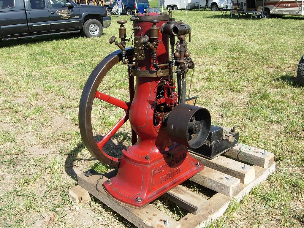
So I thought I would start a thread on my current project; it is an 1890 Pacific Vapor Engine from Morrison and Marvin castings. The engine was originally modeled by Lester Bowman who did a beautiful job making patterns and drawings. Lester made an engine for himself and there may have been some extra castings produced at that time but I don’t know for sure.
Roland Morrison took Lester’s (beautiful) original wood patterns and has been painstakingly using them as masters to create foundry proof match plate patterns from Dyanacast resin for a small run of castings.
The castings that I am using for my engine are from Morrison & Marvin’s new match plate patterns.
This is apt to be a long build because; well I have a real job, family and other things that take up my time. But I am committed and will do my best to keep on track.
I have a few parts made to date so for a while I will be playing catch-up. I started with machining the base (seemed logical) so that is where I will start this build.
Dave
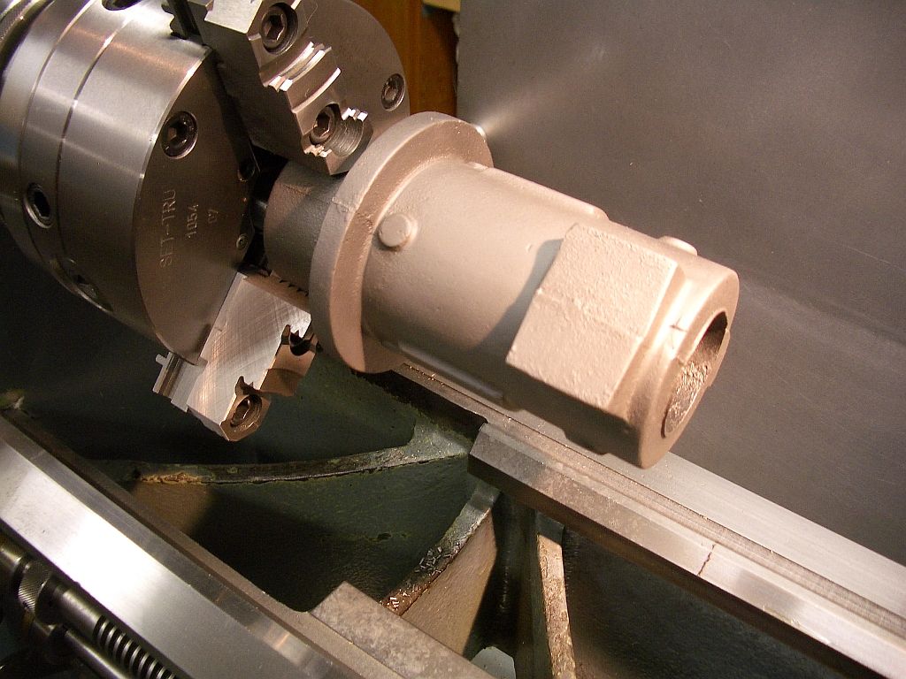
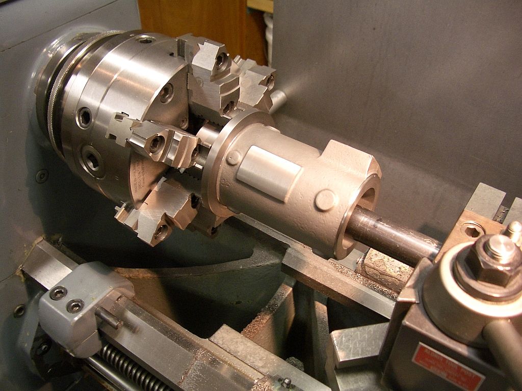
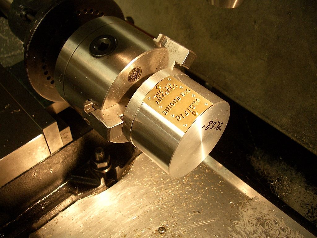
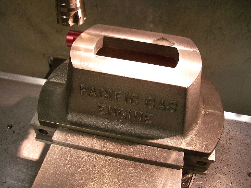
The base casting as received
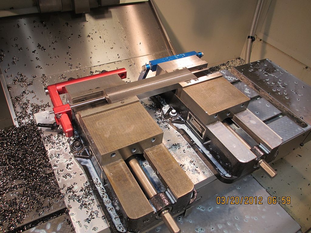
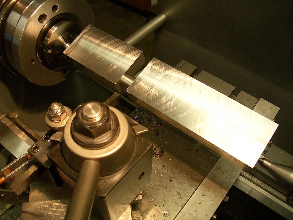
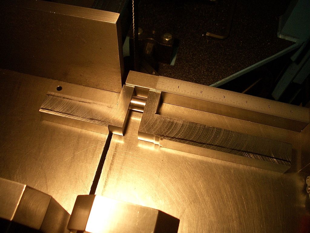
Indicated, shimmed and ready for the first cut.
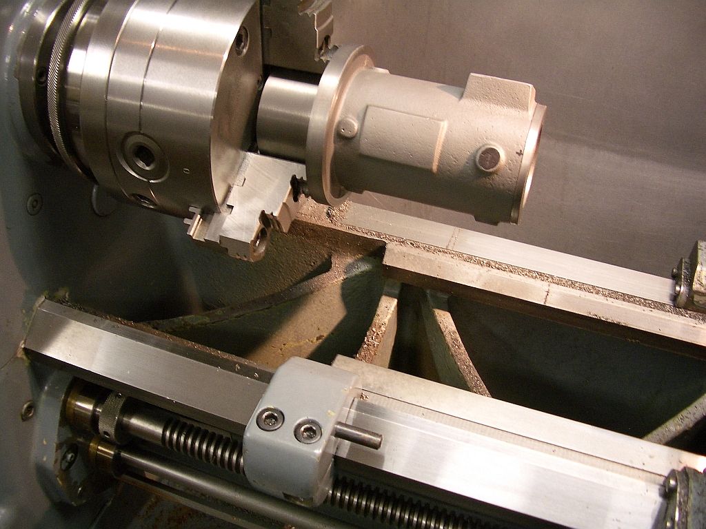
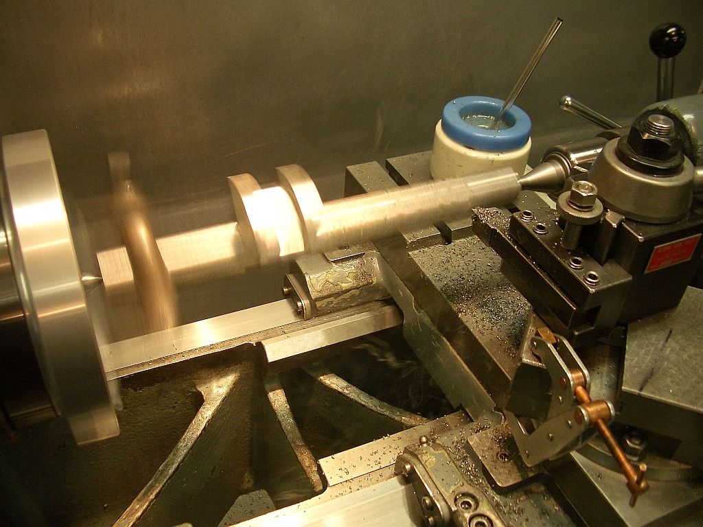
Clean up cut of the top surface
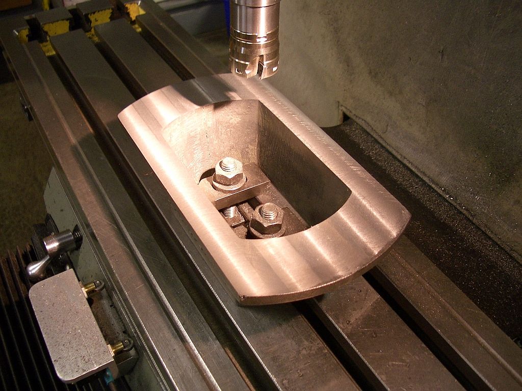
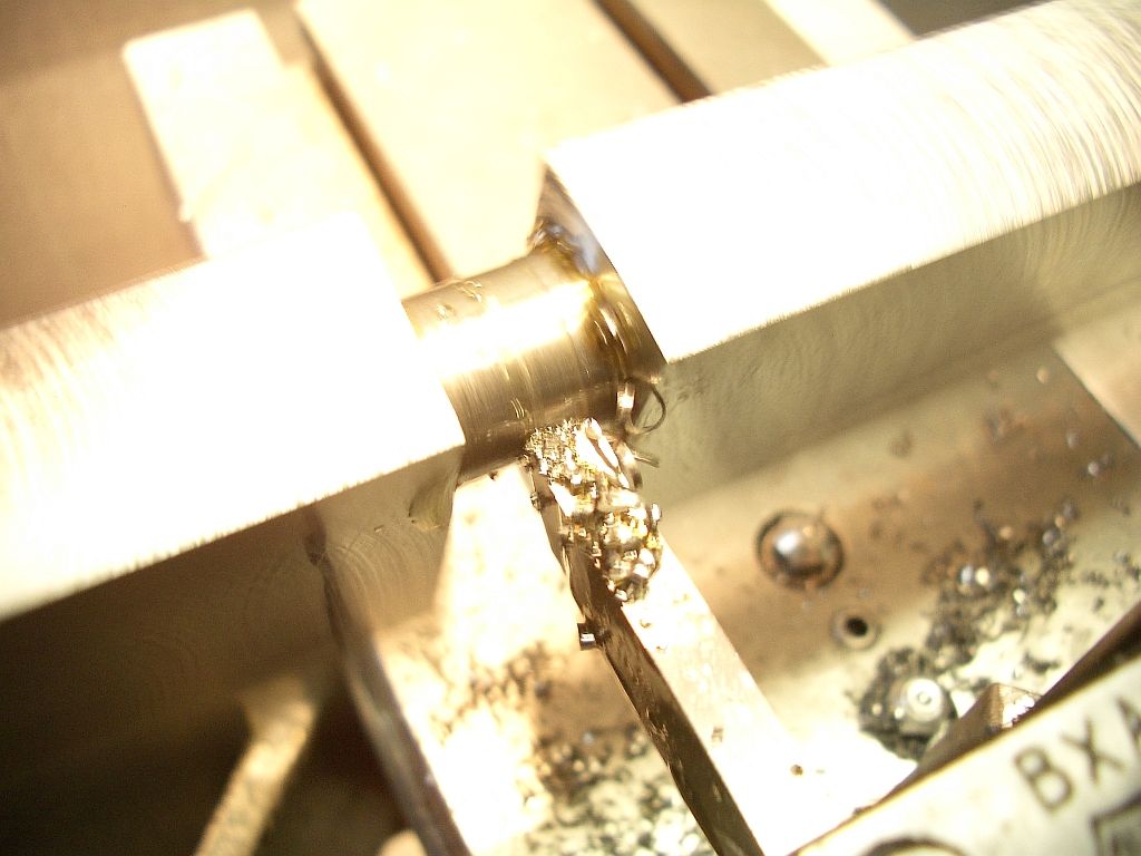
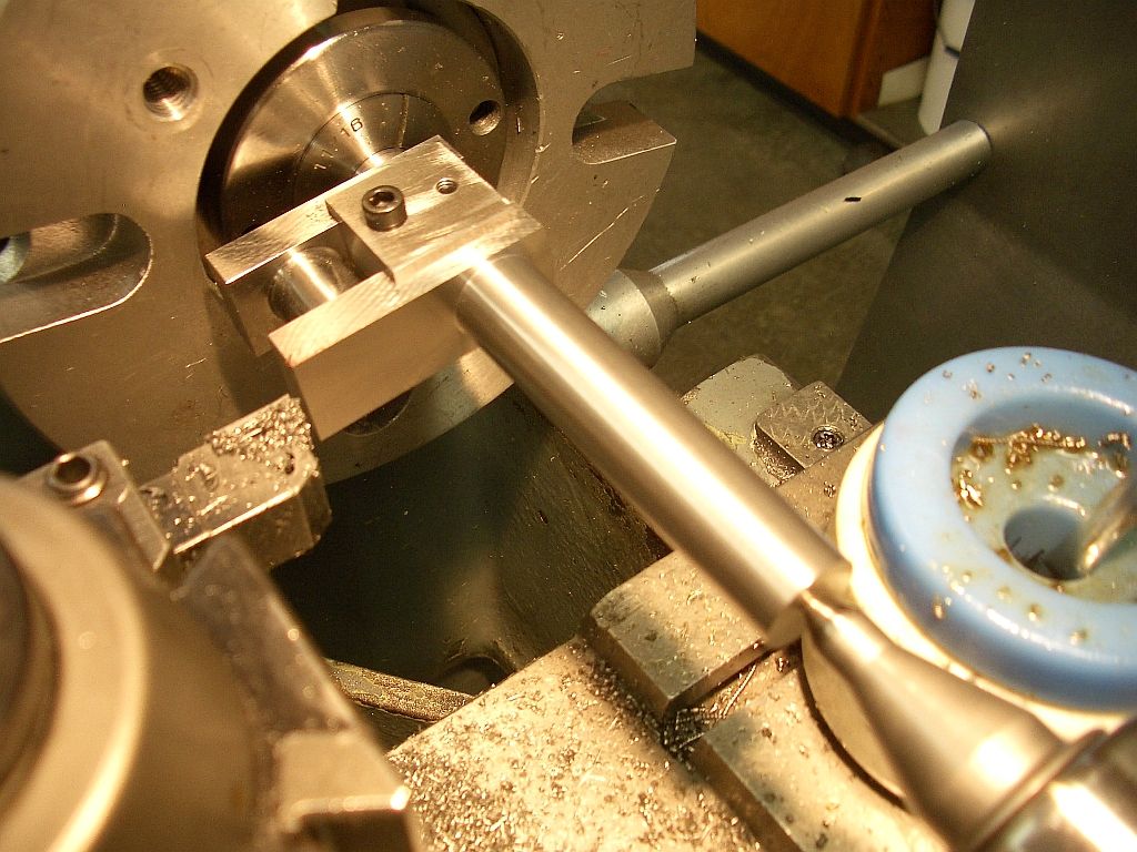
Flipped over and the bottom cleaned up
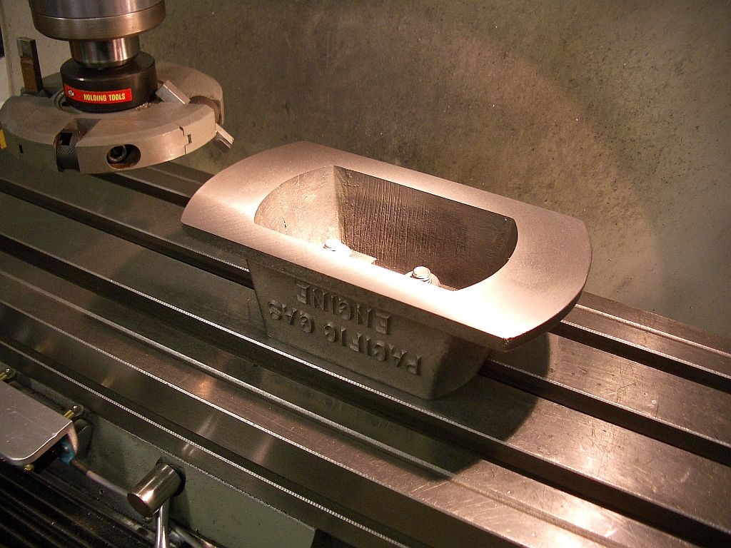
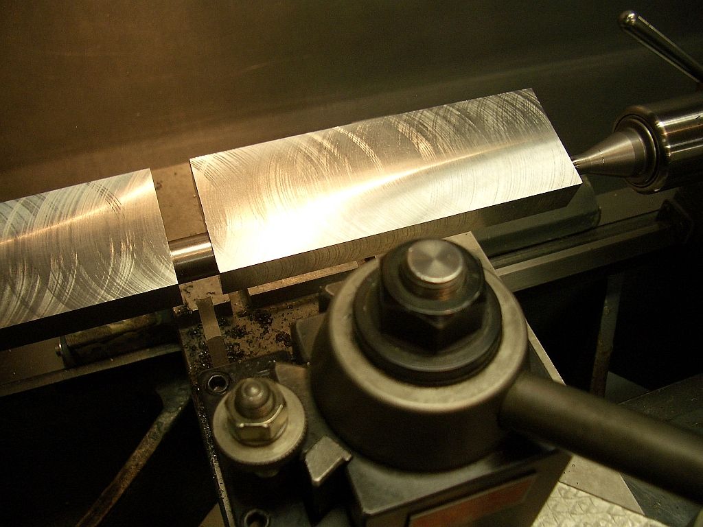
Then a light skim cut with the Newfield flycutter for a nice finish
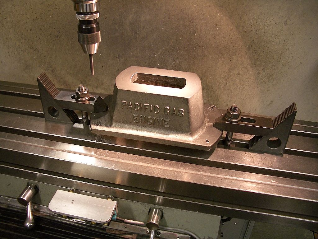
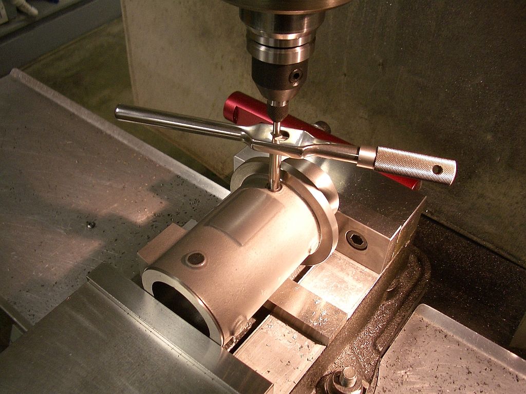
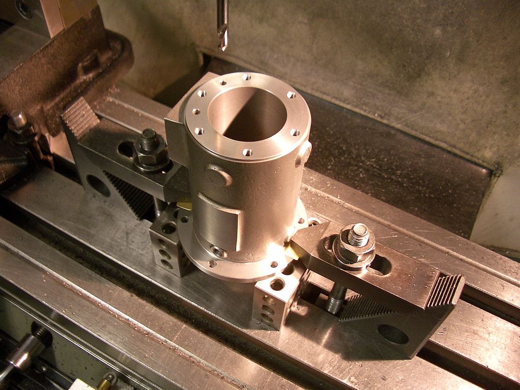
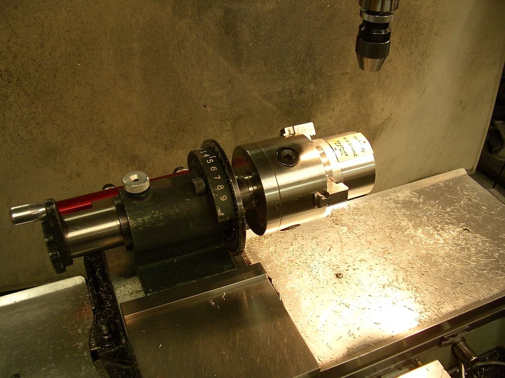
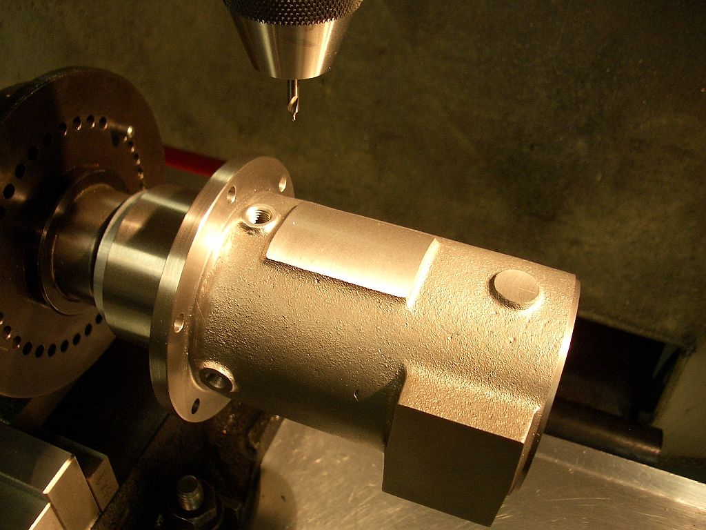
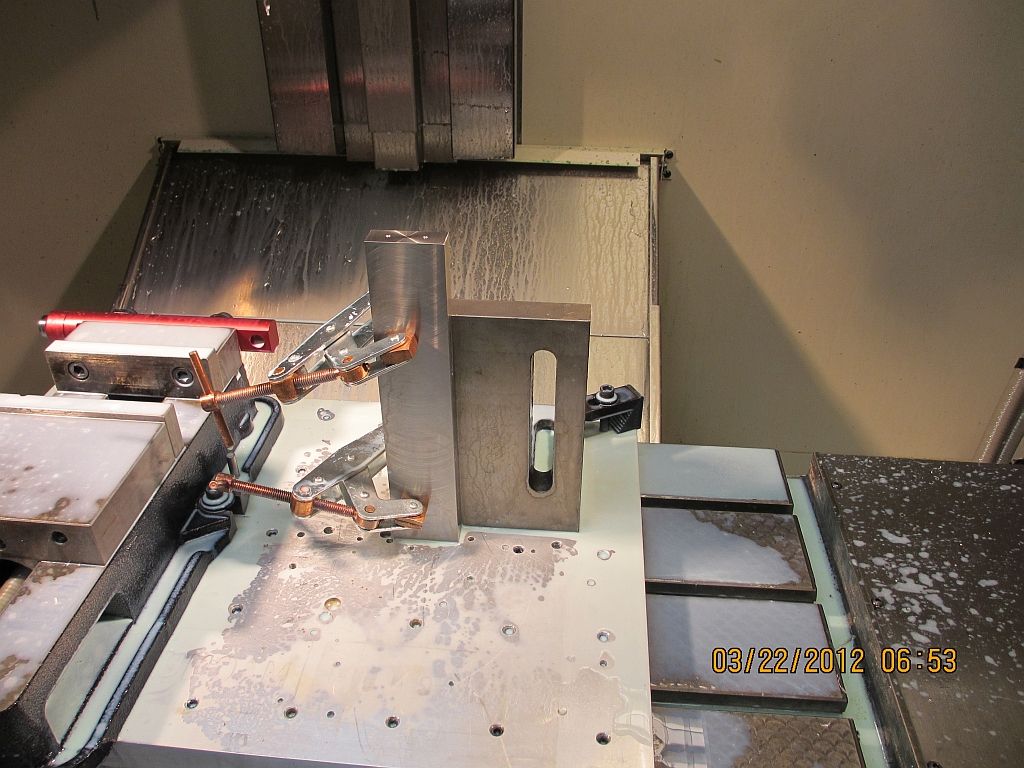
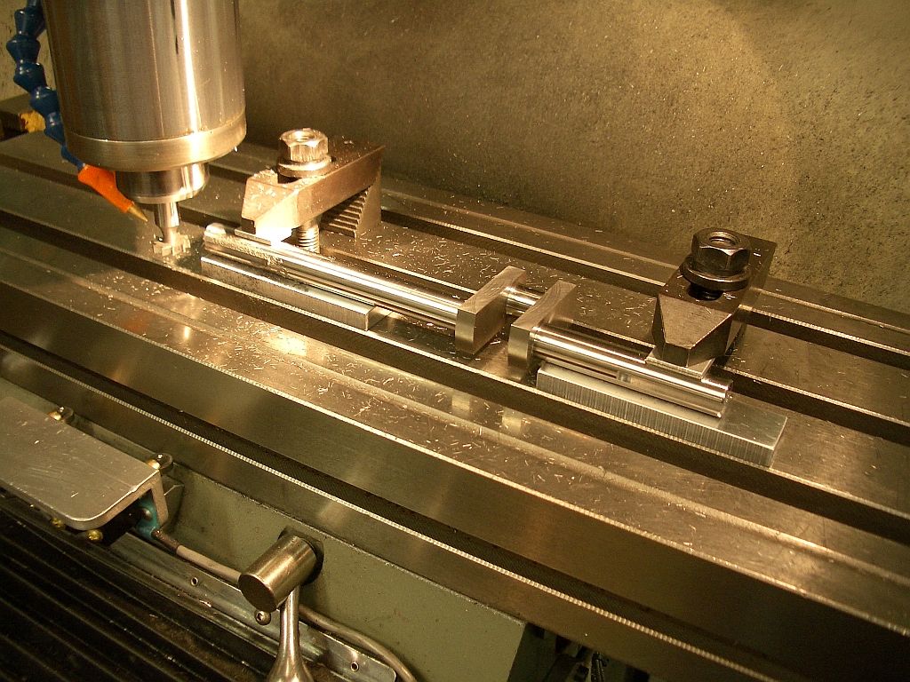
Set up to drill the mounting holes
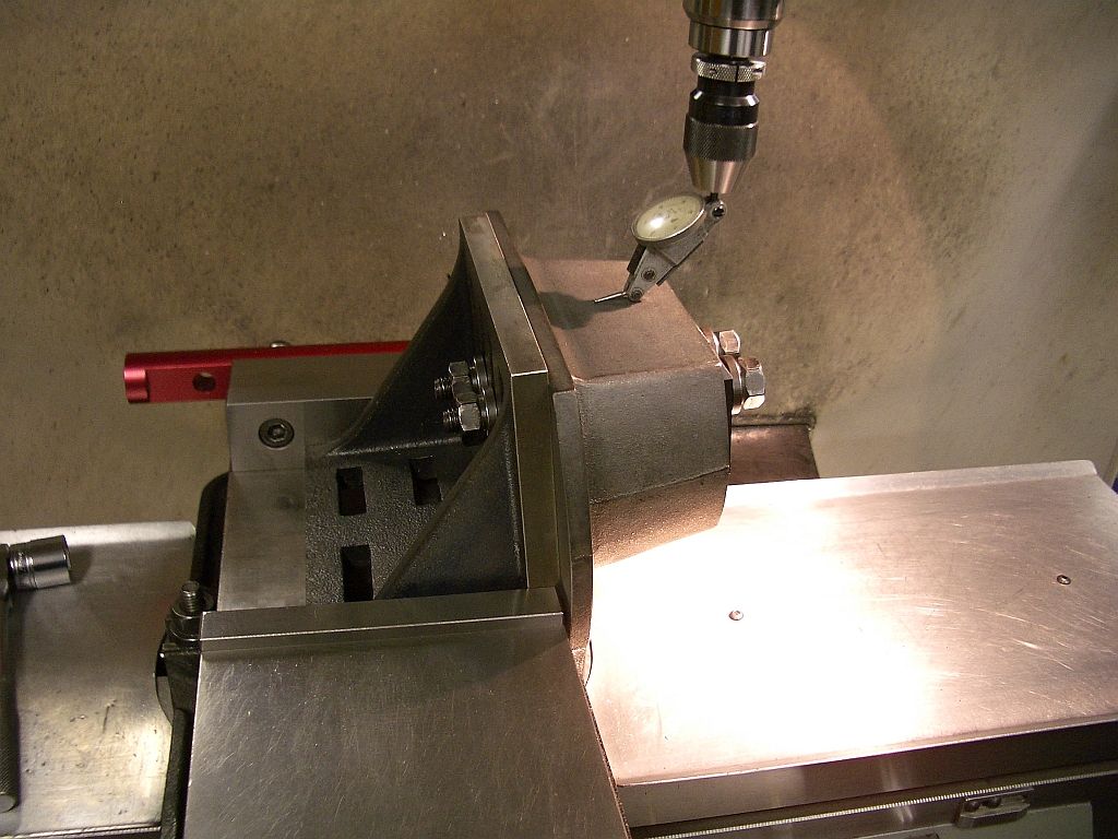
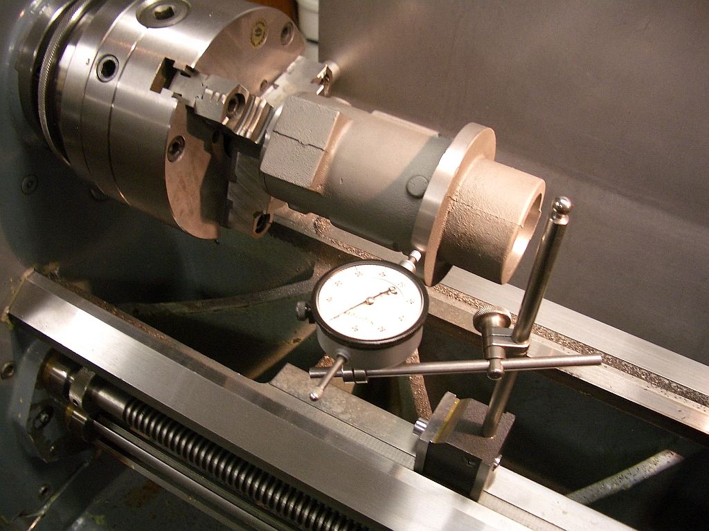
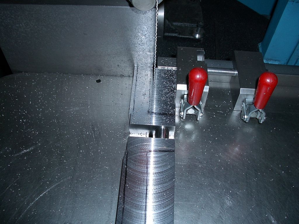
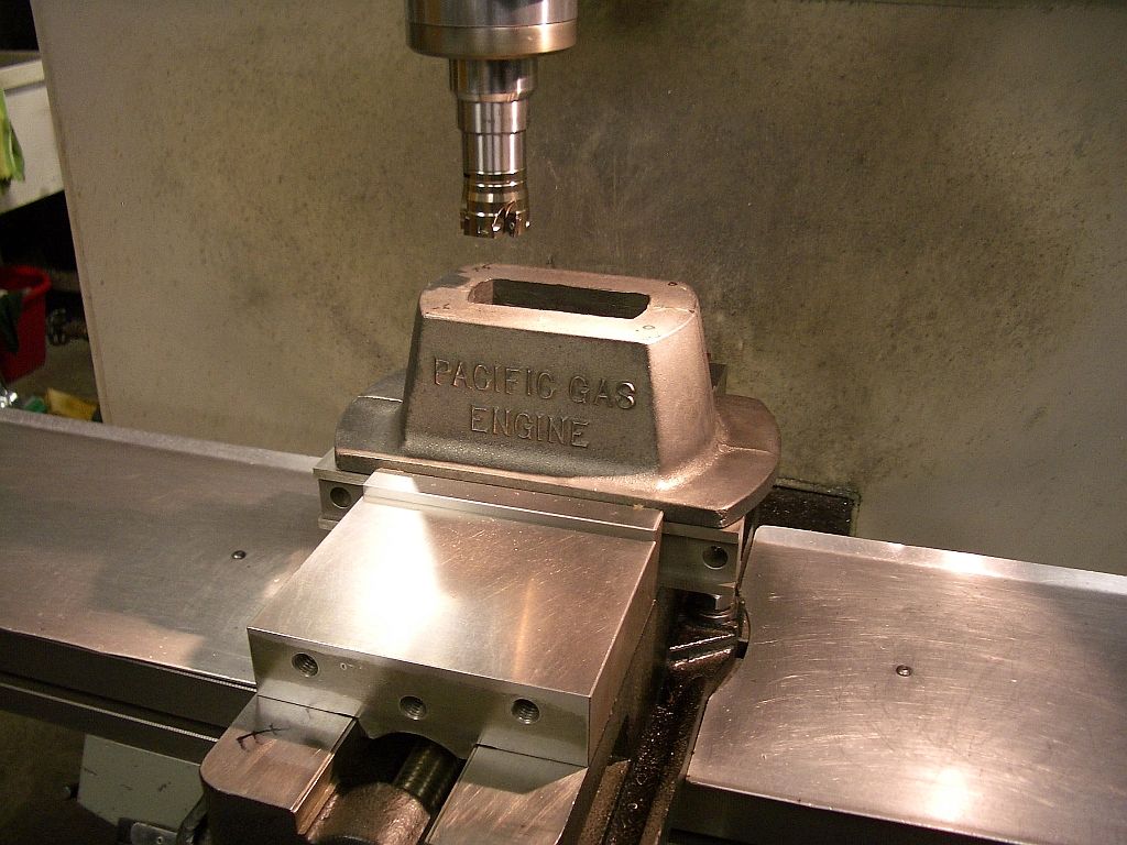
Indicating the base prior to drilling the air intake hole pattern.
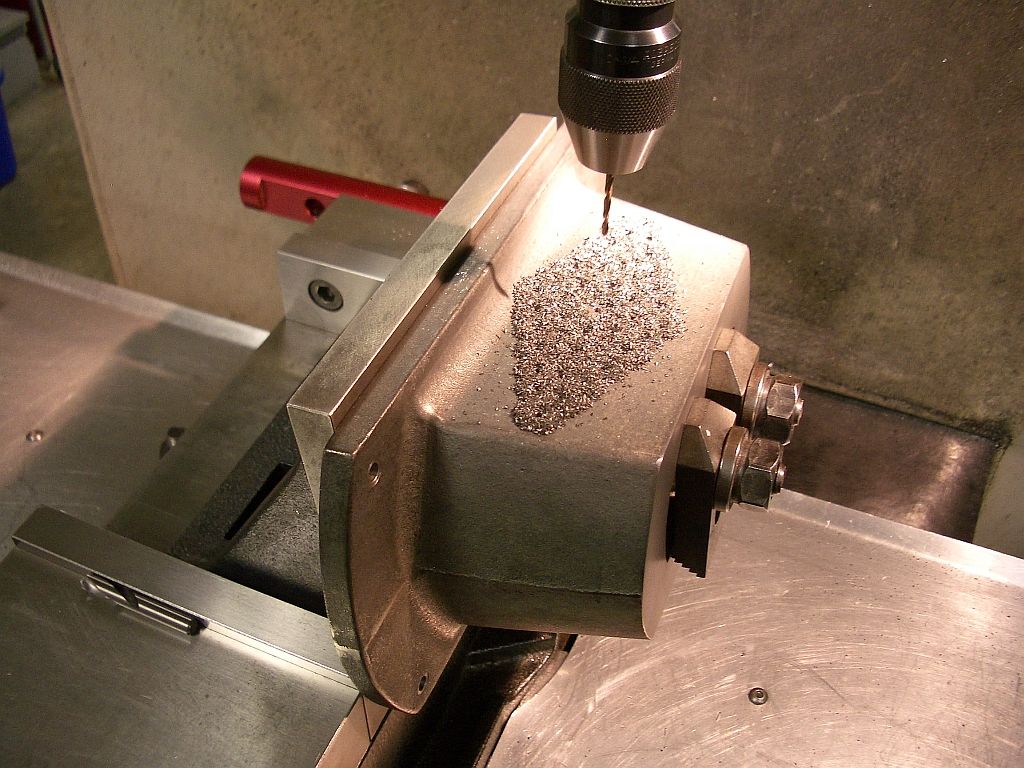
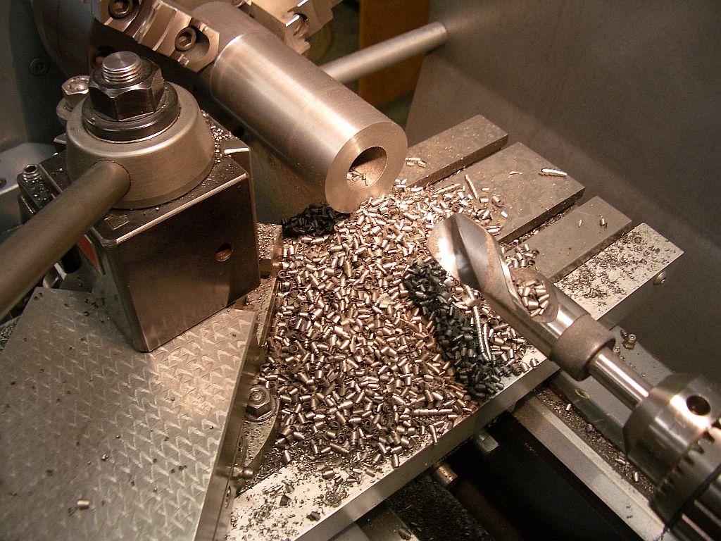
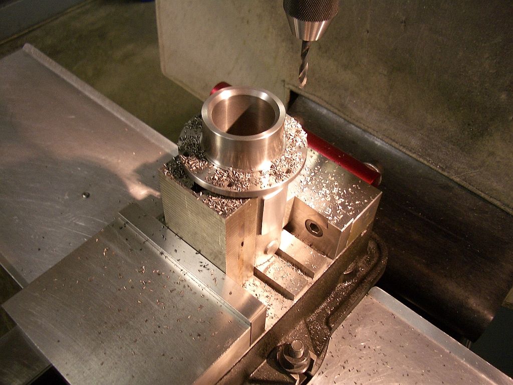
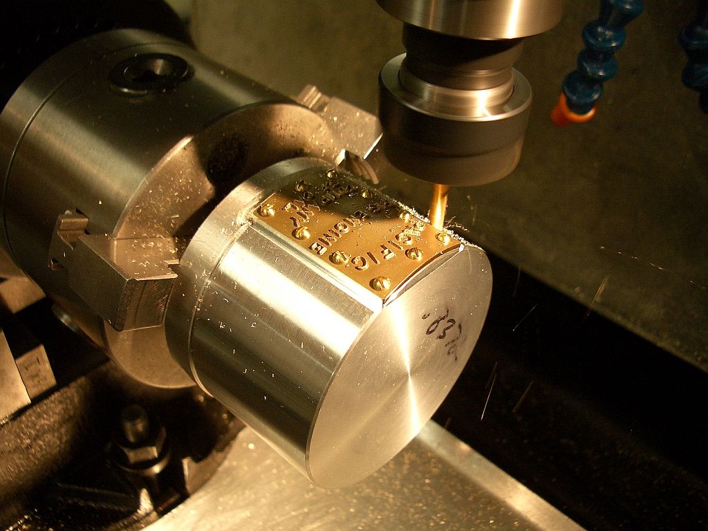
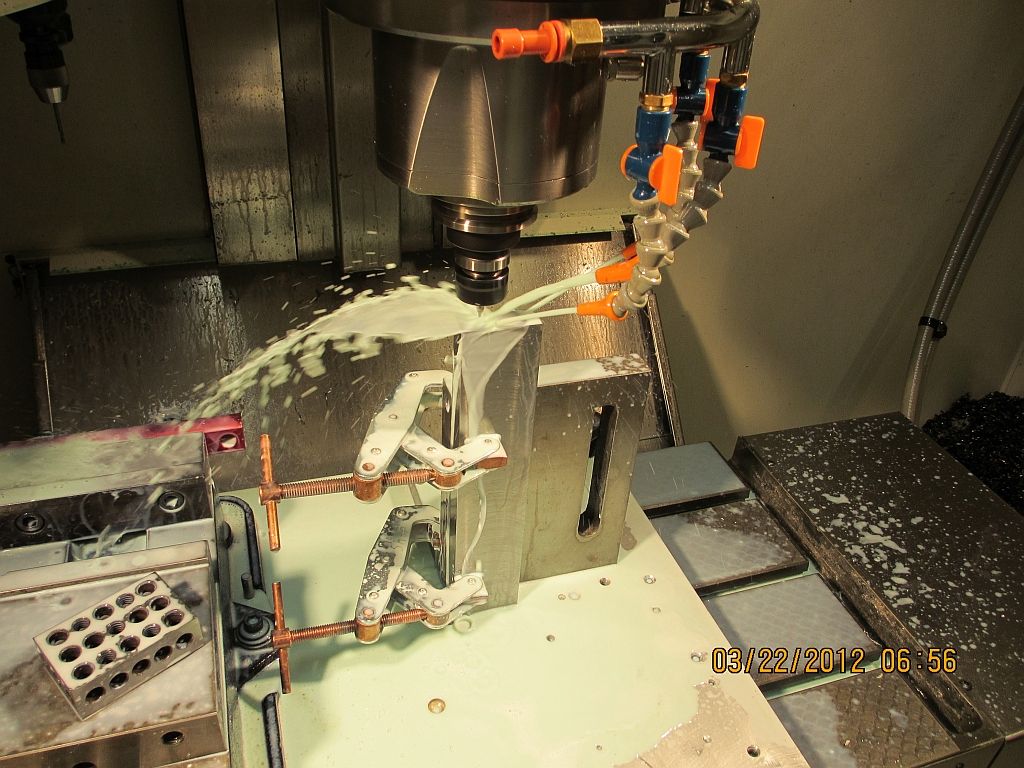
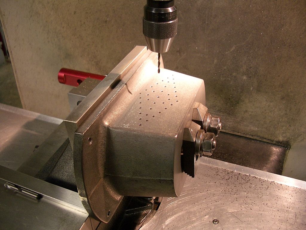
In the process of drilling.
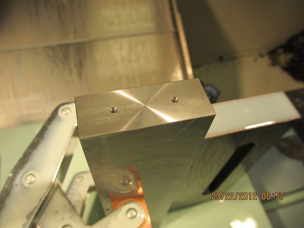
Chips removed; Nice!
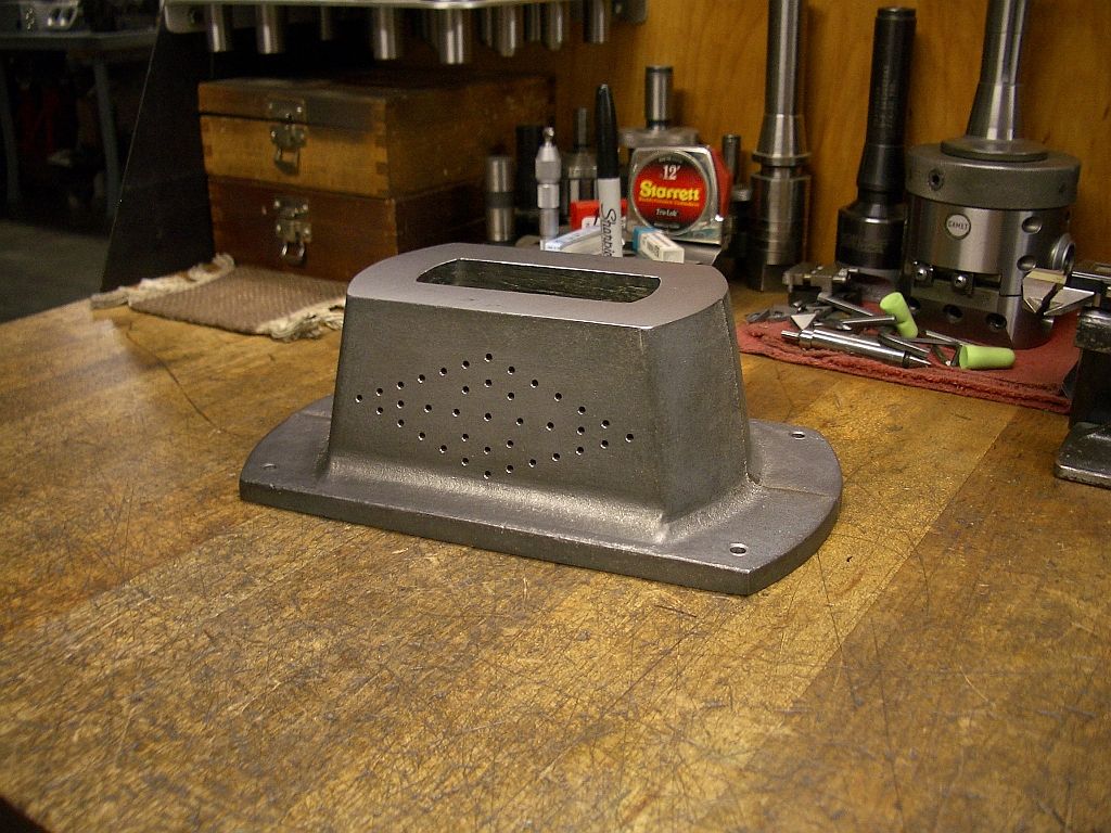
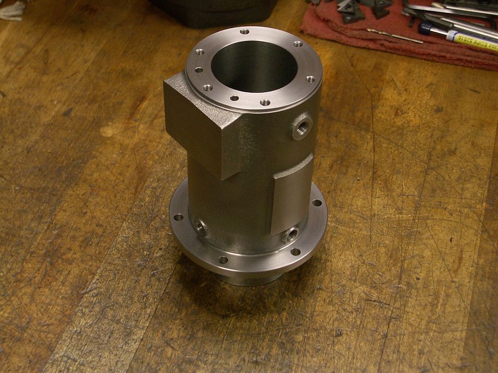
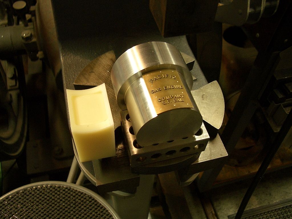
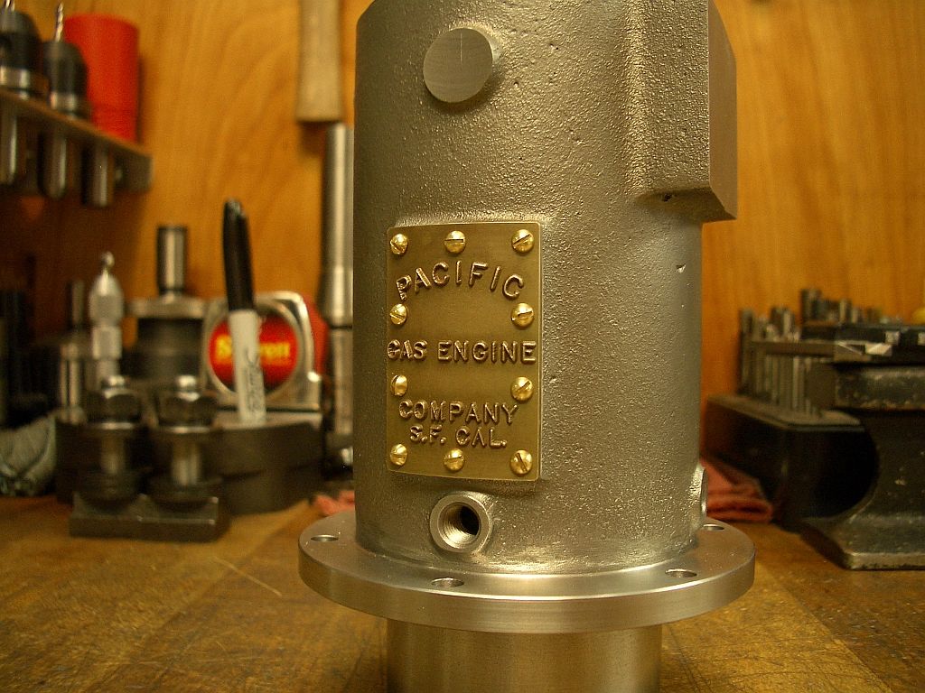
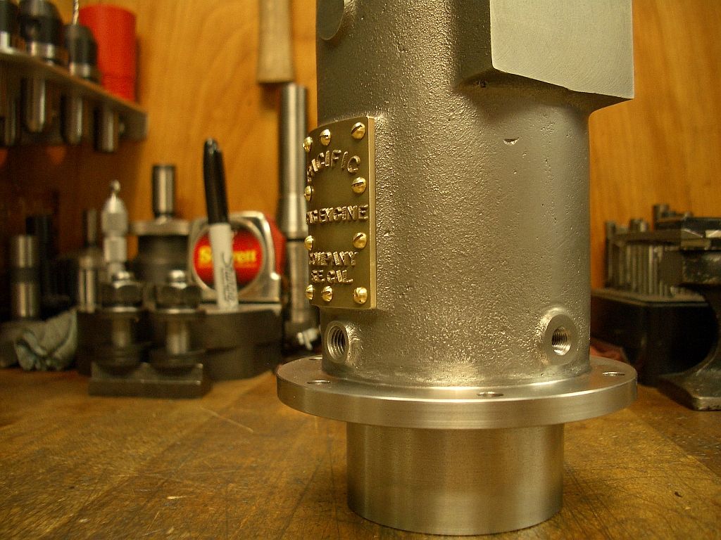
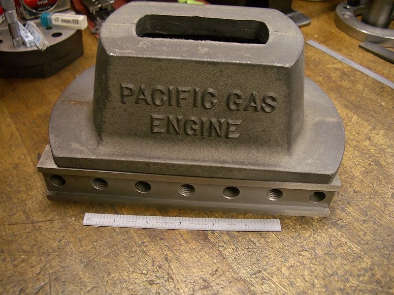
Here is the finished base except for the body casting mounting holes and intake pipe hole which will be drilled and taped later; after the body is machined.
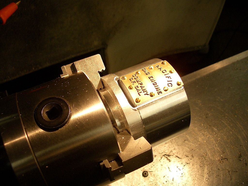
The Pacific engines have this unique and pleasing diamond shaped air intake hole pattern. The air intake pipe will be plumed into the base where the engine will pull its air from.
I guess some of the early engine manufactures felt the air in the confines of the base would be cleaner.
More to follow and thanks for checking in,
Dave
First I want to say how much I have been enjoying everyone’s build threads and I know that I don’t comment on them and the updates nearly enough. There is really a lot of great work going on here (My favorite place on the net).
So I thought I would start a thread on my current project; it is an 1890 Pacific Vapor Engine from Morrison and Marvin castings. The engine was originally modeled by Lester Bowman who did a beautiful job making patterns and drawings. Lester made an engine for himself and there may have been some extra castings produced at that time but I don’t know for sure.
Roland Morrison took Lester’s (beautiful) original wood patterns and has been painstakingly using them as masters to create foundry proof match plate patterns from Dyanacast resin for a small run of castings.
The castings that I am using for my engine are from Morrison & Marvin’s new match plate patterns.
This is apt to be a long build because; well I have a real job, family and other things that take up my time. But I am committed and will do my best to keep on track.
I have a few parts made to date so for a while I will be playing catch-up. I started with machining the base (seemed logical) so that is where I will start this build.
Dave
The base casting as received
Indicated, shimmed and ready for the first cut.
Clean up cut of the top surface
Flipped over and the bottom cleaned up
Then a light skim cut with the Newfield flycutter for a nice finish
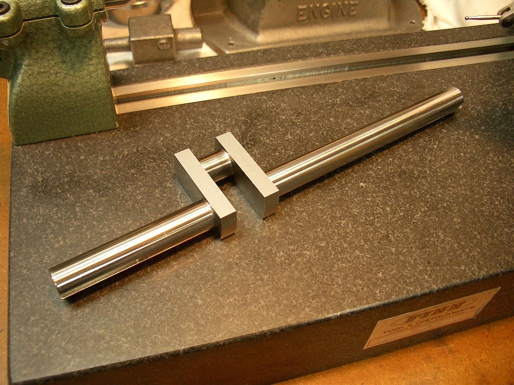
Set up to drill the mounting holes
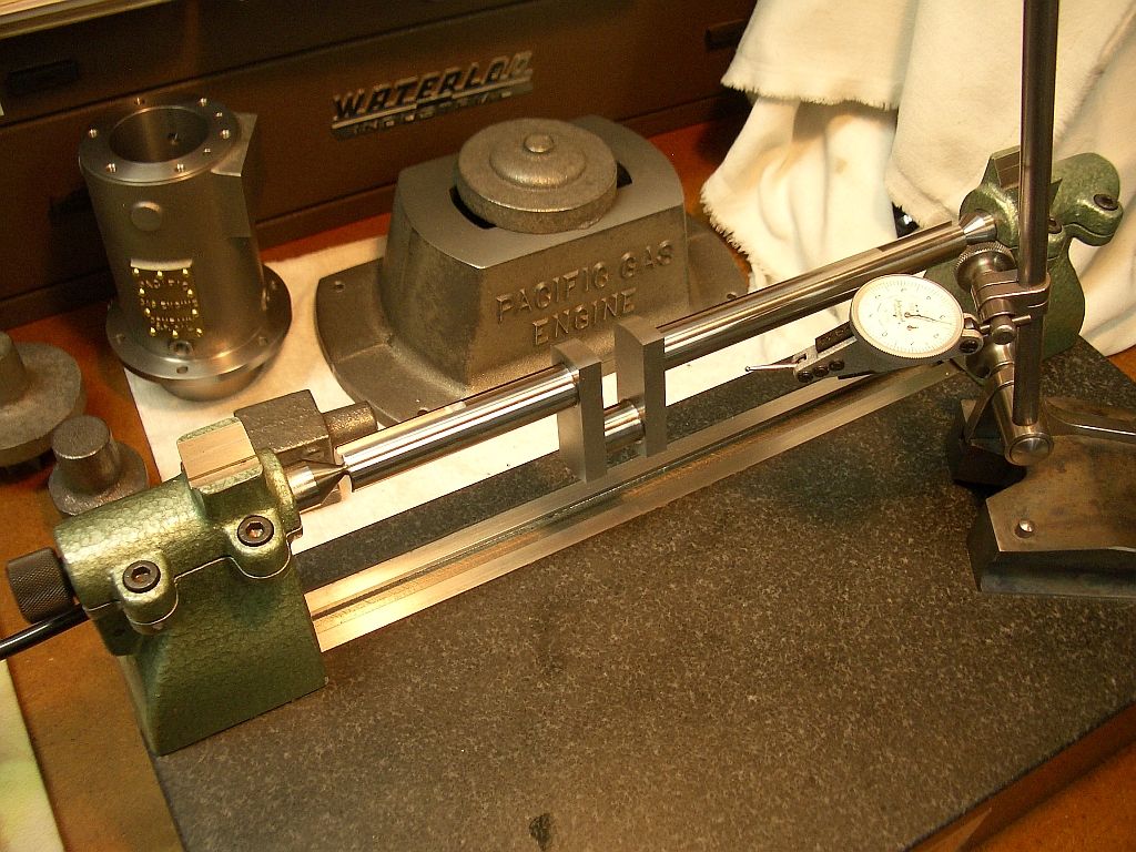
Indicating the base prior to drilling the air intake hole pattern.
In the process of drilling.
Chips removed; Nice!
Here is the finished base except for the body casting mounting holes and intake pipe hole which will be drilled and taped later; after the body is machined.
The Pacific engines have this unique and pleasing diamond shaped air intake hole pattern. The air intake pipe will be plumed into the base where the engine will pull its air from.
I guess some of the early engine manufactures felt the air in the confines of the base would be cleaner.
More to follow and thanks for checking in,
Dave
Last edited:
")