Pacific Vapor Engine from Morrison & Marvin Castings

Home Model Engine Machinist Forum

Help Support Home Model Engine Machinist Forum:

This site may earn a commission from merchant affiliate links, including eBay, Amazon, and others.
To clarify a bit on the above questions:

1) The CNC g-code program needs to move the tool relative to the stock. So at the start of each operation, there needs to be a zero point in all three dimensions. The programmer can choose that zero point anywhere he wants. Typically the zero point in the Z axis is either the top of the stock or the bottom of the stock. Here Dave chose the bottom of the stock. That means that all the movements of the tip of the tool will be above the bottom, or positive Z coordinates.

2) For 3D milling, the programmer restricts the tool movement to within a specified volume, typically the stock or part of it. This is the bounding box. Here he needed to leave the two holding "tabs" on either end, so the bounding box excludes them from any cutting.

3) Here Dave used three different tools to get progressively finer details. For the first one, he wants to "rough", meaning removing all stock to within a given clearance dimension in all 3 axes. For the second tool, you don't need to rough, but you still need a clearance. For the final finish pass, you use a 0 clearance.

4) For 3D milling on two sides, you need to flip the part in either the X or Y direction. The CAM program will typically take that into account in generating the g-code.
 
Kvom, I undestand what you mean there, but what doesnt make sense is "What I did here was to shift my first operation in the CAM software .05” +X and –Y." it sounds like he is only off setting the work on the positive X and negative Y by .050" Thats what im trying to figure out as to why.... Im sure its something obvious that I am over looking.....Typical me LOL
 
Hi Kvom

Thanks for clearing up what I attempted to say; I'm not always very good at getting my thoughts down on paper, so to speak.

I do prefer to use the top of my part as my Z fixture offset G54 and my tools set at the bottom of the part so all Z moves will be negative; I know some guys don't like to do it this way but it works for me. As I indicated before this makes the Z fixture values easier for me to keep track of in my head.

Aonemarine

Think of the bounding box as just a piece of geometry drawn in by the CAM program; you select your part and the program draws a box around it. It can be either 2d or 3d and if you want to put an offset in to make the box larger you can do that as well; it is just a handy tool included in some CAM programs.

So on this part because it was an odd shape and I wanted to drive the cutter all the way around the stock to clean it up. The bounding box gave me a 2d box around my part that I could use for a tool path contour.

As far as shifting the offset for the first op; this just shifted my part in the CAM program so there would be material to cut on the reference surfaces (rear vise jaw, and work stop)

If you left the part at 0x0 and cut around it there wouldn't be any material to cut on the left and back sides; the end was saw cut and the back was mill finish bar.

So essentially you are just adjusting the position of the tool paths on your raw stock.
The .05" value is just a number that I routinely use; sometimes more sometimes less depending on the condition and size of the raw stock.

You could also shift your work origin in your CNC controller but when you flip your part over for second op. you would have to shift it back or the 2nd op would be shifted by the amount you changed your G54 work offset.

I not sure if any of this makes since or not; hopefully it does.

Dave
 
Makes sense now, boy am I in for a learning curve...
 
Hi everyone,

I haven’t had much time to work on the engine but I did manage to get the exhaust valve finished this last weekend.
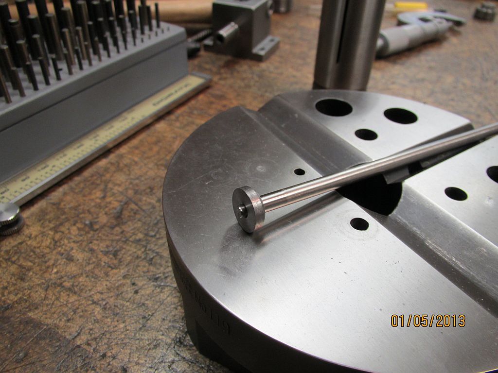
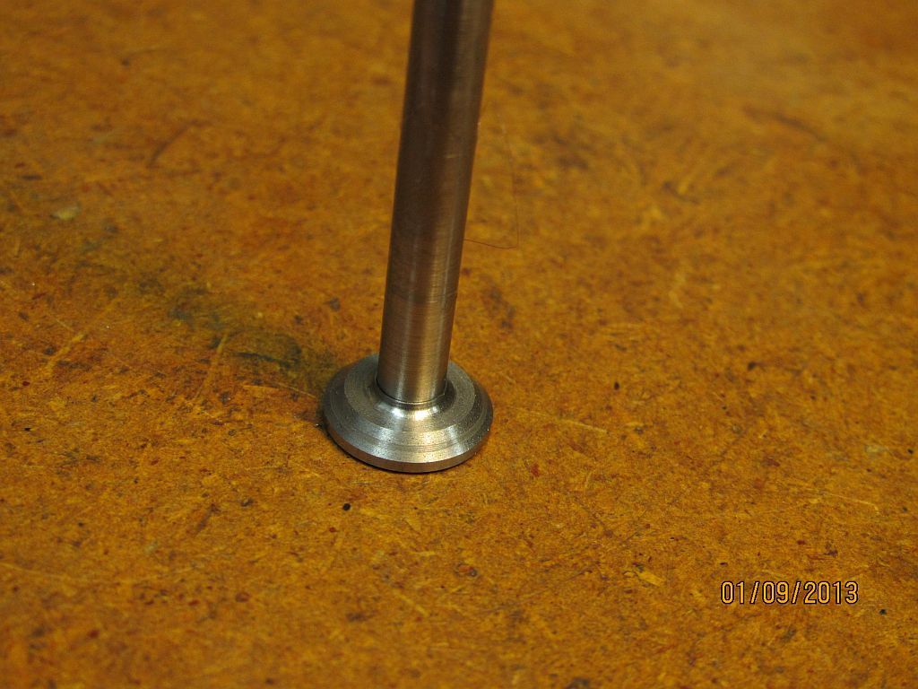
I decided to make a two piece valve using a cast iron head and steel stem; this is the way the valves on some of the old engines were made. Due the length of this valve (over 6”) this one was a good candidate.
Valve_001.jpg

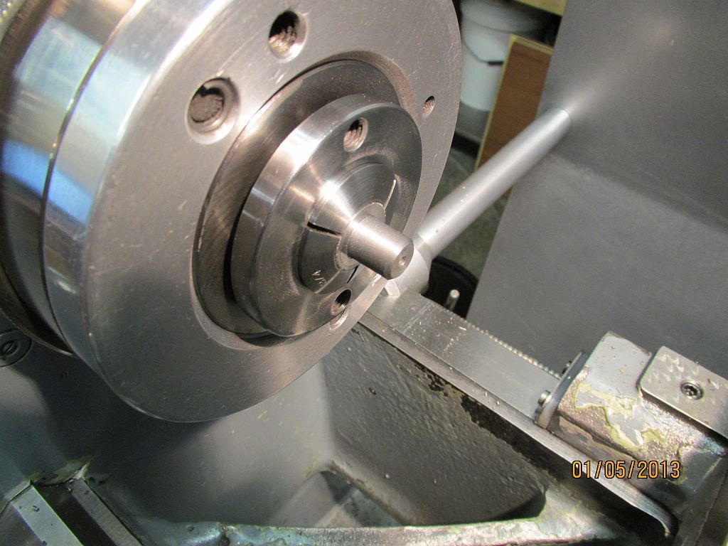
Starting with the chucking lug that was cut off of the valve chest; it was turned, faced, drilled, reamed and parted off.

Valve_002.jpg

I pressed the valve head onto a 1/8” dowel pin to hang on to while facing it to length.

Valve_003.jpg

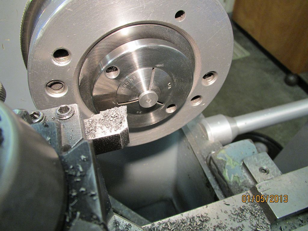
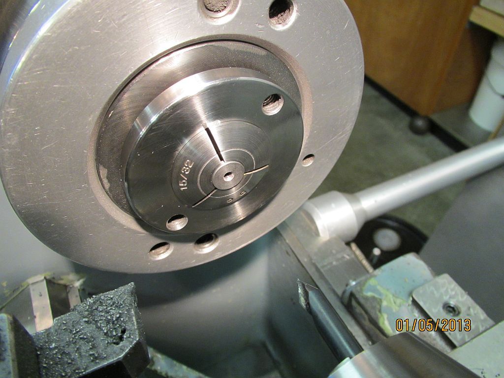
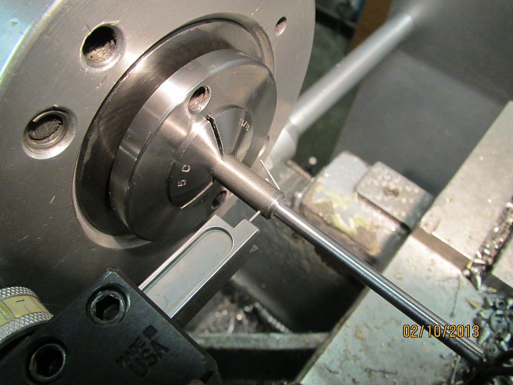
Then the top end of the stem hole was opened up with a 60 degree countersink.

Valve_004.jpg

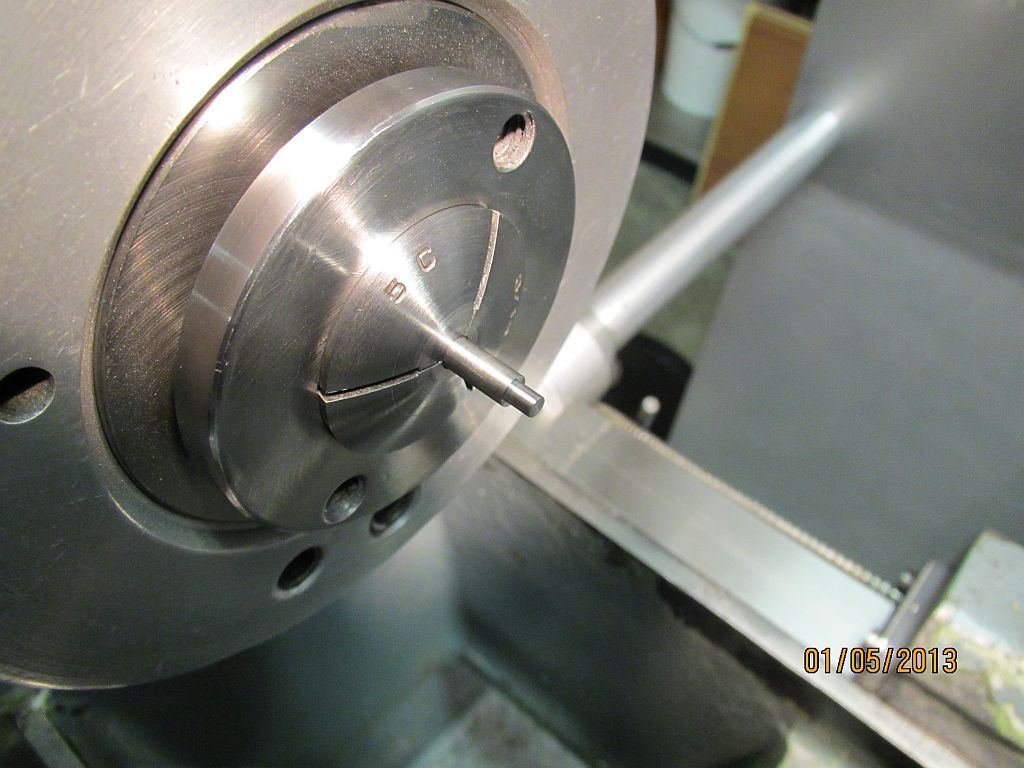
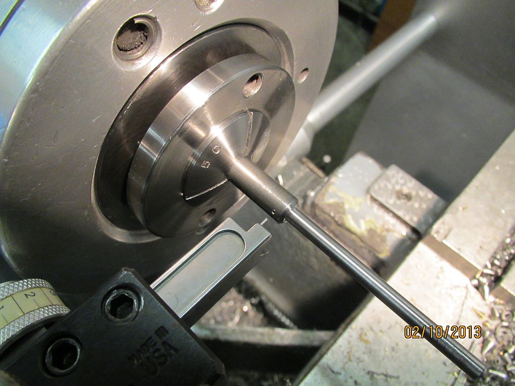
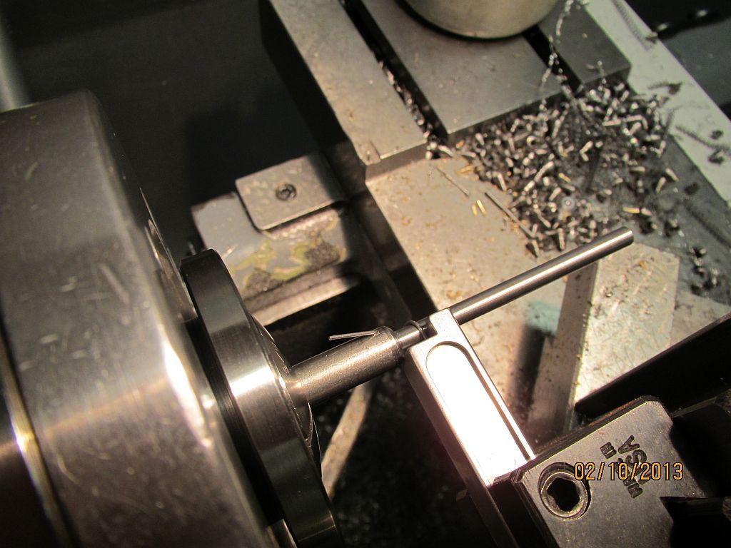
A piece of precision ground stainless rod is used for the stem. Here it is being turned for the press fit of the head.

Valve_005.jpg

The head was pressed onto the stem and is ready to be peened.

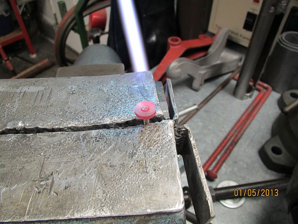
Valve_006.jpg

While heating the end of the stem with a torch the stem is peened to lock the head on to the stem. There is a piece of steel on the bench under the vise supporting the end of the valve. A few taps with a small ball peen hammer and it is done.
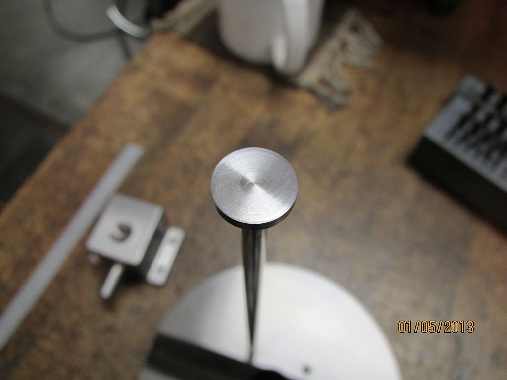
Valve_007.jpg

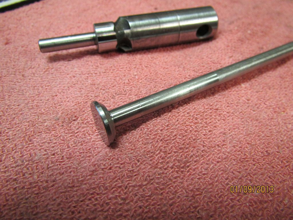
After facing the head notice the 60 degree chamfer is now completely full of valve stem. I don’t think that head is going anywhere.

Valve_008.jpg

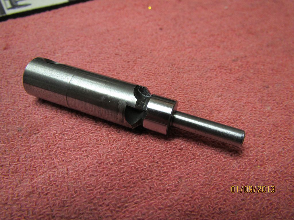
Next a seat cutter was made; ala George Britnell. I made it with 5 flutes hoping that it would have less chance of chatter.

Valve_011.jpg

Here it is after heat treating a little cleanup and stoning.

Valve_009.jpg

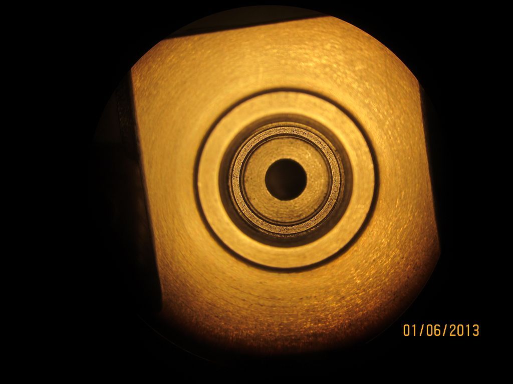
The cutter worked great; here is a picture through my microscope (wanted to see if I could do it); the valve seat shows as a dark circle near the edge.

Valve_010.jpg

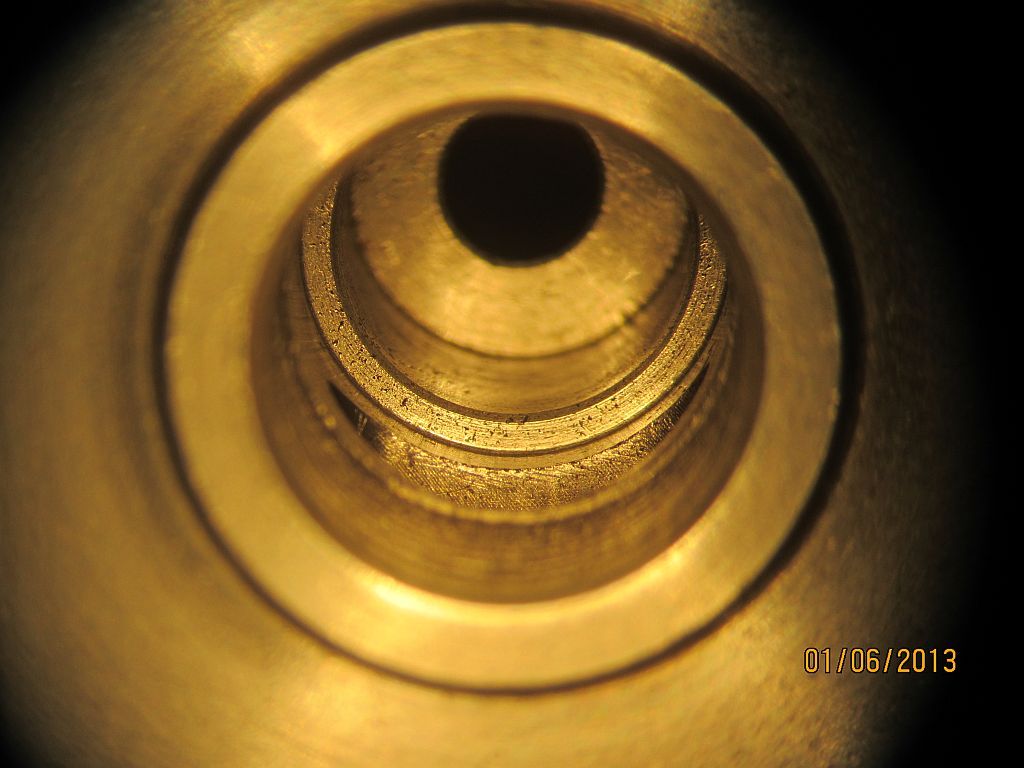
Here is another shot with the valve chest tilted a little. You can see the seat better in this picture.

Valve_012.jpg

After just a little lapping with extra fine Timesaver compound you can see the contact area on the valve.

Valve_013.jpg

Here is the completed valve next to the seat cutter.

Thanks for checking in,
Dave
 
Nice one Dave. Another way of doing the valves. Thanks for showing because it is a new method for me.

Vince
 
That's a great looking valve. Thanks for the in-depth pictures, not just of this stage but the whole process. I'm always glad to see another update in this thread when I log into the site. I know I'm going to learn something.
 
Dave, You are correct in the assembly of the valve. Many early engines had a cast iron head on a steel stem. I will attach a picture of my Pierce engine of the same era showing the rivet head on the valve.

No one however, except Dave, machined off the rivet head and polished it into a piece of jewelry. Splendid photos and explanation. Thank you

Roland

Pierce Valve.jpg
 
Vince, JLeatherman and Roland,

Thanks for the comments guys; I appreciate it. Hopefully I may get some time this weekend to work on the engine (we'll see).

Roland welcome to HMEM; your expert knowledge on this project is great asset to have here.

Dave
 
Hi everyone

I haven’t had much time for the Pacific lately but I did manage to find enough shop time to get the exhaust valve spring and keeper finished. It’s not much but at least its something.

Spring_001_zps194fc9c9.jpg

Starting out the spring wire is passed through the tensioner and then through the cross hole in the mandrel.

Spring_002_zps29cbe5a9.jpg

Then the wire is bent over to keep it from pulling out of the mandrel.

Spring_003_zps66da4e46.jpg

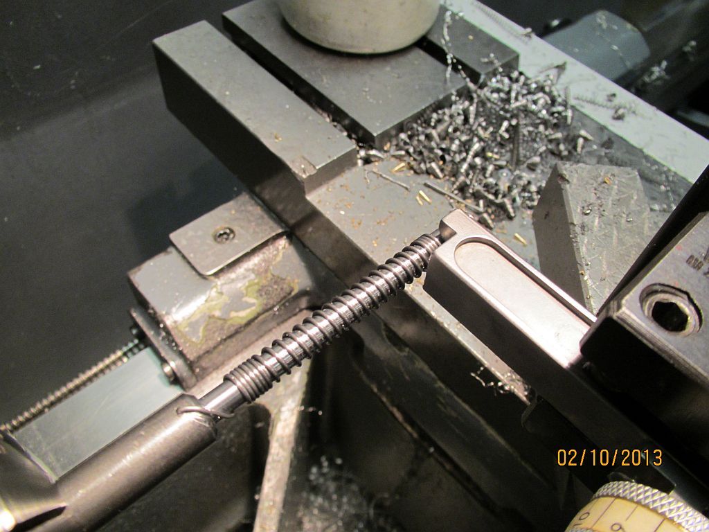
Starting the winding process; the lathe quick change is set to give the proper number of coils per inch. At first a few close wraps are completed; the lathe carriage is moved by had to keep the coils tight. Then the half nut is engaged and the carriage is moved by the gearing. I usually turn the spindle by hand making sure to keep tension on the wire.

Spring_004_zps20e33afa.jpg

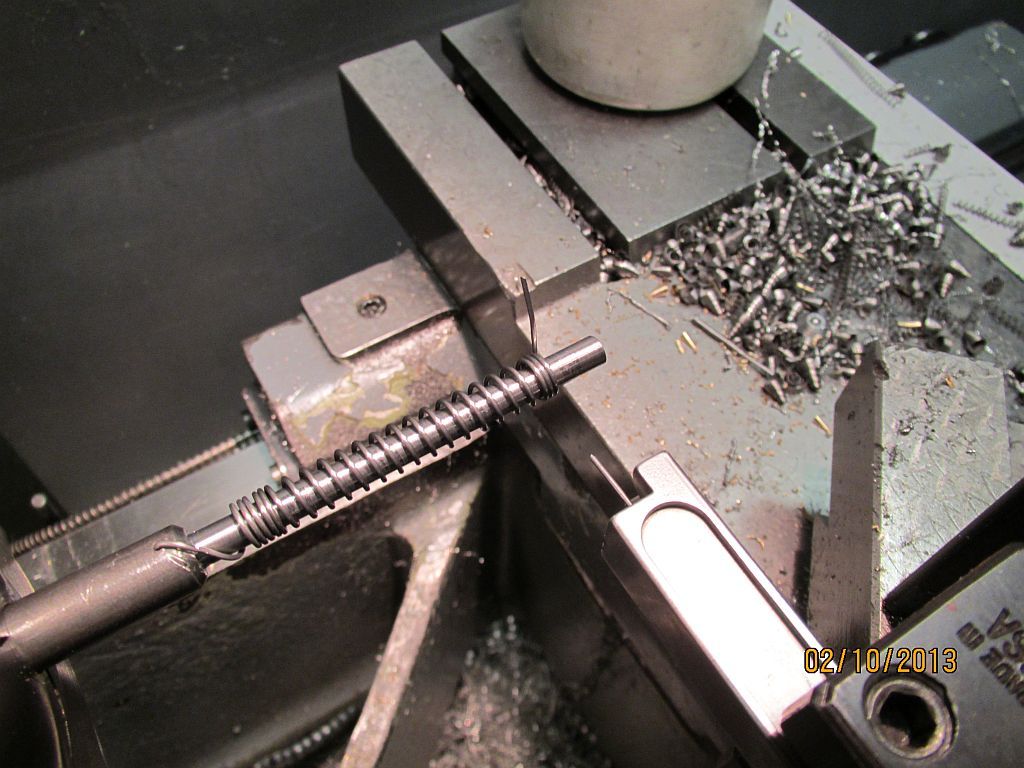
When the proper number of coils are wound the half nut is disengaged and a few tight coils are wound at the far end.

Spring_005_zps9c2cc972.jpg

Then the tension is backed off and the wire cut with some music wire nippers.

Spring_006_zps1db81287.jpg

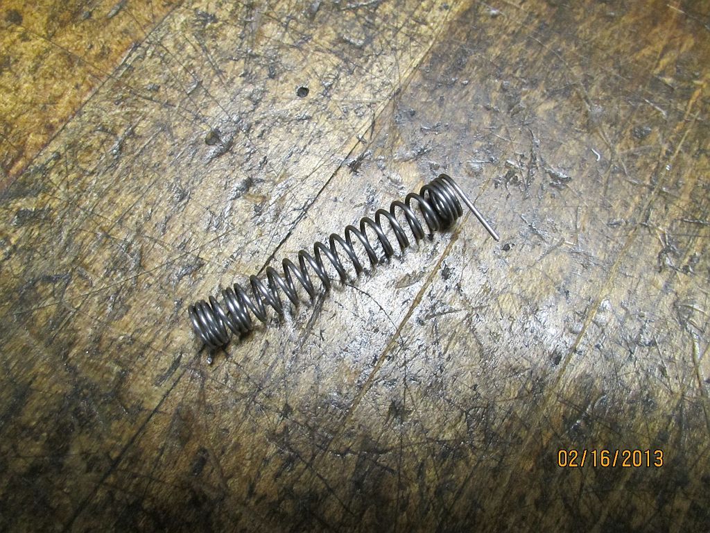
After the spring is removed from the mandrel the excess coils are cut with the nippers.

Spring_007_zpsb6fef1db.jpg

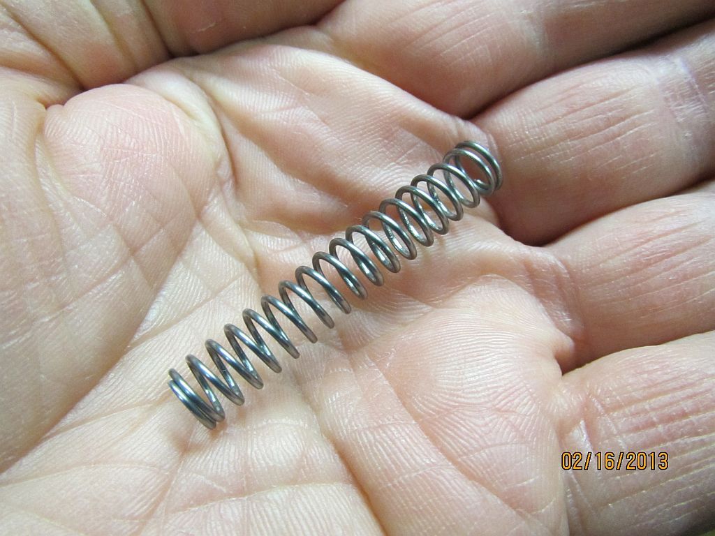
After the excess coils are removed the ends of the spring are ground flat with the belt sander.

Spring_008_zpsfcc3eaa8.jpg

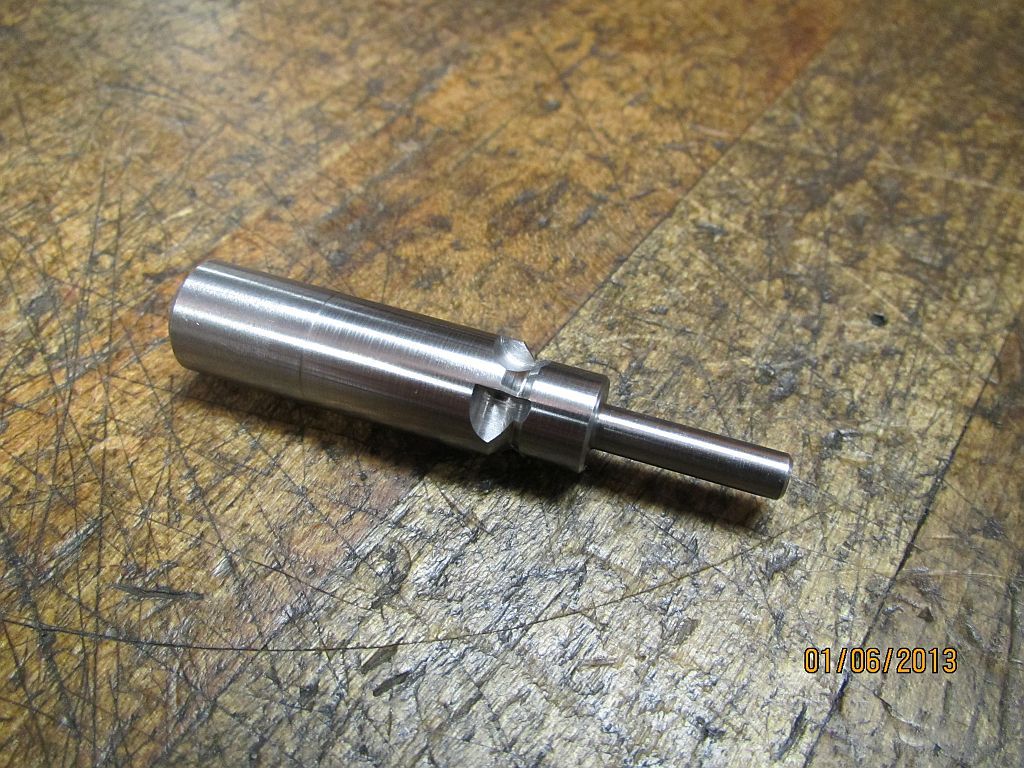
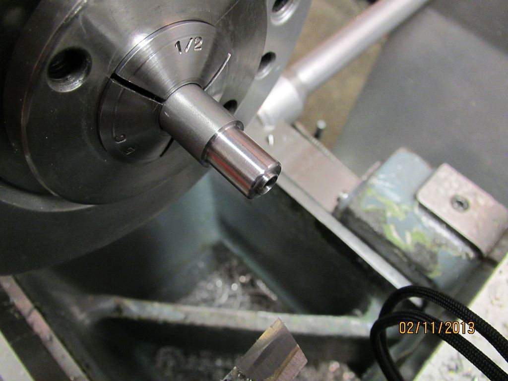
The keeper is an easy turning job. Here it is mostly roughed out; a boss was turned to fit in the inside of the spring to help keep it centered on the valve stem.

Spring_009_zps16a8eb06.jpg

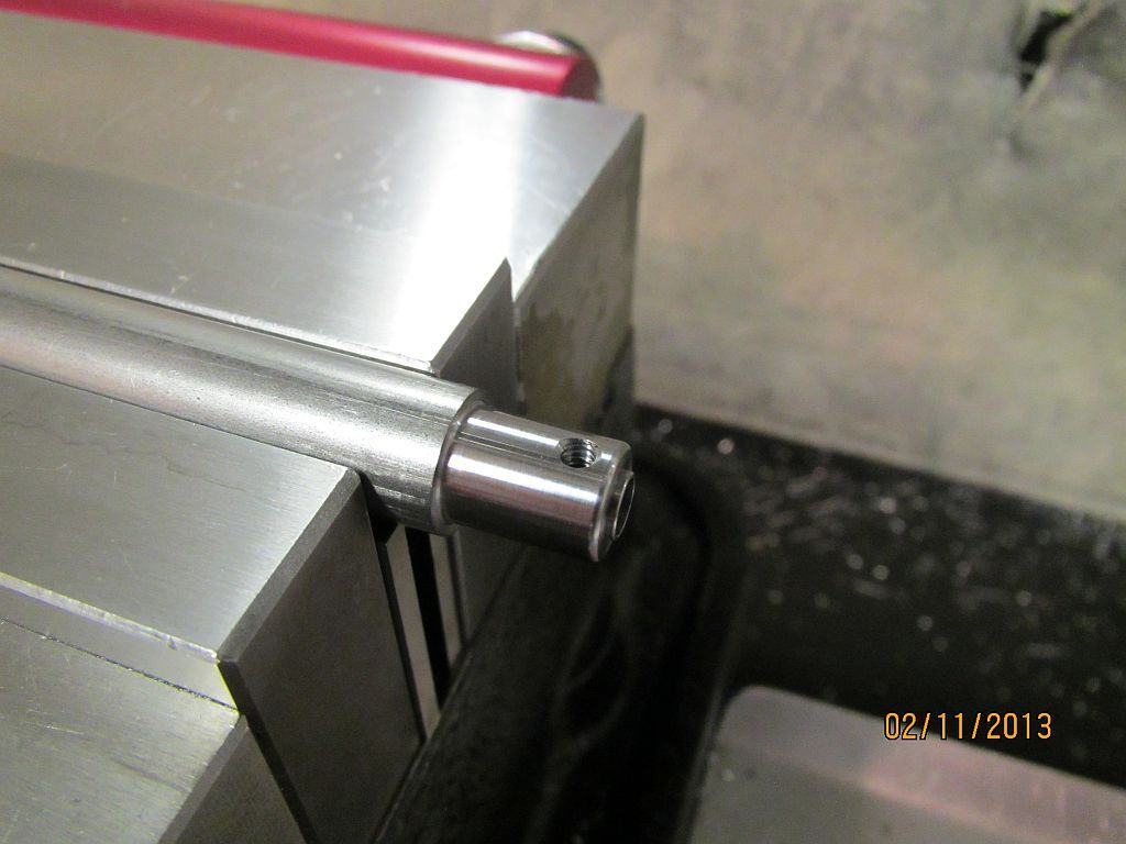
Transferred to the mill the set screw hole is located, drilled and taped.

Spring_010_zps81ae4ba6.jpg

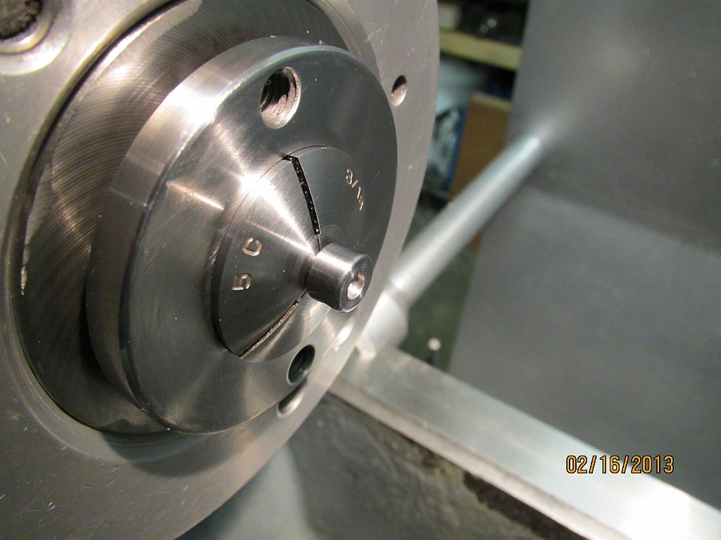
After parting it off the keeper is mounted on a 3/16” piece of stock so the bottom could be finished.

Spring_011_zps80d2c2b9.jpg

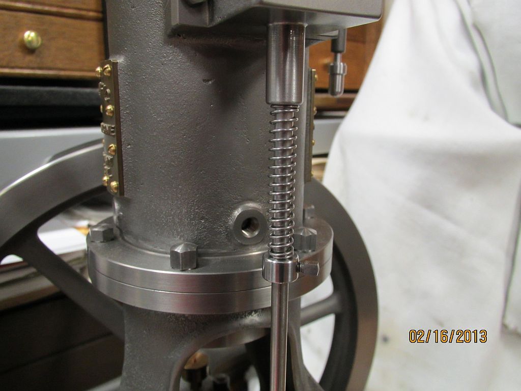
Here is the spring and keeper mounted on the engine.

Thanks for checking in,
Dave
 
Really nice Dave. Can you give us a picture and some background on the tensioner? Also, you mention "music wire nippers" are these different then regular wire cutters?

Pat
 
Really nice work on those springs. Well, really nice work on the whole project, but for some reason, those springs really impressed me. I tend to use whatever is available and just cut them off to the right length, hoping no one will look to close at them.

Valve seat cutter is also a nice piece of work. Thanks to you and George for making and showing those.

Any estimate on when you'll get to the hot tube? Kind of looking forward to seeing what that's going to look like.

Chuck
 
Really nice Dave. Can you give us a picture and some background on the tensioner? Also, you mention "music wire nippers" are these different then regular wire cutters?

Pat

Ditto that, I can see a number wheel, not much else.
Also the nipper thing. Not sure what they are, but I once blew half of the jaw off of a fairly descent quality diagonals cutting a a not very thick piece of spring wire.
Also can't not say, nice work, as usual.:)

GUS
 
I like the spring tricks! Especially putting a few extra end wraps to tidy things up. She is shaping up nicely....precision all the way..
 
Thanks guys I appreciate it,

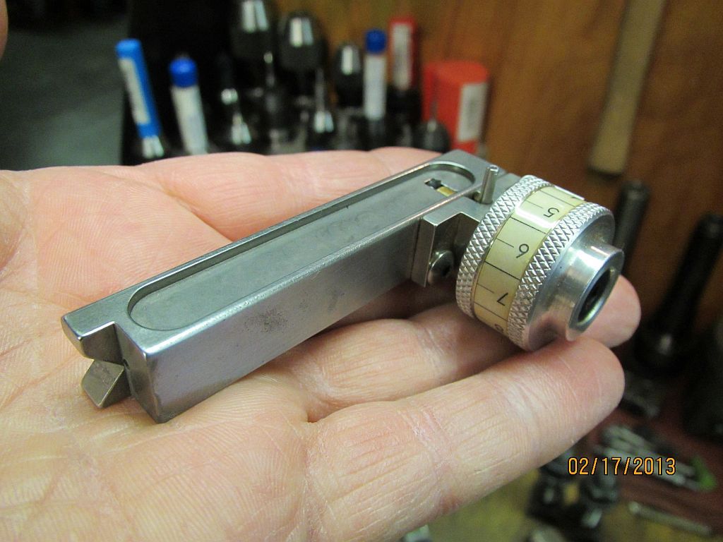
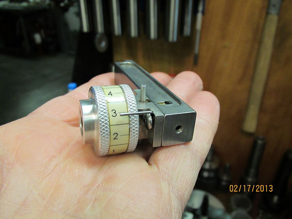
The spring wire tensioner is a handy little device I made many years ago from plans (if I remember correctly) in one of the Strictly IC Magazines. I did a quick look this evening but I couldn’t dig it up. I will keep looking to see if I can find it.

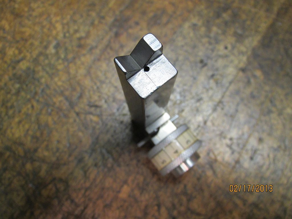
It has a couple of nice features; the vee supports the mandrel so a center isn’t needed unless you want to use one. The tension dial has number and a pointer so you can get more consistent results from spring to spring. It usually takes me a few tries or more to get an acceptable spring.

SpringWinder_002_zps860182c4.jpg

SpringWinder_001_zps286a32c1.jpg

SpringWinder_003_zpsfbc3a400.jpg


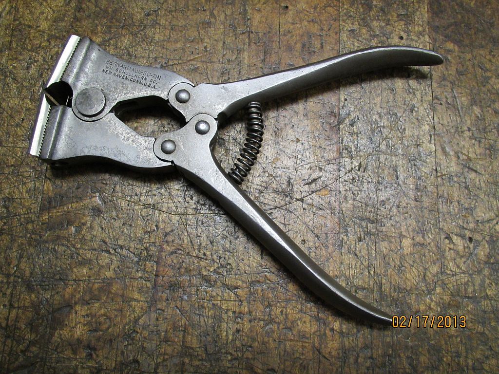
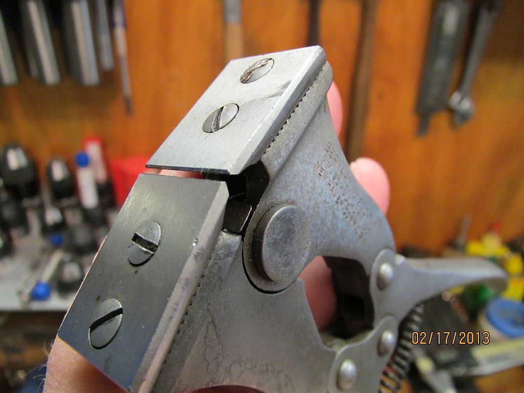
Watch eBay for the nippers; Starrett makes a real nice pair but they are pricy; I had sticker shock when went to their web site and looked them up.
They are compound leverage and have adjustable high speed steel cutting blades. The blades can be sharpened on a surface grinder.
Mine are a different brand but it wouldn’t surprise me to find out they were made by Starrett; they look just the same.
Nipper_001_zps09412ebf.jpg

Nipper_002_zpsc7a81075.jpg


Thanks again for the kind words,
Dave
 
Thanks Dave, I am especially glad to learn about the nippers before I ruined a pair of wire cutters.

Pat
 
Hi Everyone

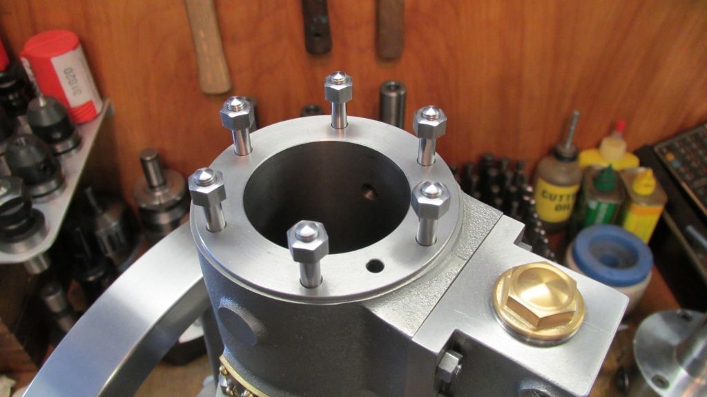
Wow it has been 3 months since my last update; where does the time go? I got real busy with a windmill rebuilding project this last winter among other things and the Pacific kind of got neglected. The only items I have got done since my last post was to finish the head studs and nuts and made a small start on the head castings.

The prints call for high crown bolts for the head but I prefer the look of studs and nuts so that is what my engine is going to have.

I have some vacation time next week after Memorial Day and I'm hoping to be able to spend some quality shop time working on the Pacific.


I have covered how I make these parts in an earlier part of the build so here I just going to show the completed parts.


And a different view


Here are the head castings; the head is made in two pieces so it will have a water jacket. The two parts will be a shrink fit. The chucking lugs have been turned and things roughed inn. The top of the head gets fully machined and polished. I’m also deviating from the plans somewhat on the water jacket design; this will keep me from having to drill and plug passages through the outer rim of the head.

Thanks for checking in,
Dave
 

Latest posts

Back
Top