Pacific Vapor Engine from Morrison & Marvin Castings

Home Model Engine Machinist Forum

Help Support Home Model Engine Machinist Forum:

This site may earn a commission from merchant affiliate links, including eBay, Amazon, and others.
You work out Come Very beautiful.
manop Thailand. I use the Language Translation are sorry
 
Hi Everyone

I had a few modifications that I wanted to do the the engine base before I started on the ignitor and intake valve chest. To facilitate casting and to have a place for the core print there was a large hole in the top of the base. This would allow the waste oil to drain down through the base and on to the skid.

The base needed to be sealed up and a proper drain put in; as far as I know this is the way the original engines were. I have seen several different locations for the drain in photos and I chose to run it out the side as seen on a Pacific/Union marine engine.

Also bosses were added for the mounting bolts as well as a boss for the intake air pipe to pass through.


Here is a shot of the base casting showing the cored hole.


A piece of ½” hot rolled steel was rescued from the scrap box .


The top side of the new oil pan is machined along with the outer profile. Then it was flipped over and milled to the desired thickness.


The base was set up in the mill and a matching pocket cut to hold the new oil pan.


The oil pan was a light tap in fit and glued in place using Loctite anaerobic gasket sealer. It was left about .01” proud and faced off after the adhesive cured.


And a shot from the bottom.


After taking a skim cut with a fly cutter it is now nice and flat.


Set up in the mill the base is counter bored for the new boss.


Using a ¼” ball end mill the oil drain is connected to the pan area.


Here the new boss has been installed and taped for the drain pipe. Also a little blending work has been done with Devcon steel filled epoxy.


The bosses were turned from cast iron bar stock.


The holes in the base were machined to accommodate the new bosses.


Then they were Loctited in place.


And finally a shot of the new air intake boss along with the new mounting bosses after a little body work with the Devcon.


Now on the to the piston trip ignitor,
Thanks for checking in.
Dave
 
Hi Dave,
Every time I tune in here I am always amazed at the quality of your work and the attention to detail as well as the machining set ups and methods.
Well done. Thanks for letting us watch and learn.

GUS
 
Thanks for stopping by Gus, and also for your comments,

Dave
 
Hi everyone

I was able to spend some time late last month and got the engraving done on the Lunkenheimer grease cups. Armed with a new spring-loaded diamond engraver from 2L and some encouragement from Gary Hart, I gave it a try.

The geometry was created in Solid Works using a photo of the original as a drawing template; then on to the CAM program to create the tool path.

After a few test cuts I had the feed and speed pretty well dialed in; I’m pleased how good they came out. Because the diamond displaces the material instead of cutting it the bumps needed to be carefully sanded off.

The letters are approximately .03” tall and ended up being about .005” deep.

Here are a few pictures, one showing the original I used as a pattern.


This was a fun little task and I already have an idea where I will use it next.

Thanks for checking in,
Dave
 
The base bosses are a neat feature/trick I must file away for future use. The Lunkenheimer miniatures are a sweet finishing touch. Thanks a bunch for the posts and the top shelf craftsmanship.
 
Thanks for checking in Myrickman,

I appreciate the kind words.

Dave
 
Hi Everyone

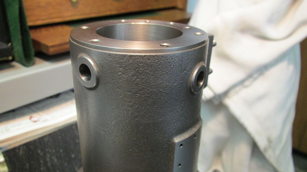
I finally was able to carve out some time to work on the piston trip ignitor. The cylinder casting had bosses cast for the feed throughs; but the way my cylinder finished up I wasn’t completely happy with the position of the boss relative to where the holes should be.

My original plan was to completely remove the boss and counter bore the cylinder to create a flat area for the insulator to sit. I actually did this but then wasn’t overly happy with the way it looked. Part of the reason was I sized the counter bore to fit some mica washers I had on hand; and after the fact the scale just wasn’t correct. So after thinking about it for a few days I decided to go ahead and replace the bosses.

The new bosses were turned and then pressed and Loctited into the counter bore. A small fillet was added with the Devcon and I was starting to feel better about how it was all looking. I have seen these engines both ways (with the counter bore and also with the boss) so I would say either way could be correct.

The Devcon I have been using is called Plastic Steel Putty (A) it is a steel reinforced epoxy; the mix ratio is 9:1 by weight or 2.5:1 by volume. This gives you some idea of the amount of steel filler that it has in it. It is not cheap but a much better product than JB Weld types of epoxies.


Here are the two new ignitor bosses.


And a close-up shot.


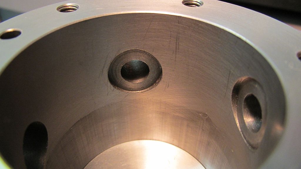
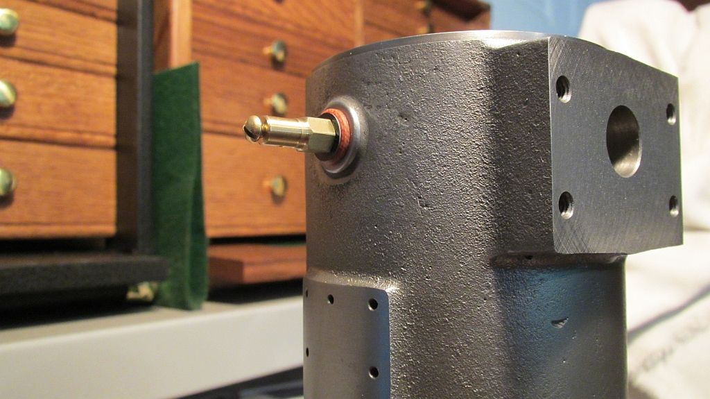
I decided to counter bore the inside of the cylinder for the mica to sit in; as far as I know this is also how the original engine was done. I modified a standard counter bore (cut off) so it would fit in the cylinder bore.


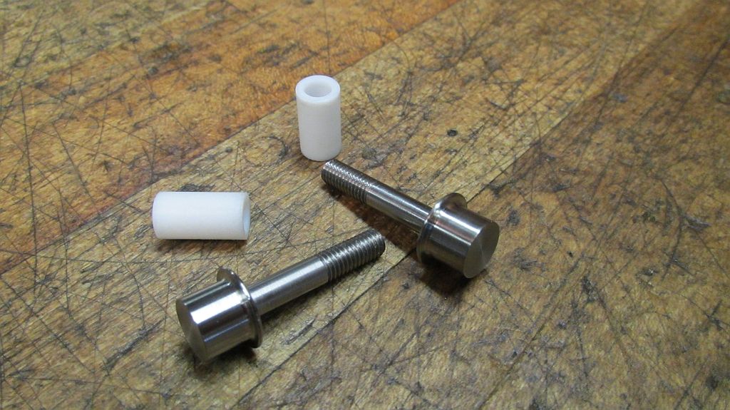
Teflon insulator bushings were turned along with the start of the feed throughs; the feed throughs were made form 303 stainless steel.


The feed through is milled half way to form the clamp area for the blade.


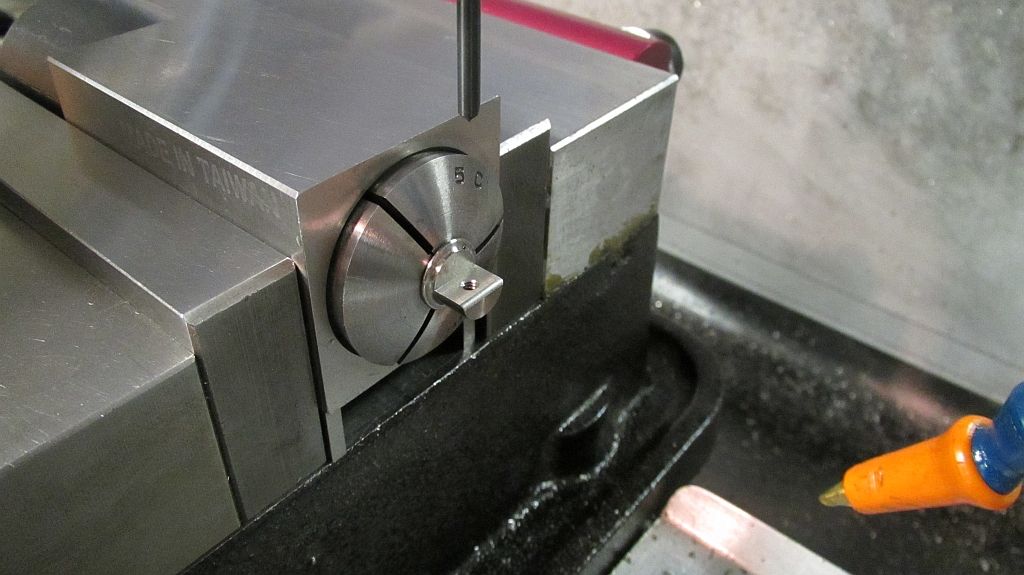
Then drilled and tapped; also the edge is given a small radius to remove a stress point from the balde.


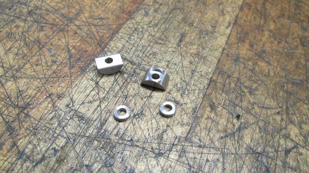
The clamp blocks are machined and counter bored to accept a boss for the clamp screw.


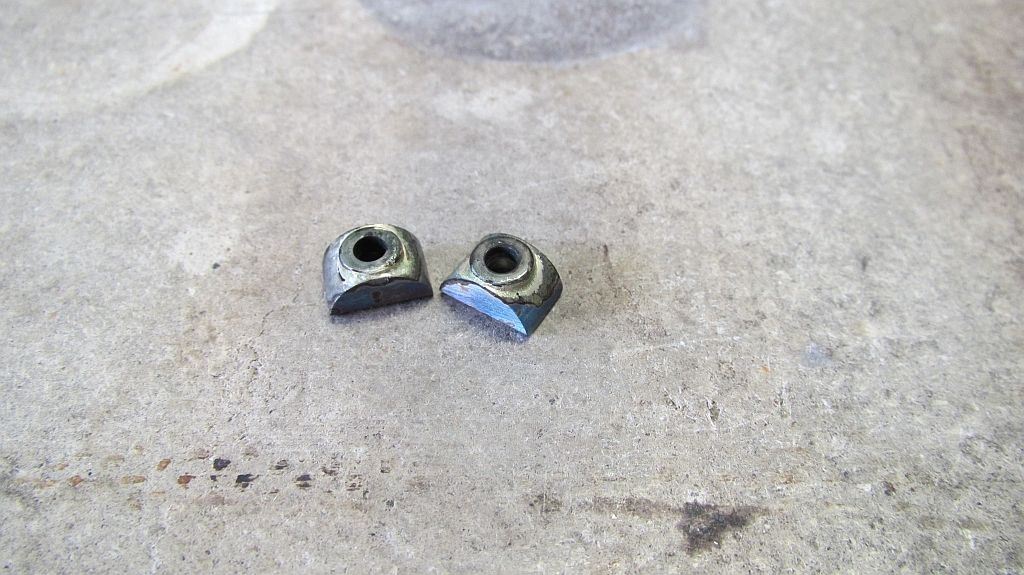
The bosses are silver soldered in place.


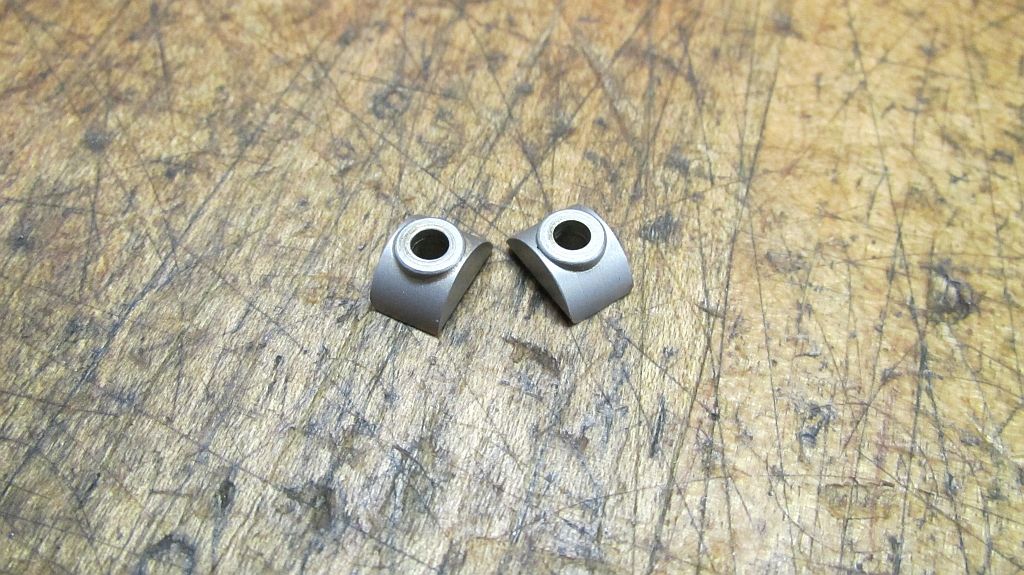
Here they are after cleaning and a trip through the blast cabinet.


The blades are machined out of a commercial air compressor valve spring; the spring just happened to be the right thickness. The stock is screwed to a chucking piece and the clamps removed.


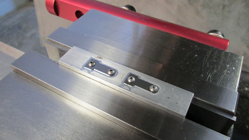
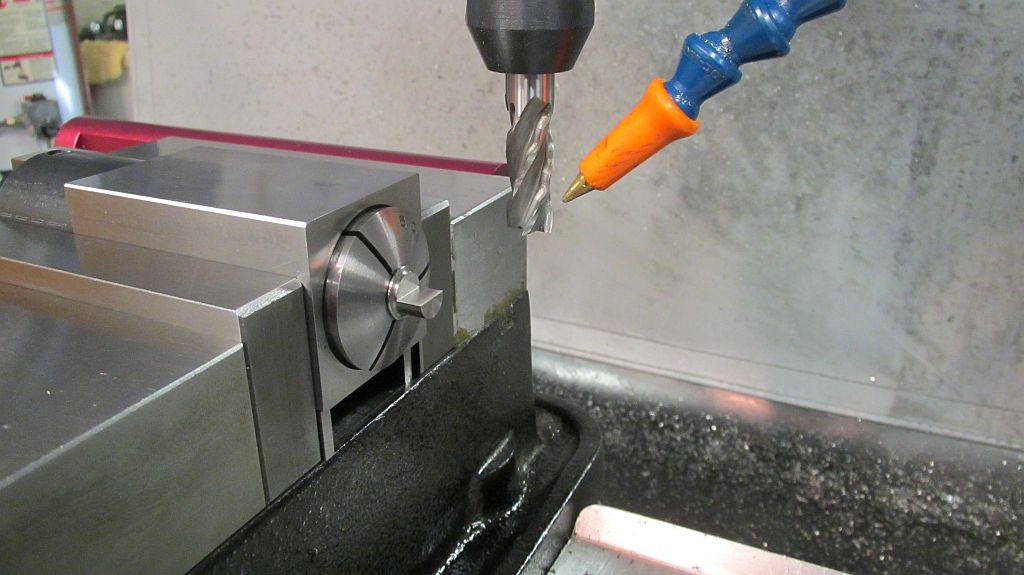
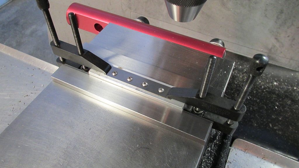
The blades are profiled using a small carbide end mill.


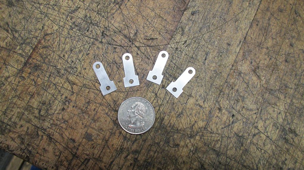
Here they are ready for the points to be installed; also made a couple of spares while I was set up and going.


The points were machined out of meteor metal that I purchased from one of the magneto guys a number of years ago. I think that it is high in Nickel but not sure what else is in it. I plan to take a sample to work and have one of the guys in the lab check it out.

I may also try German silver point material as this is what one of the gas engine suppliers is selling for Ignitor point replacements in the full sized antique engines

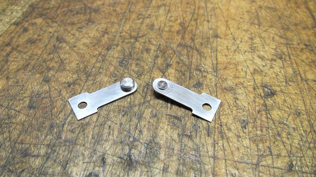
The points were swaged in place after machining.

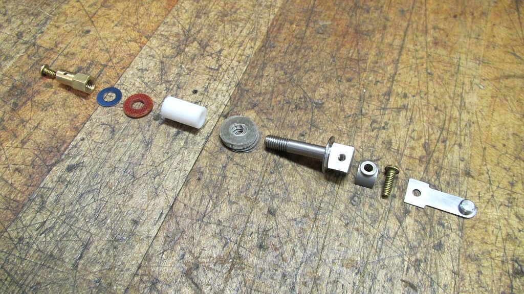
Here is the lineup of all the parts for one feed through assembly. The mica washers are added or removed to properly align the points. The outside insulator is made from linen phenolic followed by a thin washer punched from some blue spring steel and then the brass nut/ wire clamp.


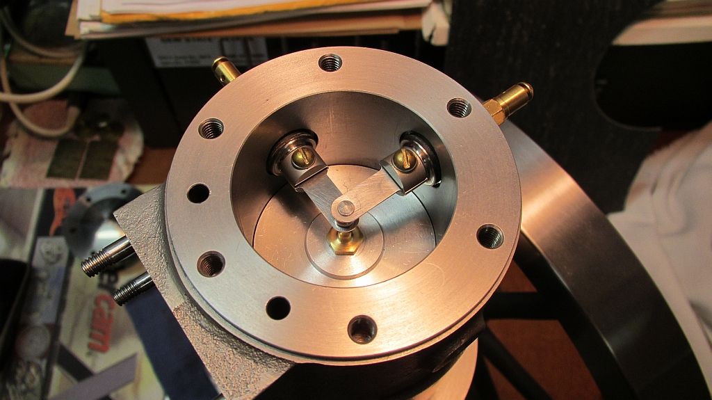
Here are all the parts installed in the cylinder; notice the brass button screwed into the top of the piston.


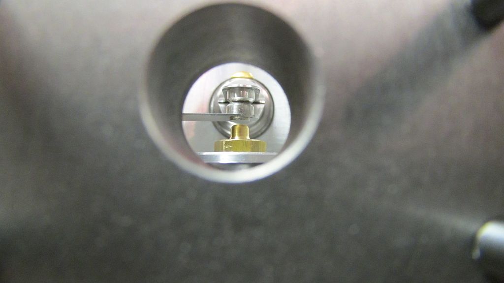
Here is a shot through the exhaust port; the button on the piston closes the points on the way up and then the point open as the piston starts back down.

Because room is tight all fine adjustments will be made using shims; either under the trip button or under the blades. I lengthened my connecting rod to increase the compression ratio so there is not enough room for the stud and jam nut that would have originally been used on the top of the piston.


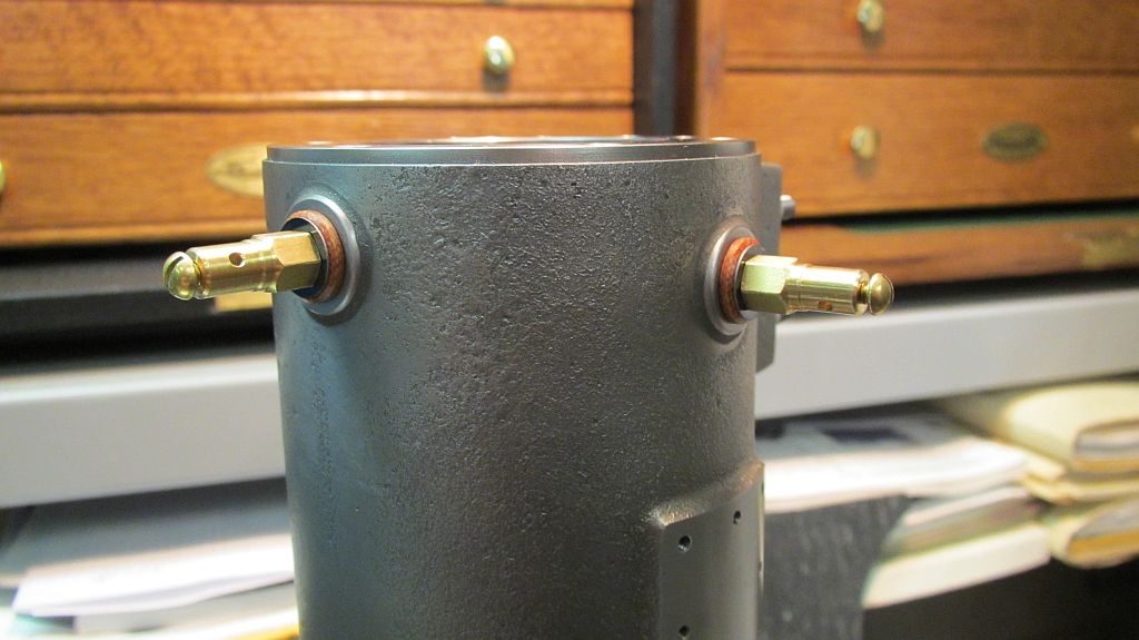
Here are a couple shots of the outside parts.


The major problem with this system is there is no spark advance; the engine will always runs in a retarded condition. It was 1890 after all and this engine represents some of the very early US engine development.


Thanks for checking in.
Dave
 
Last edited:
Thanks for checking in Dave.

I appreciate the comments.

Dave
 
Dave,

Amazing work, you're a true craftsman. I'm extremely impressed.
 
Hi everyone

I have been struggling trying to get an update posted on the Pacific; I haven’t been able to make much progress lately but hopefully that will change.

The next part on the engine is the intake valve assembly; there isn’t anything in the way of plans or a casting for this part. Only some guidelines form Lester Bowman on the prints of what he did on his model.

Some of the guys that have built this engine use a modified check valve for the intake valve chest with good results.

Roland Morrison (Morrison & Marvin) supplies a nice set of lost wax castings for the fuel and air cocks that are designed for 1/6” pipe and are a real nice fit on the Pacific.

Using the size of the hand valves to go by and looking at photos and drawings of the original engines I designed an intake valve assembly that I feel complements the hand valves and fits the scale of the engine nicely.

This valve could have been made as a built up assembly but I chose to carve it from solid stock using CNC.


Here is my Alibre (Geomagic) assembly drawing of the valve.


Starting out the first side is roughed out.


Here the finish tool path is running on the first side of the valve body.


The first side finished.


The block is flipped over and the second side roughed out.


After finishing the second side the valve body is ready for some secondary machining operations.
More to follow.

Thanks for checking in.
Dave
 
Hi Dave,

Beautiful work as usual - that's some really tidy 3D work you've done there. I'm quite envious - it looks as though your mill has a much bigger program memory than mine does to get that sort of finish. What sort of mill and CAM system are you using?

Dave
 
Thanks Dave!

I have been doing the 3 axis work on my mill at work; it is a 22"X16" Fadal and I use Master CAM X5 for programming. I'm lucky that the small shop (R&D Model Shop) that I work in, we all have our own dedicated machines. My work station is right at my machine so it is no problem to DNC large programs.

Solid Works and Master CAM at work and Geo-magic (Alibre) and Bob CAD at home.

I'm not thrilled about the faceting; but with a quick rub with some fine sand paper it disappears quickly.

Thanks again for the comments,
Dave
 
Ah, now I'm jealous! I share an Interact, but for some reason, and I've not had it happen before, I just can't get DNC to work on this one so it really limits the finishes possible. What sort of field does your model shop work in?

Have you been modelling much of your Pacific in SW? I do like to take 2D plans into SW, as it's a great way of spotting drawing errors or conflicts before they get to the metal (not that it always works!!)
 
Absolutely magnificent work, would love to have a CNC mill, ran one at work for some time but it was mostly 2.5D.

Paul.
 
Hi Dave

We work in the imaging and printing business; it's not a small company I'm sure you have heard of it.;)

We have one Interact in the shop and I know not log ago they needed to run a large program on it; I think what they ended up doing to make it work was so set the baud rate down to 600 both at the the machine and the terminal program. After that it was working fine; the terminal/editor program we use in CIMCO Edit.

Paul, thanks for the kind words and checking in on my project.

Dave
 
Hi Everyone

Here is the continuation of the intake valve construction.
The valve body was removed from the frame using the band saw; I’m sorry I got carried away and didn’t take many machining pictures. It was all pretty straight forward; I decided instead of reaching down through the 1/16” pipe openings to cut the ports that I would make an insert that would have the ports, valve seat and threads for the cap. My buddy gave me a bad time about it but it all worked out well.


After some machine work and fettling here is the valve body ready to have the insert installed.


Here is a shot of the insert; you can see the ports and the valve seat on the edge of the flat land.


And a different view.


The insert was Loctited in place with high strength cylindrical bonder (609) also I always use the primer.


After the Loctite set the top of the insert was faced off flush with the bronze body.


Here is a shot of the valve; the original had the tapered top like this one does (at least the one I saw a photo of did).


The two remaining parts were the cap and the bob weight. The cap was designed to look like the one on the exhaust chest only smaller.


Here is a shot of the cap installed on the body.


And finally a couple shot of the completed valve assembly installed on the engine.


I’m very pleased with how it turned out; hopefully it will perform ok as well.

I still need to make the copper sealing washers for both valves.

Now on to the gas and air hand cocks.


Thanks again for checking in and the comments.
Dave
 

Latest posts

Back
Top