Opposed Twin I.C.

Home Model Engine Machinist Forum

Help Support Home Model Engine Machinist Forum:

This site may earn a commission from merchant affiliate links, including eBay, Amazon, and others.
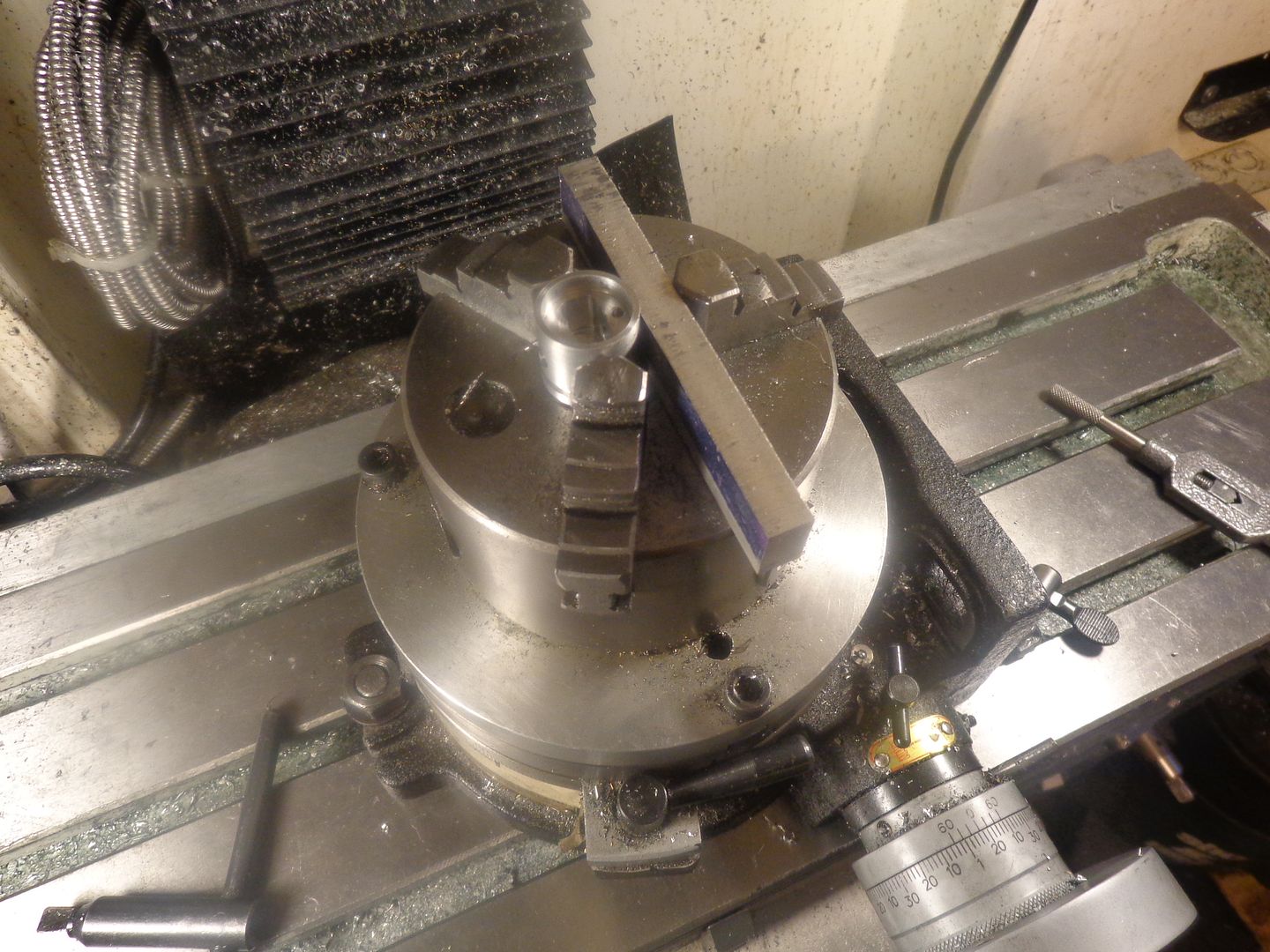
The pistons finished up nicely. One of the issues I always have when making pistons, is how to put the wrist pin hole in and be perfectly sure it is at 90 degrees to the counterbored slot for the con-rod, and at perfect right angles to the central axis of the piston. I was given this tip some time ago, but never got to try it until yesterday.--The secret---set up in the rotary table chuck, on the mill bed, as shown here. Align the chuck jaws as shown, and put a "sacrificial" spacer between the side of the piston and the right hand jaw. My rotary table is "keyed" to the tee- slots in the top of my milling machine bed, so I am sure of it's position when it is bolted to the Tee slots. Make the slot which the con-rod fits into runs between you and the mill column (the Z axis).--Remember now, you have the rotary table locked in position---we are not going to rotate the attached chuck. Once the slot is finished to size, undo the bolts which hold the rotary table to the tee slots and turn the rotary table with chuck attached (still gripping the piston) 90 degrees to the right so the centerline of the piston is parallel to the milling machine bed. Use a square to make sure the rotary table is setting 90 degrees to the milling machine bed and bolt it down to the tee slots again. Use your center finding device (whatever it may be) to find the centerline of the piston, zero your tool on the exposed end of the piston skirt, and move the table in the right to left (X-travel) to position the chuck directly above the position you want the wrist pin hole to be. Now you have the chuck jaws positioned so that you can run the drill down between them from the top with no interference, and you can drill (and ream) right on through the far side of the piston into the sacrificial aluminum spacer. This ensures that the wrist pin hole will be "square and true" to all the other surfaces. If you are following this thread, please say Hi and let me know you are interested. I am about to embark on a pair of connecting rods.---Brian
 
I'm following along and enjoying Brian. Your builds are always chock full of helpful insights and your engines are awesome. I'm really curious as to what this one will sound like and I'm guessing it won't be long now til I find out.
 
Guys--Thank you all so much for saying Hi!!! I think it's time to go to bed now. Before supper I KNOW that I laid out and cut out and drilled the inside radius holes in two connecting rods. I KNOW that I sat one down while I milled out the profile on the other one. I eat supper, and came back down to my shop. I wanted to take a picture of the two stages of con-rod profiling. The damned thing that I hadn't started to profile is GONE. I put away all my tools.--I cleaned up all the mess. I've walked out to the bandsaw and looked four times. I'm hoping that if I can get a good nights sleep, that whatever snuck in and stole my friggin' connecting rod will sneak in again and put it back!!!---Brian
 
Those little gremlins that steal our parts and tools sure are a pain!
anybody know of any good spray to get rid of them??? :wall:
 
Magnet on a stick before you sweep.. Unless they are non magnetic, then they are just gone.
 
Went to bed and thought for a while. Then I remembered I has set the second one up on a ventilating rad to dry a coating of layout dye.
 
It's so frustrating when you loose a part or tool you literally just had in your hand. Seems to happen on a regular basis to me!

The engine is looking fantastic Brian.
 
We've got sparkplugs!! We've got sparkplug wires and boots!! And we've made a good start on connecting rods and caps. I have one more con-rod cap to make, and then I can start profiling the sides of the con-rod and put in the big end bores. There is a lot of work in these connecting rods.
 
I'm very pleased with the way these connecting rods turned out. They are a full 3/8" thick at the big end boss, the rest of the rod is faced .033" on each side, to clear the sides of the crankshaft journal support arms and to fit into the 5/16" slot in the pistons. Also attached you will see the simple jig I came up with to machine them that way.

 
There are three classifications of assembly fit. Tight, Real tight, and "Oh my Gawd!!" tight. I'm sure that this fits into the third category. The good news is that everything fits, and goes round and round and up and down with no interferences. While I had the cylinders off, I lapped the pistons into the cylinders with 600 grit paste and a long "handle" purpose made for this job. I'm not sure this step is really necessary, but it knocks down any high spots on the pistons and gives a very nice sliding fit.--The pistons will slide slowly down a cylinder stood on end, but stop if I put my thumb over the bottom end of the cylinder to stop air coming out.--and this is dry, without any oil or piston rings. That big ugly collar on the camshaft is just that--a big ugly collar, to keep the camshaft and gear from sliding out of the block.--an added benefit is that the collar is the same o.d. as the maximum outer diameters of the cams will be, and the crankshaft clears it. Big sigh of relief. If there are going to be any major crashes, this is the point at which they show up, and all seems to be clear.
 
So, here we have the engine mocked up into position, with the "Finger chopping flywheel from Hell" setting in place on the crankshaft. The cooling air provided by the vanes on the flywheel will blow directly onto the cylinders and heads. The metal "shroud" around the flywheel is stationary, and does not rotate. It will be bolted to the base. If I feel exceptionally wimpy when I go to actually run this thing, I may put a metal mesh between the flywheel and the engine, but Hey---Think of all the guys out there who are running airplane propellers on their engines with no guarding of any kind on them!! I can't really do much more today, as I need to buy material tomorrow to make the base risers with.
 
A few years ago (10 or 12) when I built my last hot-rod, I come into possession of a radio speaker grill from some old car. It was an aftermarket kind of thing, but the pattern and shape of the openings in the metal cover was so beautiful that I decided I would keep it, in case I ever wanted a piece of "safety grill" for an application like this. I have just finished a thorough search of all my cupboards, and I can't find it anywhere. I will have another look tomorrow, because it would be perfect to cover the near side of the flywheel/fan shroud.
 
I was afraid that my brazing skills might have left me. It's been about 30 years since I did any serious brazing. I went down to the welding supply shop this morning and bought a stick of 3/32" flux coated brazing rod. What do you know---I can still braze as good as I could in 1985!!! This is going to make my fingers a lot happier when I run this engine. I haven't made the mounting brackets yet, nor the guarding on the far side of the flywheel/fan, but I like this.
 
Thanks Hussien---It looks like we are going to get a bunch of your fellow countrymen here in Canada in the very near future. I'll say Hi for you.---Brian
 
Thank you brian.
Damn for terrorist who resolve Us.
I follow up most of your designs and I hope that i can make engine one day.
:):):):):)
 
The fan shroud/guard is finished, painted, and installed. I think it adds to the overall engine, and there is definitely a much greater safety factor now. I like that satin finish black paint for jobs like this. It doesn't show up every small imperfection in the painted metal, but it does really make the brass and aluminum "pop" by contrast.---Brian


Latest posts

Back
Top