You are using an out of date browser. It may not display this or other websites correctly.
You should upgrade or use an alternative browser.
You should upgrade or use an alternative browser.
Opposed Twin I.C.
- Thread starter Brian Rupnow
- Start date

Help Support Home Model Engine Machinist Forum:
This site may earn a commission from merchant affiliate
links, including eBay, Amazon, and others.
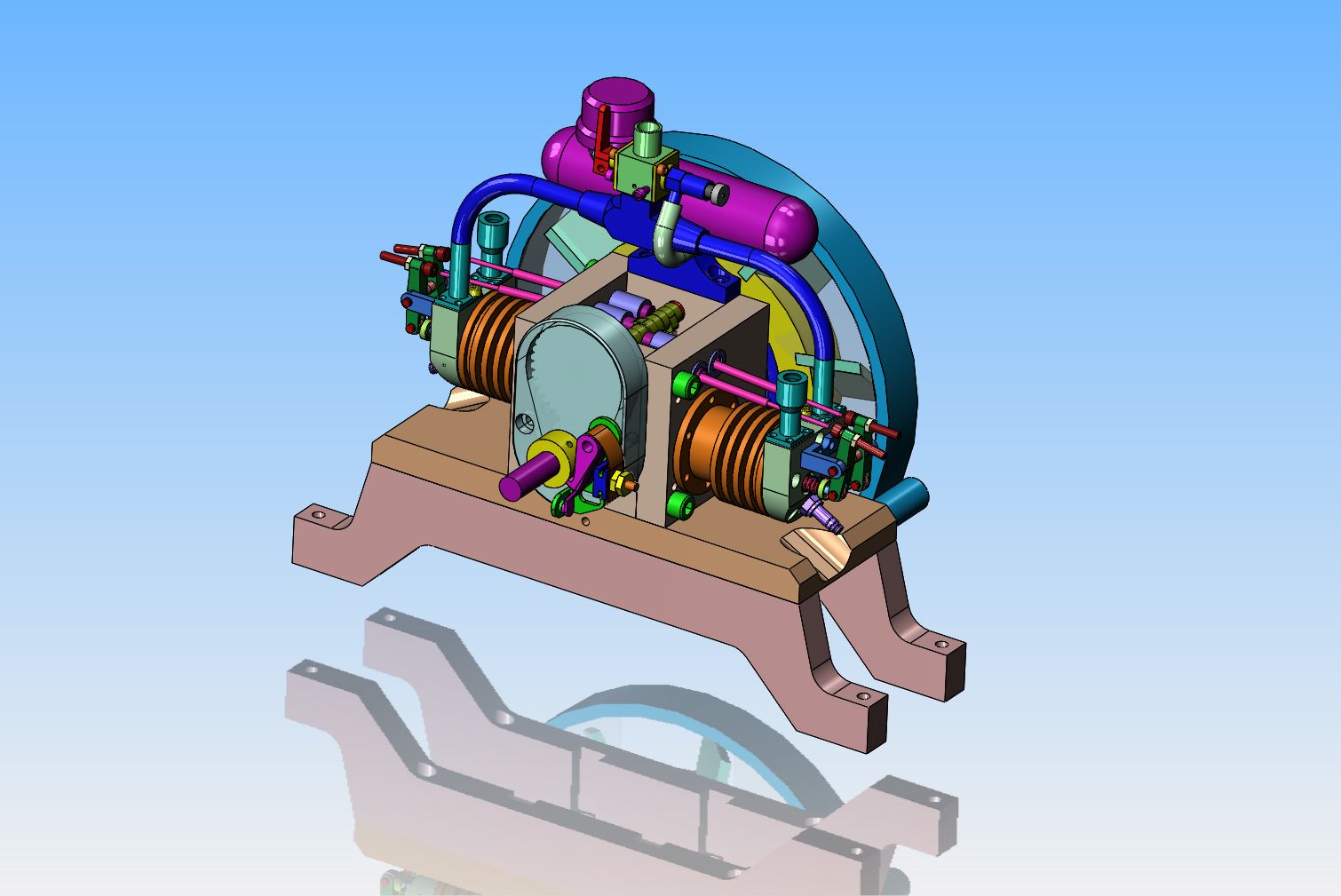
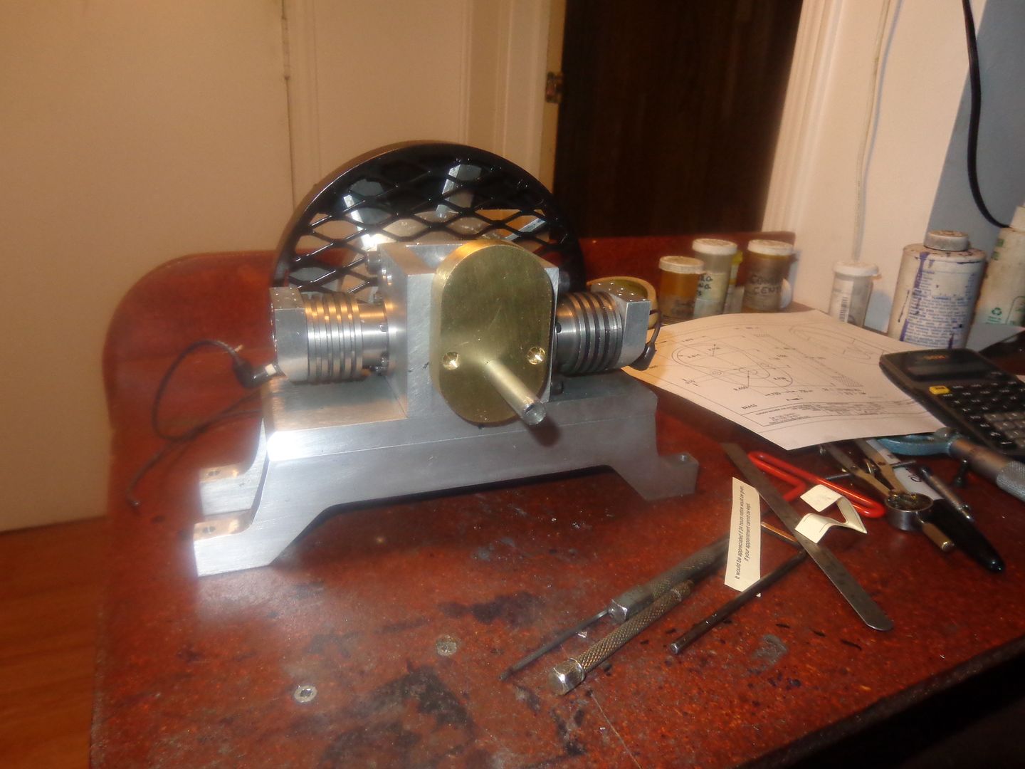
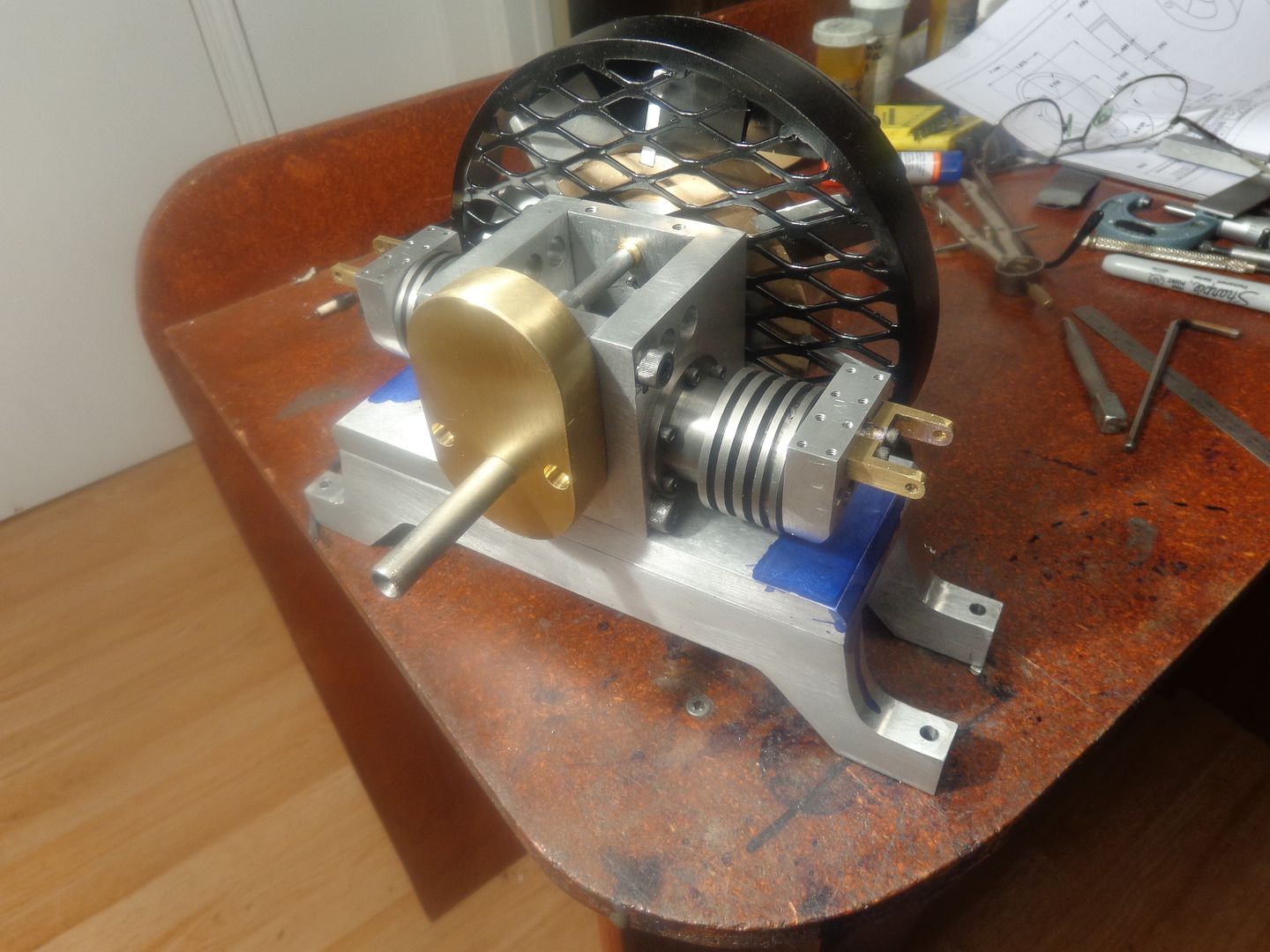
The gearcase is finished except for polishing. With the heads on and sparkplugs in place, I can see that the plug boot sets quite close to the base. I don't know if this is going to give me a problem or not. I won't really know until I actually run the engine if the plug wires are going to short out to the base. If they do, there is lots of "free space" under each cylinder to machine the base away, although that's not something I really want to do.

- Joined
- May 27, 2010
- Messages
- 2,999
- Reaction score
- 1,171
Gear case looks good and expensive.
Its Christmas Eve here and hot and humid and rainy.
Merry Christmas!!!!
Its Christmas Eve here and hot and humid and rainy.
Merry Christmas!!!!
Last edited:
Today I finished the rocker arm support brackets. As you can see, I have layout dye on the base--I figure it is much easier to cut away some material to prevent the danger of ignition sparks arcing to the base at this stage of the game instead of waiting until later when all the parts are added. I am rapidly getting down to the "fiddly bits" of this build. Building an engine like this is a lot like eating an elephant.--If you look at the overall scope of how many parts there are, it's pretty daunting. If you just settle in and eat one bite at a time, it gets done eventually. Hope you all have a Merry Christmas and a Happy New Year. I have to go help grandma now, to get the house ready for an onslaught of children and grandchildren coming tomorrow.---Brian

Longboy
Well-Known Member
Brass is class. Looks nice dominating the front of the frame.
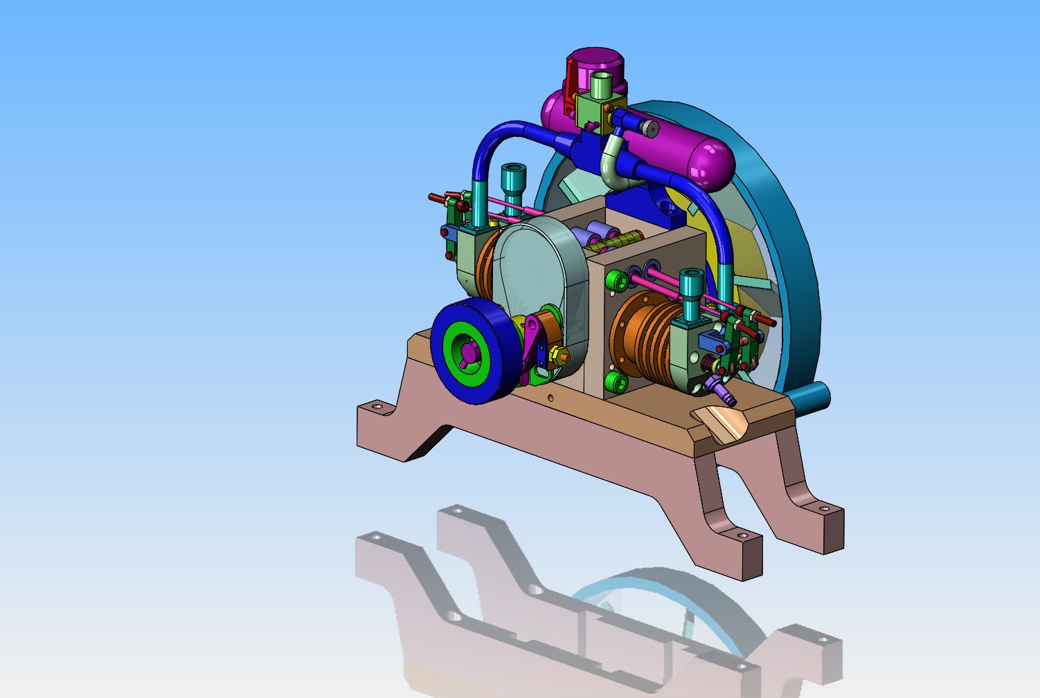
I am at the stage of this build now where I need something on the front of the engine which I can grip in my hand to turn the engine over with. I also need a receiver hub for the starter spud which I use in my variable speed drill to start the engine with. I used a similar set-up on my dual opposed piston engine and was satisfied with the way it turned out, so I will use the same set-up here.

Last edited:
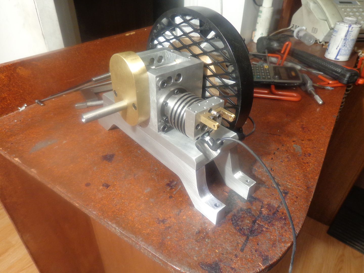
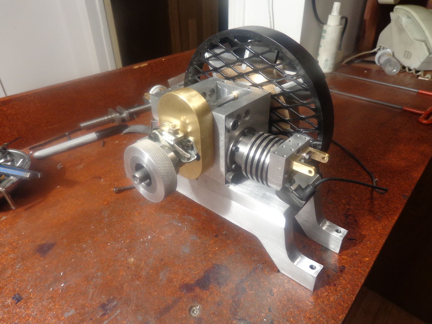
Today I machined the ignition cam, and installed it and the ignition points. I also made up a knurled handwheel to let me turn the engine over by hand. This knurled handwheel also has the center configured to take the "starter spud" which fits into my variable speed drill for starting the engine. I have not yet trimmed the crankshaft to length. After it is trimmed and the countersunk ends cut off, the end of the crankshaft will be more or less flush with the face of the handwheel.

ZebDog
Well-Known Member
hi Brian
I been reading your build on this engine from the stat great work
looking forward to the day she fires up for the first time
Steve
I been reading your build on this engine from the stat great work
looking forward to the day she fires up for the first time
Steve
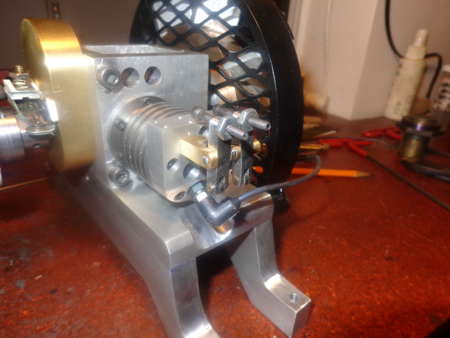
If you are ever talking to anyone about model engines, and the subject of "Rocker arms" should come up in the same conversation as the words "easy" or " Nothing to it." I sincerely urge you to smack them up side of the head, and say "Brian told me to do that!!!!" Damn, there's a lot of work in four rocker arms!!!!



Last edited:
The four valve lifter guides are made from 01 drill rod, then heated cherry red and quenched in a cup of oil. They are Loctited into holes in the block. I don't like to even think about press fitting things like this, because if you don't have a heat treat oven to reheat and "draw them back" a little in hardness, they are quite brittle and will shatter like glass. (Don't ask me how I know.) I had to make five of these to get four.--On the very first one I made, I turned the outer diameter .005" under .375. Surprisingly, my new lathe is just as happy to turn things undersized as my old one was!!! Now I have to go and shovel my front steps and walk, as we have our first real snowfall of the year.
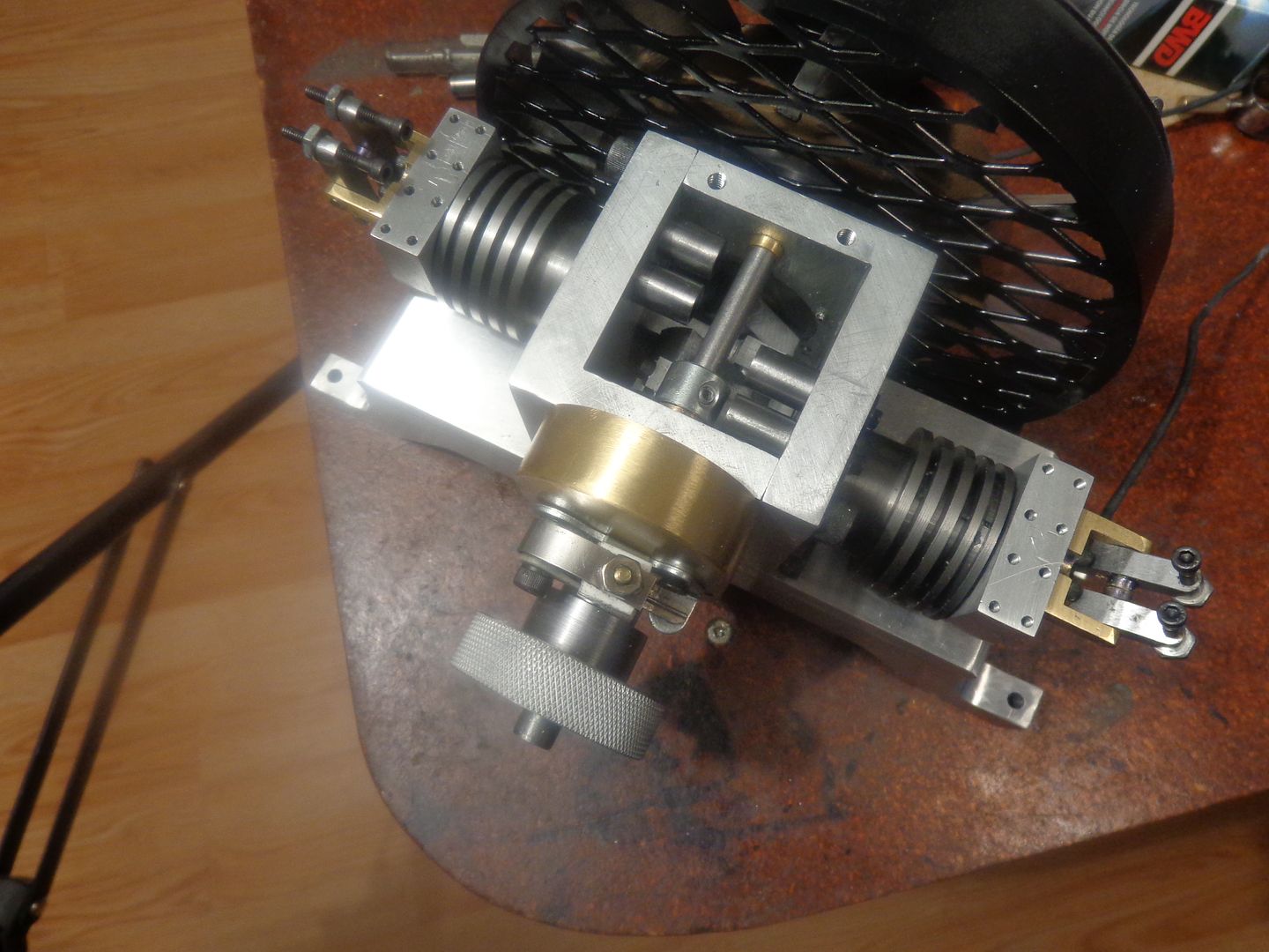

Last edited:
You don't need anything sophisticated for a temper accurate enough for our work. You can use a small flame and go by the colour, or, for parts like your tappet guides, putting them in a domestic oven at 200C (~400F) will make them a good deal tougher without loosing hardness.
You have to look really hard to see this, but the valve lifters are finished and installed in their guides. they also are made from O1 steel, flame hardened and quenched. I have shown them extended far beyond where they would normally set. When the cams are installed, they will ride right up against the cam lobes and very little will show above the outer lip of the valve lifter guides. These lifters have a counterbored pocket in the outer ends, which the push-rods for the valves will set into.
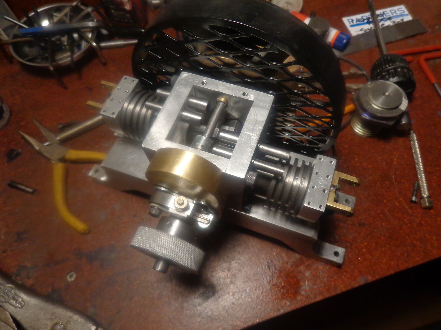

It's hard to believe, but I'm starting to run out of things to make on this engine. I was going to make the valve cages tomorrow, but the company where I buy my valve springs won't be open until Monday, and I don't want to make the cages until I am absolutely sure of the inside diameter of the valve springs I will be using. Same goes for the valve keeper plates. I still have to make cams, but that's a whole different story. I was never able to get the original Jaguar engine using the cams designed by Malcolm Stride to work right without blowing vapour back thru the carburetor intake. I don't really think there was a problem with his design nor with my fabrication. Several people who built his Bobcat, which was a two cylinder version of the Jaguar didn't experience the same vapour problem. I am pretty sure that his cam design was for a high revving engine with considerable overlap in the valve train, and I am looking for a slower more industrial style cam , so I'm kind of saving the cams for the "last thing". I can probably build the valves tomorrow, and start thinking about intake manifold runners and exhaust pipes.
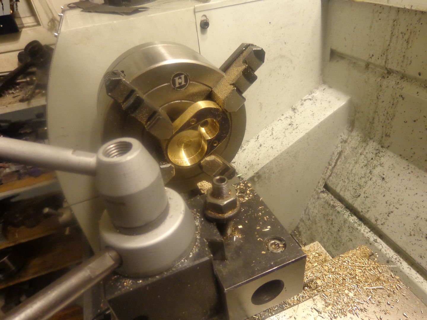
Today was valve making day. Not a terribly difficult job, but time consuming. I do not turn my valves between centers. I hold the parent rod in my 3 jaw lathe chuck, and turn the maximum diameter (in this case .312") to size first. Then I turn down 1/3 of the stem length to within about +.002 to +.004 from finished size. Doing it this way minimizes the deflection that I would get if I tried to turn the full length down to .125". The brass piece in the picture is a remnant from a gear that was left over from another job. I drilled and reamed a 0.125" hole thru the center of it before I started turning the valves. After the entire valve stem length was turned to just a bit oversize, I then used 220 grit emery cloth to bring it down to final size. Of course, this means many stops to try the brass piece on to see when it will slide nicely over the valve stem. This "sanding" procedure brings the stem down to exact size, and removes 90% of the machining marks on the stem. I machined the stems with my lathe topslide flipped around to the rear side of the lathe and set at 45 degrees and locked--This way, when the stem was finished I could unlock the topslide and use it to advance the tool to put the 45 degree bevel on the face of the valve. I left about 3" of the parent metal attached to the lathe, as this will give me a "handle" to hold when I lap the valves into the valve seats with 400, then 600 grit lapping paste. After that is finished, I will cut the "handle" portion off and be left with only the valve.
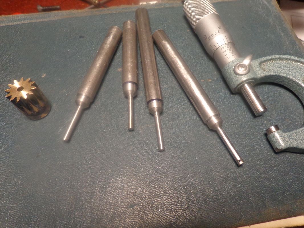

-I am not overly impressed with the finish on the 45 degree face, but that is because my new lathe doesn't turn as fast at it's top speed as my old lathe did. (Without getting into the work of changing the v-belt drive from low range into high range.) I'm not sure it really matters, as the machining marks on the face are annular grooves and will probably come out after the lapping process. I do have a high speed grinder which I can mount on the toolpost, which would give me a perfect face with no tool marks at all, but the grinder is air powered and kind of a pain to hook up.
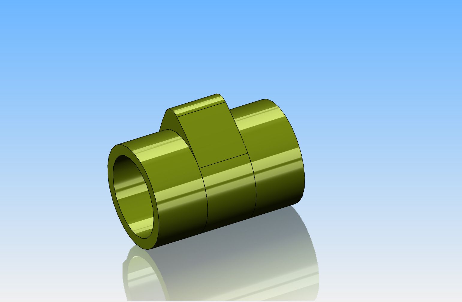
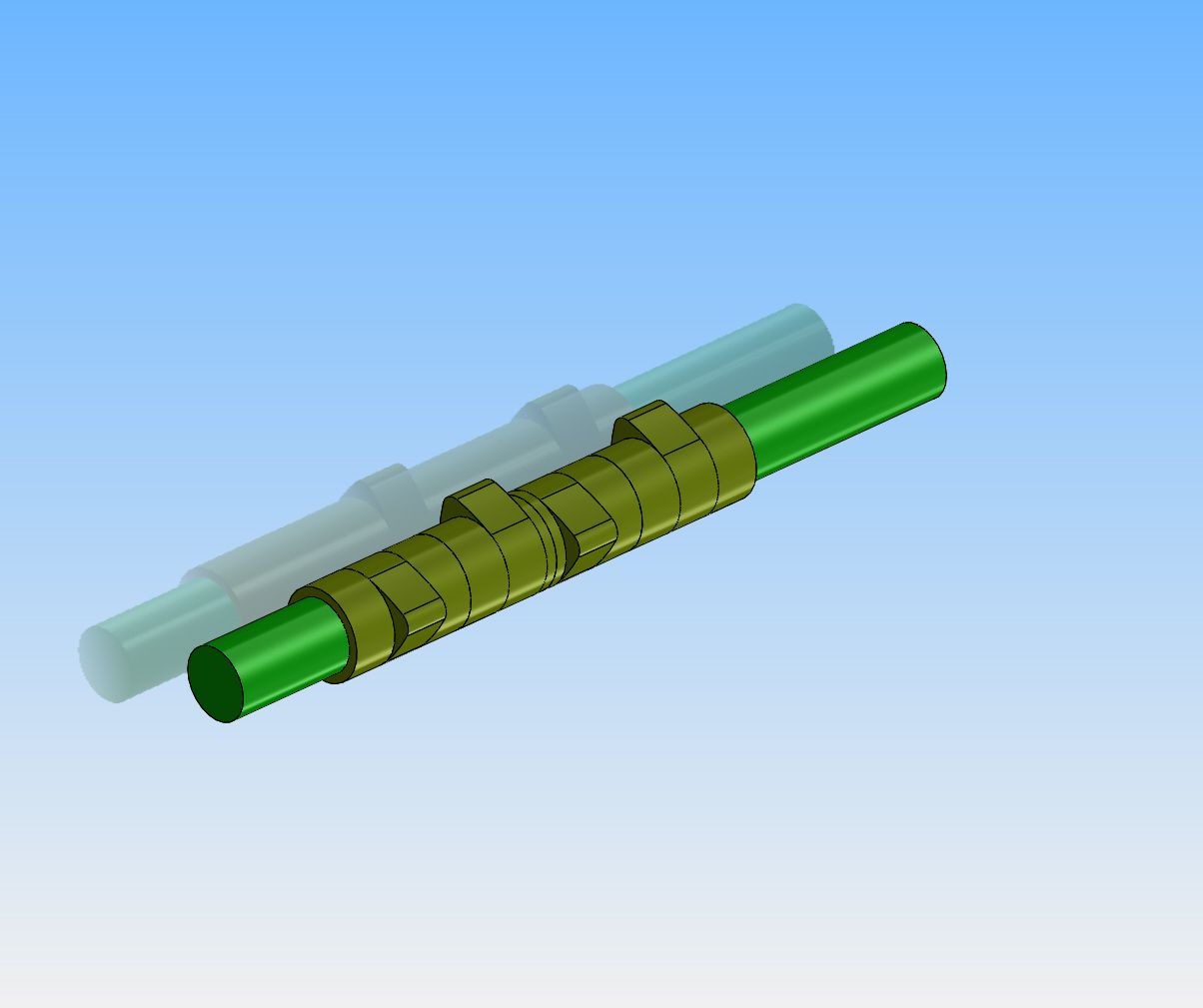
This week I hope to make my four cams, using the Cam-Calc software provided by the Model Engine News folks. This is the method which uses a rotary table and a vertical milling machine. It is not difficult-----just very time consuming. The i.d. of the cam is 1/4", the o.d. of the sleeve is 0.315", and the lift of the cam is 0.067". The total length of the four cams mounted end to end is less than 1.6", and if I make a one piece cam and allow three 0.100" spaces for my 3/32" parting off tool, it is still less than 2" total length. The cams get Loctited to a piece of plain 1/4" cold rolled steel to make up the cam shaft. The cams themselves are made from 01 steel and flame hardened. That outer sleeve diameter of .315" is equal to the "base radius" of the cam itself. I am going to try and cut one cam 2" long, with a reamed bore of 1/4" full length, then use my parting off tool to turn the round areas to 0.315", while leaving the actual cam portion unmachined. Then I will use my 3/32" parting off tool to cut the one piece cam into four individual pieces which will be hardened, then arranged rotationally and Loctited to the shaft. If this works, it will save me the work involved in cutting four individual cams.


Last edited:
As much as I would like to take credit for the original design of the cam, and explain the science and reasoning behind it, I can't. This design is originated by Malcolm Stride of the U.K. and used on his "Bobcat" twin and "Jaguar" single cylinder engines. I have put considerable time and energy into studying all of the factors which go into cam design, and I have sufficient knowledge to design a cam from scratch, using formula's developed by Stride and by Mason. However, this is one of the instances where I don't fully understand the science involved. I just know that it works, because many people built the twin cylinder "Bobcat" using this cam and posted videos of the engine running. I did build the single cylinder "Jaguar" version, again using this exact cam, and it ran, although I never was able to resolve the issue of it occasionally expelling jets of vapour thru the carburetor intake. Since I only began machining things about 6 years ago, I believe the occasional jets of what appeared to be exhaust vapour thru the carburetor intake may have been more of a testament to my questionable machining ability than anything to do with the cam design.---Brian
Todays offering to the Machining Gods are four valve cages. I purchased the compression spring in the picture this morning, as I wanted to have it before I machined the cages. I have a valve inserted into one of the cages (The valve still has the "handle" attached to it). These cages have to be Loctited into the cylinder head, and although it should be a light press fit, you really can't press them too much or they deform. I have ordered some Loctite 620 retaining compound, as it is supposedly much more heat resistant than the 638 I have always used. I will not put the valve "seat" into the valve cages until after they are Loctited into place.


Similar threads
- Replies
- 61
- Views
- 8K
- Replies
- 31
- Views
- 3K


