Opposed Twin I.C.

Home Model Engine Machinist Forum

Help Support Home Model Engine Machinist Forum:

This site may earn a commission from merchant affiliate links, including eBay, Amazon, and others.
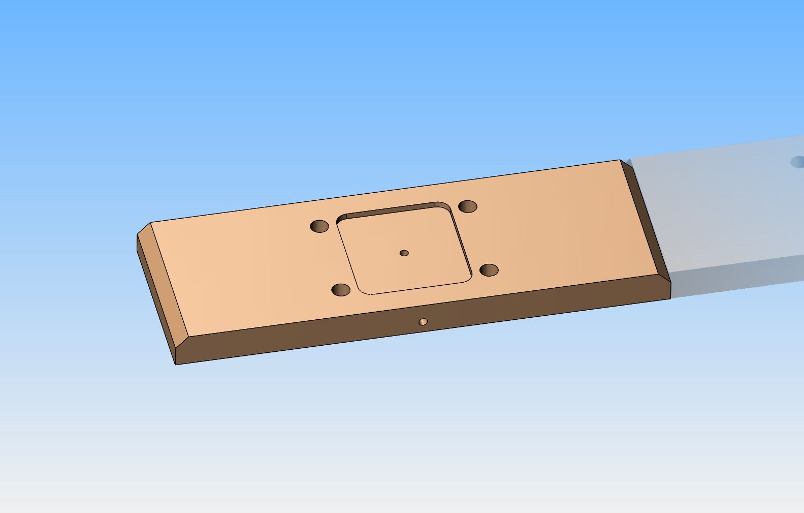
I've reached the point in this build where I need a bit more stable platform to set things on as I add them. I didn't want to invest any more time/work until I was sure that I was going to be able to make the crankshaft. Now that it is finished, I will go ahead and build the engine baseplate. This is not going to be an "oil in the base" engine. Oil will be administered from the open top, via squirt can. The milled "catch basin" in the baseplate will catch any oil drips and guide them out thru a drain hole in the front of the baseplate. I will probably put a perimeter gasket between the "engine block" and the baseplate to keep oil from seeping out onto the surface of the baseplate..
 
And---we have a base. Not much to brag on here, because all the "features" are hidden inside the engine block. Still, it used up an entire afternoon, and it fits!!!
 
Hi Brian.

You have given me the courage to machine crankshaft.
Looking for video on the first start and run.
 
Hi Gus--glad you looked in. I hope everything is working out well on your engine.---Brian

Hi Brian,

Gus at 72 does get burnt out easily. Howell V-2 has too many small parts and all require my best concentration. No worry. I am now in the final assembly stage.
To add to my woes, I cannot post fotos. Need the latest iPhoto download. My Apple NBook was just reformatted with the latest Apple d/loads. The New Apple 6S HandPhone takes time to get used to. With Christmas around the corner,I am getting lazy.
 
This kind of puts me in mind of the old Doublemint gum jingle--"Double your pleasure, Double your fun!!!" I've spent a goodly portion of the past two days making cylinder heads. Each head has 5 drilled and counterbored holes, 11 tapped holes, one 1" counterbore, and two reamed and counterbored holes. I have not yet drilled the holes through that top surface with the 8 tapped holes in it to connect it to the valve cage holes. I will wait until the valve cages are made and installed, then drill thru the cylinder head and the valve cages at the same time.

 
This kind of puts me in mind of the old Doublemint gum jingle--"Double your pleasure, Double your fun!!!"
Brian
Your DRO have the function to do that for you
take minute, OK afternoon and check the tutorial
it does a lot more than giving you numbers:wall::wall:
it give you ANSWERS ALSO Rof}Rof}Rof}
 
Today I made a cam bushing. It's a bit more than a standard issue bushing though. It has a flange which bolts into a pocket in the side of the "engine -block" and an extended nose which fits into a reamed hole in the side of the engine block to keep everything aligned. It is made from bronze, and with this design I can remove the bushing and pull the camshaft with cams attached out through the front of the engine. The end of the extended nose also acts to position the camshaft longitudinally. The shaft in the picture is just a random length of 1/4" c.r.s. right now. The cams will be made seperately and attache with Loctite. (This works, and works very well. It is the method Malcolm Stride used on hid "Bobcat" engine.) The pocket in the side of the engine block is very precise, as it was cut on the mill. The perimeter of the cam bushing was shaped by hand, so it isn't a perfect gap all around. This is okay though---it all gets covered up by the gears and gear cover.


Last edited:
We've got gears!!! They seem to mate and mesh properly, but I have to finish a couple of plain bushings, one for the crankshaft and one for the camshaft before I'm 100% certain. I only make about 3 or possibly 4 sets of gears each year, so I have written step by step instructions for myself in my "Gear book". It is simply a matter of coincidence, but these are the same gears that work on the Webster engine. The actual gear cutting is very simple if you have a rotary table and a set of gear cutters. The "work" is all in preparing the gear blanks to the correct size.
 
This falls under the heading of "creative fettling"!!! Although the gears turned out well, my center to center distance on the frame holes was out by about .015", too close together. I'm never quite sure how something like this happens, but it does. Sometimes the hole spacing is "right on", and sometimes they are a bit too far apart. "Right on" is great---nothing more required. If they are a bit too far apart, it's still okay, but the gears may be a bit noisy when the engine runs. When they are a bit too close---Well, still no cause for a major rework. I simply set the gears up in the lathe and turn .008" off the tip of the teeth. This still leaves lot's of tooth for engagement. Once the gears will turn in place (Albeit a bit stiffly and nasty) then I apply a bit of 400 grit carborundum paste to the gears, put a pulley on the crankshaft, and power it up with my 1/2 h.p. bale elevator motor. After a half hour run in, everything turns as smooth as silk.

 
I thought of building a sub base from wood to raise the engine up enough to get clearance for the flywheel shroud---but I don't really care for woodwork all that much. I have come up with a design using 2" x 1/2" aluminum bars for the risers.
 
Hi Brian
for some reason I was under the impression
that It would have two carbs
Looking good Thm:
 
Luc--I thought about two carbs. I still may go that route. It's just that with two carbs, you need a connecting link to synchronize them.---Brian
 
10k Pete---As you can see by my post count, I've been around here for a while. If you go back to the beginning of this thread, you can see how the current model "evolved" from my first ideas of designing a two cylinder opposed engine. I think this is my fifteenth or sixteenth engine build. I bought my first lathe and mill about six years ago, and manage approximately two engines a year.----Brian
 
The time has come in this build to do a bit of finishing and a bit of verifying. I hadn't touched the inside of the cylinders, other than to ream them to size when I was originally machining them. Now that the crankshaft and camshaft are turning freely with gears attached it was time to check that the center of the connecting rod journals were lined up with the center of the cylinder bores. The way I finish my cast iron cylinders after reaming them is to run my three stone brake cylinder hone thru them under electric drill power, at a fairly low rpm, and everything covered with a bit of light oil. I run it back and forth for a rough count of 40 times, being sure to not let the jaws 'spring' out of either end while doing so. Then I turn a piece of round aluminum stock to .002" smaller in diameter than the cylinder bore, coat it with 600 grit carborundum paste, and put one end of the aluminum piece in the lathe and at low rpm slide the cylinder back and forth over it for about two minutes as it rotates.---I then turned one end of the homemade lap down to 0.375" diameter, and with the cylinder heads removed I slid the lap down the cylinder bore until the 3/8" end come out into the cylinder block. --In a perfect world, if everything was machined precisely, it would have fit perfectly into the gap between the crankshaft "throws".---In my world, I had to set the crankshaft up in the lathe and machine .025" off the outside edge of one of the "throws", and that did the trick quite nicely, as you can see in the picture. I think that now I will go ahead and make the pistons and con'rods.

 
Back
Top