Nemett Jaguar--Canadian style

Home Model Engine Machinist Forum

Help Support Home Model Engine Machinist Forum:

This site may earn a commission from merchant affiliate links, including eBay, Amazon, and others.
Brian,

Thank you for your detailed description of your crankshaft-building process and for the drawings of the fixture. I was interested to see numbers for the runout and your home-shop method of dealing with it. I have become overly paranoid, I think, about getting perfect results when so many have talked about half-a-thous so much and implying that perfect (read expensive) equipment is required to do such work. I have attempted several things in the last year that I set aside as too rough and never posted.

Thanks again, your projects help keep me interested in this hobby.

--ShopShoe
 
  • Like
Reactions: gus
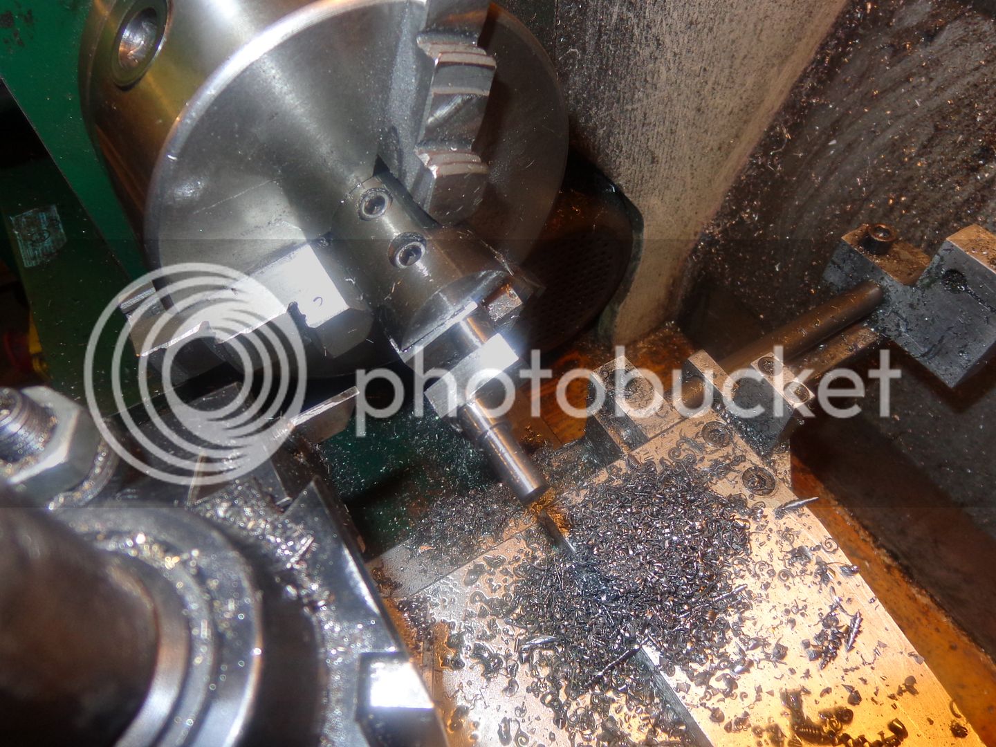
The first picture shows the crankshaft setting in the fixture before I put it in the lathe. The second shows it in the lathe. The cut-off tool in the picture was used for all of the machining of the rod journal. I ran the lathe on its lowest speed which is 115 RPM and used a set of home made carriage stops that I set up prior to starting the lathe to ensure that I wouldn't feed the tool too far to either side and machine away material on either side of the journal. (This would have been immediate disaster and a ruined crankshaft.) i used the carriage lock-down bolt to lock the carriage in position while cutting. I very slowly plunge cut with the tool tight against one side side (tool is .093" wide), until I was no longer taking an interrupted cut. Then backed out the tool, unlocked the carriage and moved over .080" and cut to the same depth as previously cut. I kept doing this until I was tight against the other carriage stop. Measuring the resulting diameter showed me that I still had about .040" of material to remove, so I speeded the lathe up to 210 RPM and taking .002" depth of cut I traversed the carriage back and forth manually from carriage stop to carriage stop, cranking it in .002" for each pass. I stopped when the diameter reached 0.396" and then backed the tool completely out of the way and set the lathe speed at 550 RPM and used a 3/8" wide strip of #220 grit emery cloth to work the journal down to 0.394" (10mm).

 
One last crankshaft related topic, and then I promise to shut up about it. Everybody has questions about and issues with the run-out of crankshafts machined from solid. Firstly, I will say that the stress proof 1144 steel is a very nice steel to machine. Next, about the runout--I knew there would be some run-out. I don't use collets, and my 3 jaw chuck has about .003 total indicated runout. (That means it is .0015 out of "true center"). Before I did the final machining of the rod journal, the runout had grown to about .013 TIR as measured by holding one end of the crankshaft in my 3 jaw chuck and indicating the far end of the crankshaft. After machining the rod journal, the reading had dropped back to about .006" TIR. (I won't explain the "why" of this---I'm just reporting the figures I seen.) A couple of light taps on the end of the crankshaft farthest from the chuck with my dead blow hammer, and the reading dropped back to .002 TIR which I considered was as good as I was likely to get.
 
Last edited:
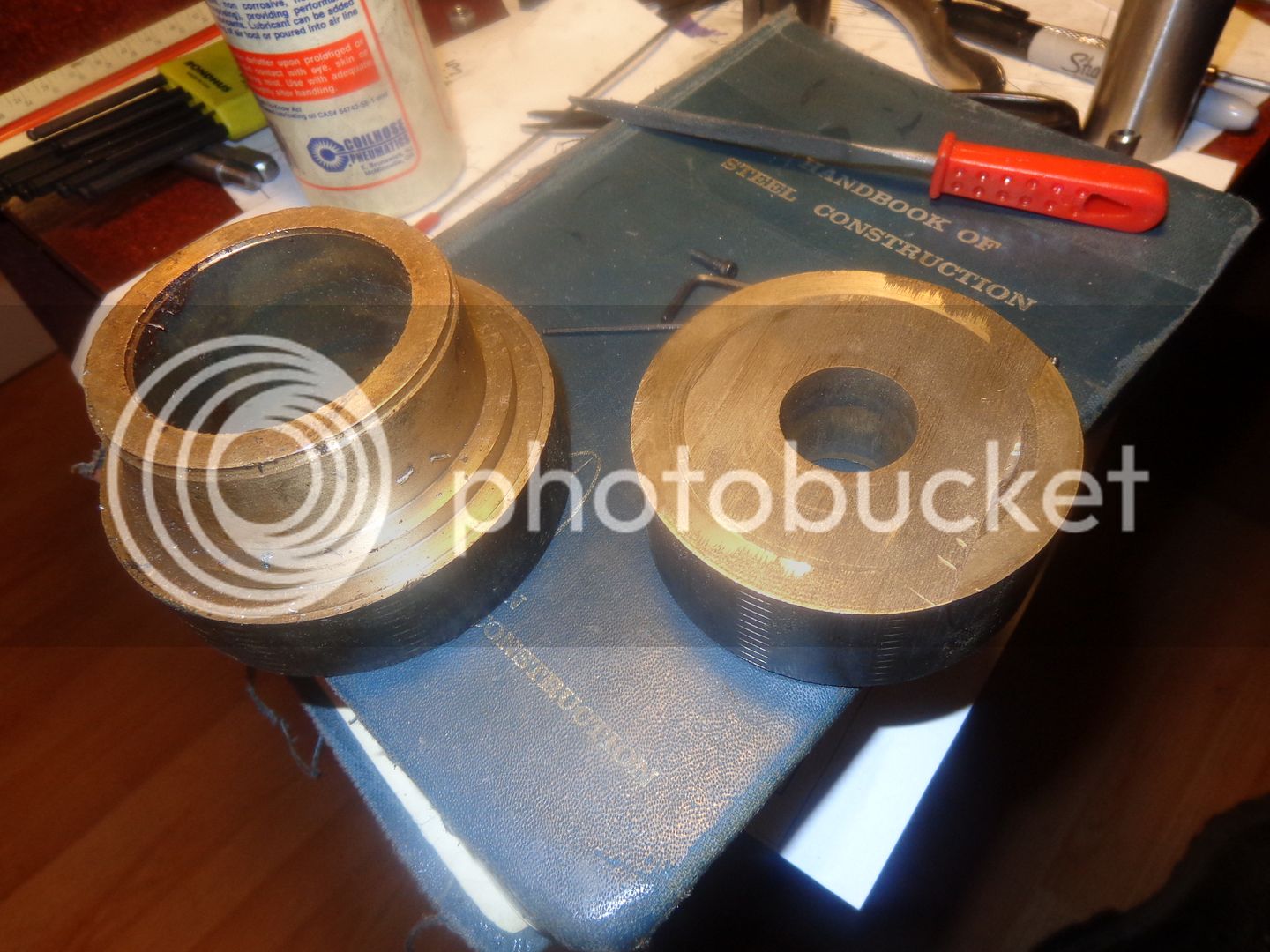
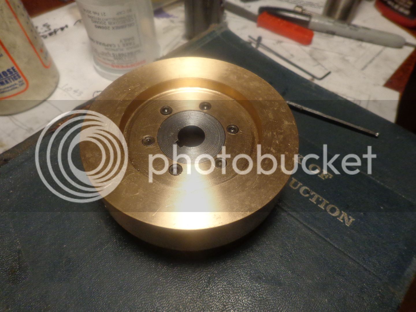
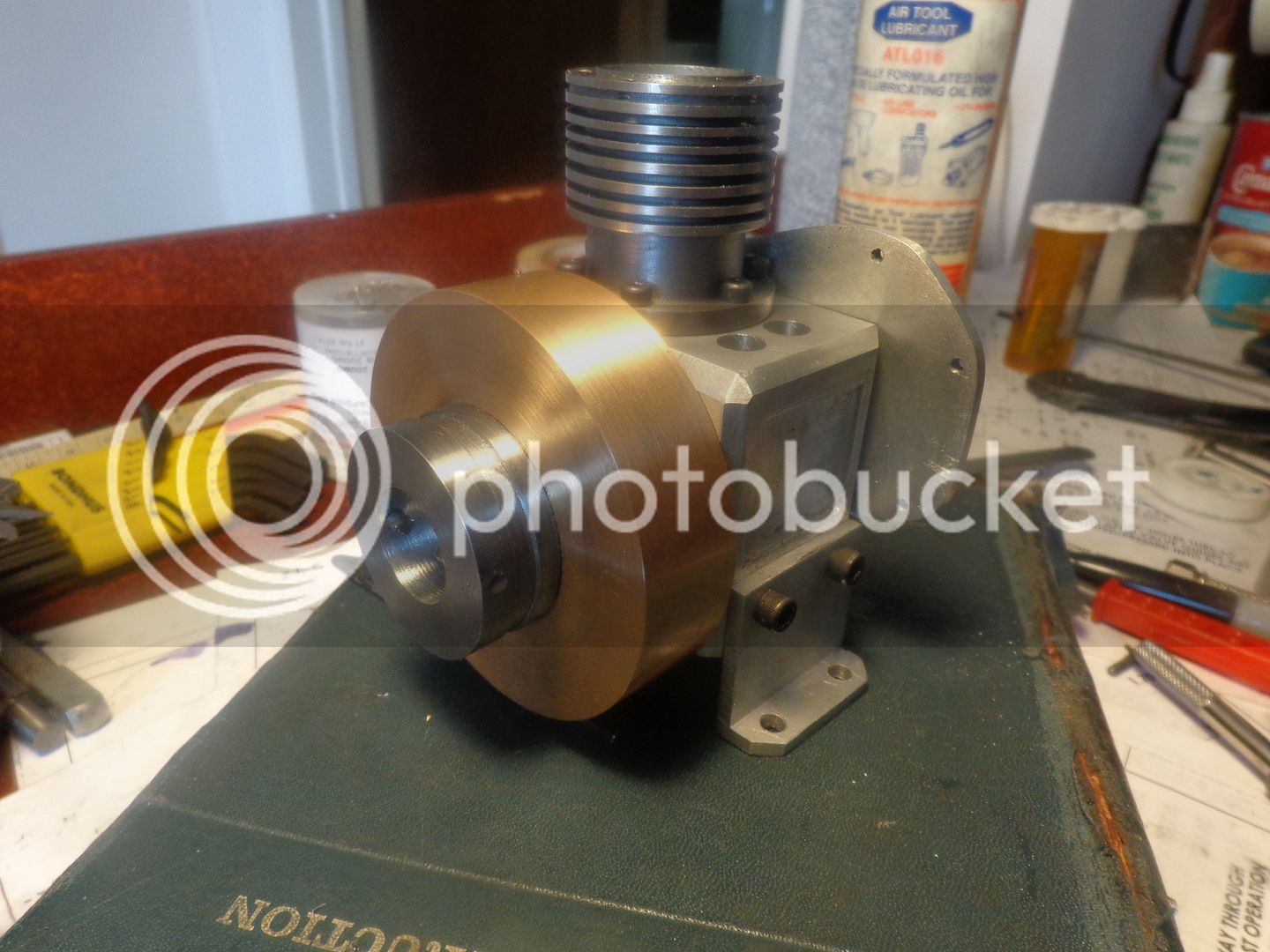
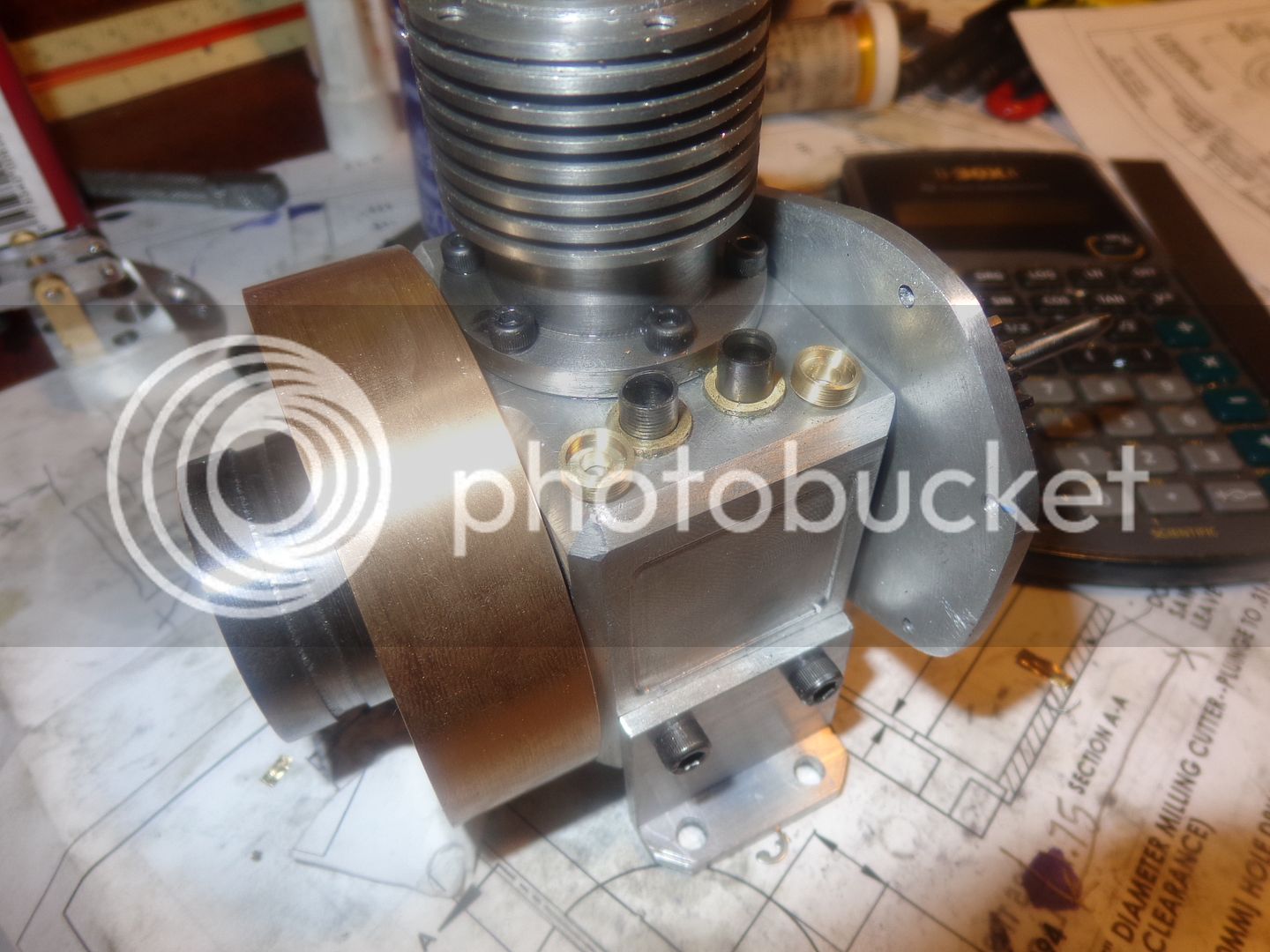
A week ago when I was at my metal suppliers, I picked a couple of pieces of 3" diameter bronze out of the scrap bin and paid something like $20 for them. Today I decided to build a two piece flywheel with a steel center, and I used the piece of bronze with the smallest hole in the center. There is absolutely nothing I can post about flywheels that hasn't been posted about a hundred times before. I have included a picture of the "back" side of the flywheel, showing how the bronze outer ring is centered and attached to the steel center part, and a picture of the flywheel on the engine. You can also see in the shot of the flywheel on the engine how I have incorporated a pulley and my "starter dogs" into the flywheel.


I had purchased a piece of 3/4" thick bronze to make the gear cover out of, but I hate machining bronze. It's kind of like "Death by hot powder bombardment!!!" I have an old full face welders helmet that I took the colored lens out of and only have the clear lens in, and I use it for machining bronze. I can see where this is going to be a beast of a thing to machine manually, so as of now my plan is to make it from a piece of brass reclaimed from that 50 pound brass weight that found its way to my place.
 
I had purchased a piece of 3/4" thick bronze to make the gear cover out of, but I hate machining bronze. It's kind of like "Death by hot powder bombardment!!!" I have an old full face welders helmet that I took the colored lens out of and only have the clear lens in, and I use it for machining bronze. I can see where this is going to be a beast of a thing to machine manually, so as of now my plan is to make it from a piece of brass reclaimed from that 50 pound brass weight that found its way to my place.


Hi Brian,

You are not alone. I dread turn/milling brass and bronze. It gets all over me.
Watch the tinny bitty needle-like swarfs. Cast Iron gets all black and rusty.
The bathroom tiles too. Had flush and scrub after every shower. My darling boss gets mad at me for messing up her immaculate bathroom.
 
Your descriptive texts are inspiring Brian. Any article by you or George B. gets my immediate attention.
 
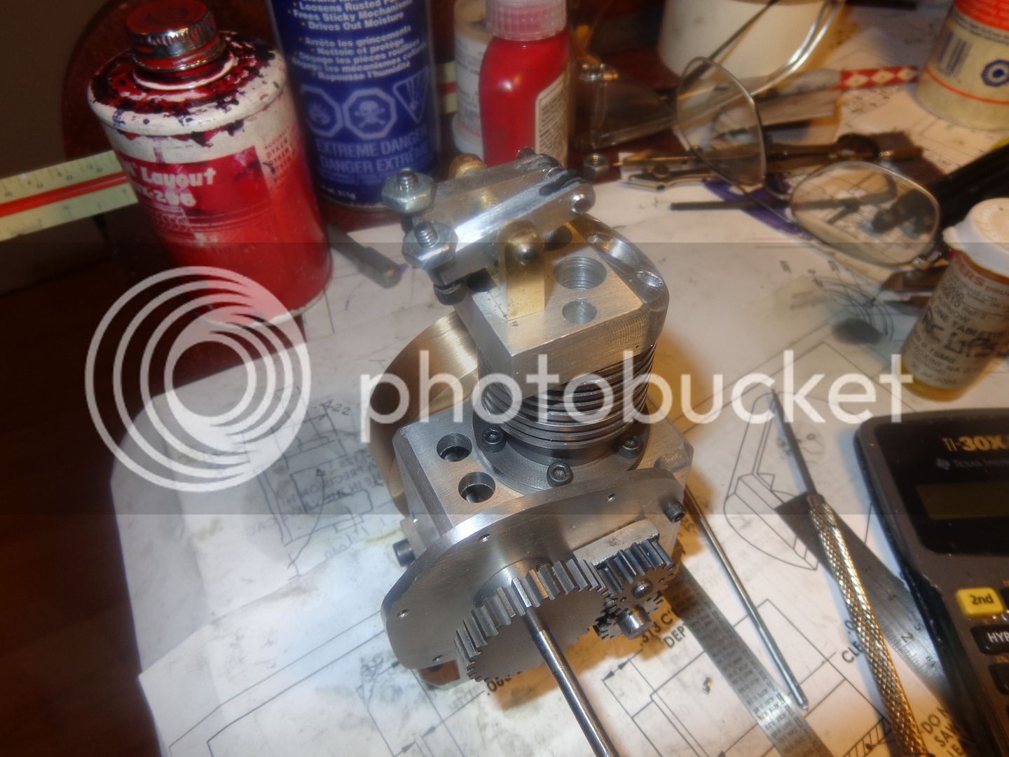
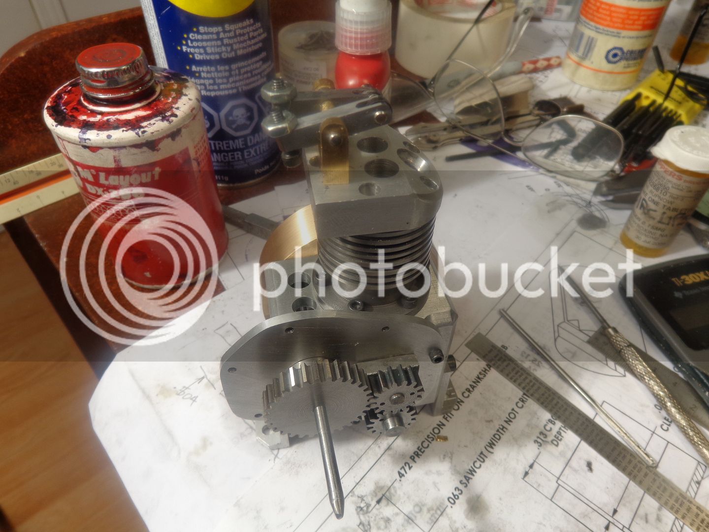
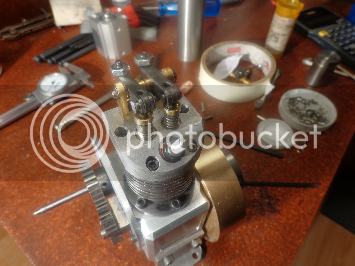
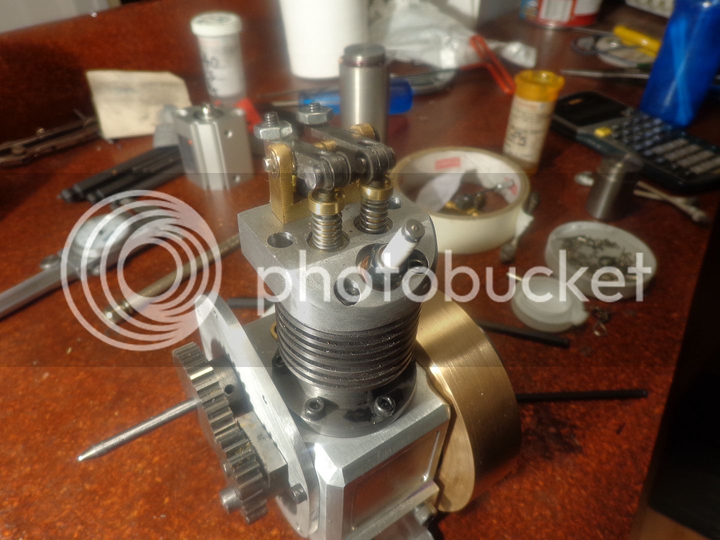
I spent the lions share of today making the smallest parts on the engine. I'm still not finished---For some reason none of my grooving tools want to cut today, so the 1/8" shafts holding the rocker arms and their bearings in place are just "dummied up" for the picture. I tried 3 different times to capture a good picture of what I had done, but this is as good as I was able to get.

 
Hi Brian,

With every engine building and the major parts done and there seems to be no end to big pile of small parts. I have given up counting.The simple looking overhead cam box took six hours to do.:rant:
 
Six more itsy bitsy pieces this morning, Valve lifter guides, valve lifters, and spring keepers for valves. Why does the one lifter have annular marks on it?--why for oil retention, of course!!! Why doesn't the other lifter have annular marks on it?---Err---Ummm----Damn, I was hoping nobody would ask me about that---
 
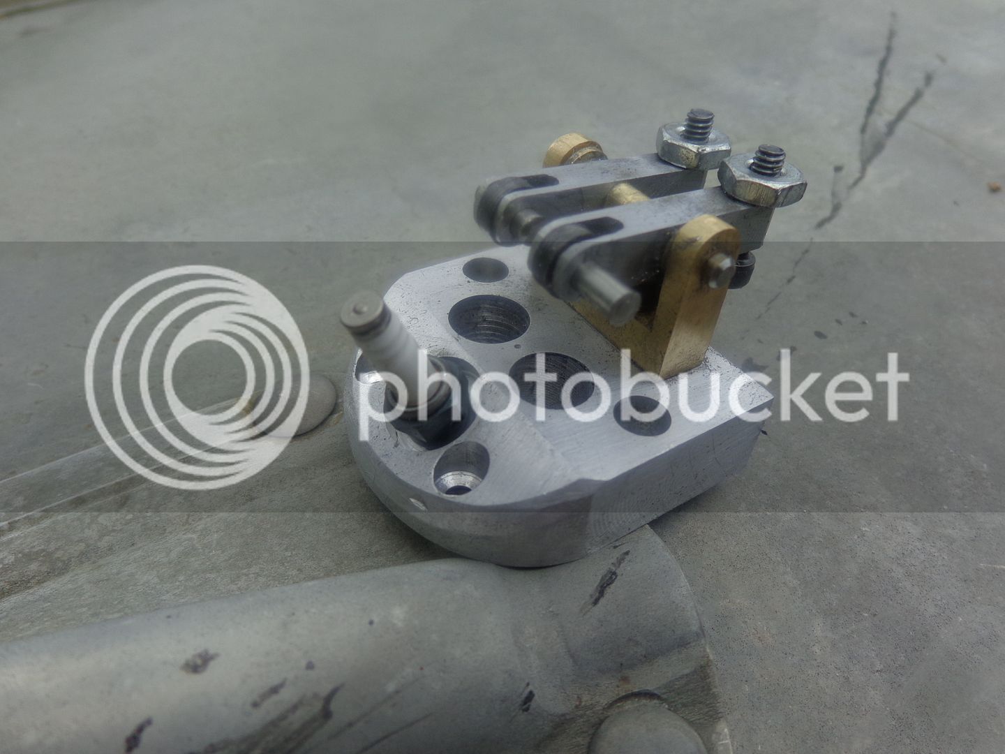
I just picked up my mail today, and Roy Sholl of S&S Engineering has sent me the smallest spark plug I have ever seen in my life. It is a Rimfire VR2 with 1/4"-32 thread. I had already purchased the tap, but didn't want to use it until I had the plug "in hand". All appears to have went well. The plug comes thru into the combustion chamber at an angle of 28 degrees, and the threaded portion at the end of the plug just comes flush with the interior face of the head. This leaves the electrode a very tiny bit "recessed" but I don't think it will hurt the performance.
 
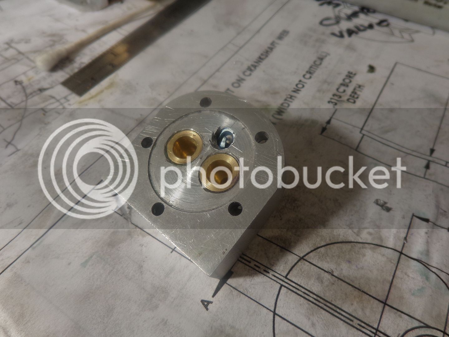
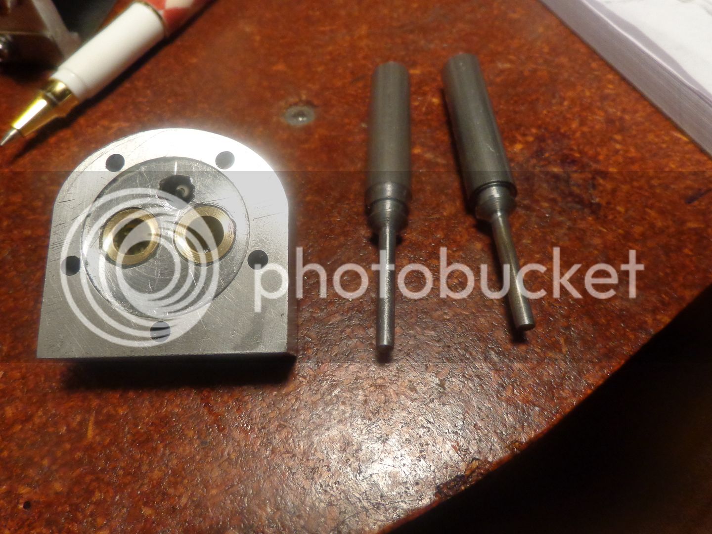
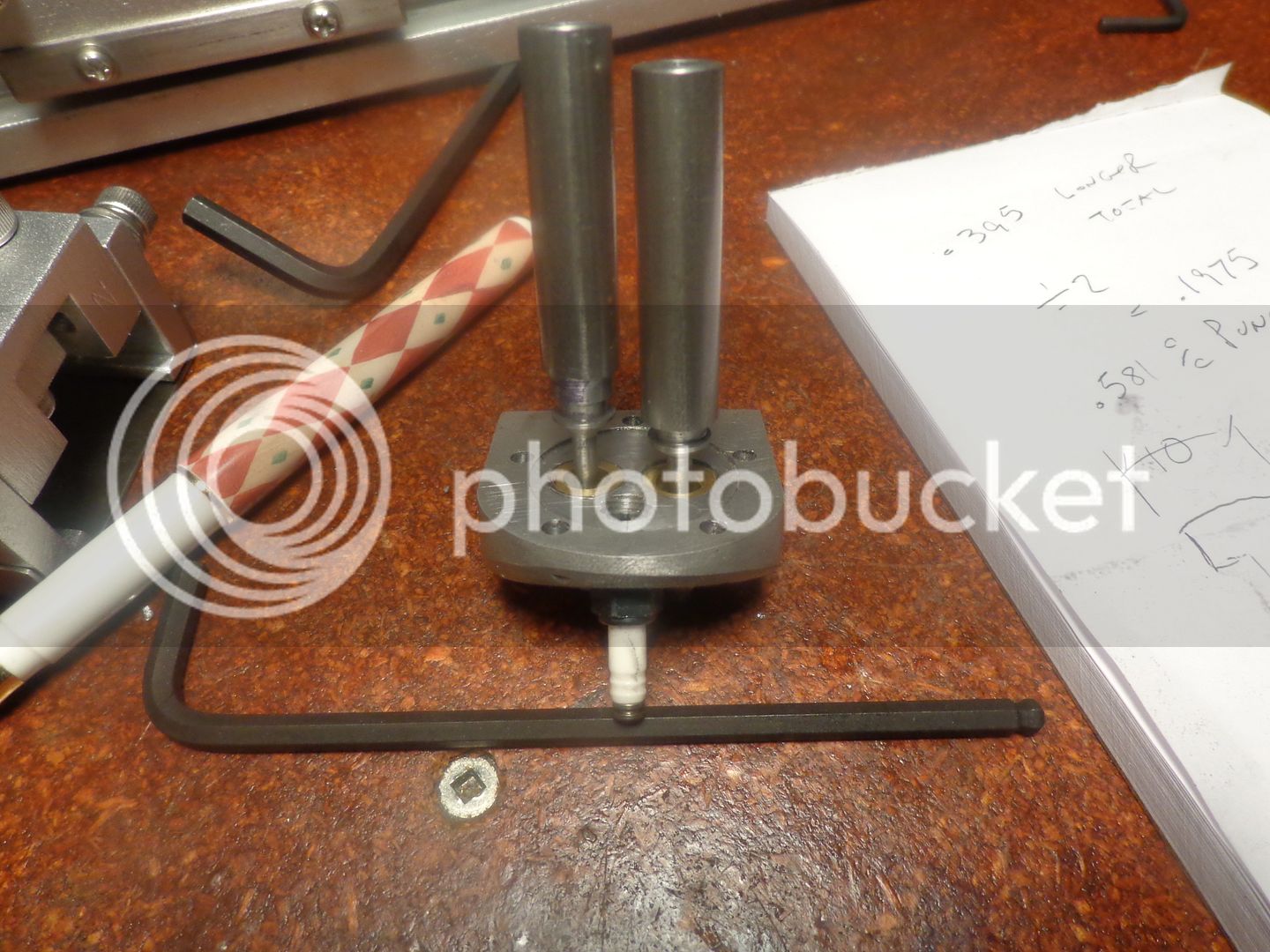
This afternoon I machined the valve cages,pressed and Loctited them into place, and using my special George Britnell tool I put a .010 to .015" x 45 degree chamfer on the area where the valve will seat. I wasn't going to post this shot, because I know the camera will pick up every bit of nastiness that is there and make it look worse than it actually is. Then I decided "Hey--This is reality!!!" The inside of that cylinder head will never be seen again once the engine is assembled, and it doesn't have to look perfect, as long as it functions perfectly and the valves seal all right. So---Here it is, warts and all!!---Brian
 
Yup, We're both working on the same end of the engine. I got valve assembly pretty well wrapped up today. Just need to tidy it up some.

Chuck
 
  • Like
Reactions: gus
Nothing accomplished today!! Got a call last night from a customer who has a few days engineering work so I'm busy at that for a couple of days. I needed a break from the engine anyways.---Brian
 
  • Like
Reactions: gus
This morning, while waiting for a customer call back, I went ahead and made my valves from cold rolled steel. Although the valves themselves are essentially finished except for a cross hole at the end of the stem for the spring retainer, I have left the parent stock from which they were turned attached. This gives me a very convenient "handle" for rotating the valves back and forth with my fingers as I lap them into the seats. I will use a succession of 350, then 400, then 600 grit to do this. I will then drill the cross holes and cut the valves away from the parent stock. At this point I like to match mark the valves to the guides they were lapped into so I don't mix them up. ----I'm not sure that's a big deal, but ANYTHING involving valves is a big deal. I would rather spend the extra time and caution at this stage than after the engine is finished and won't run because of leaky valves.

 
Hi Brian,

I like your method of holding the valves for lapping. Are you using SuperGlue or Loctite. Will be turning/lapping the tappet valves next week.
 
Gus--You are looking at the parent stock that the valves are made from. I haven't parted them off yet. Read what it says in the text with the pictures.---Brian
 
Gus--You are looking at the parent stock that the valves are made from. I haven't parted them off yet. Read what it says in the text with the pictures.---Brian

Hi Brian,

That was a very smart move. So many ways to skin a cat.th_wav

Learned something new today. Home Gus did not think of using this method to lap valves for Webbie and your Rupnow Engine.
 
My mother used to say that small, picky, tedious jobs were like "picking fly$hit out of pepper." This job I have just finished is about as close to that description as I ever hope to get. The valves are finished, trimmed to length, lapped into the seats, and have the springs and keepers installed. The rocker arms are set up with their own shafts, (Let me tell you some time how much I hate e-clips!!!) I think the next move I make will be to machine the cams. Malcolm Stride gives a method where by using a rotary table in conjunction with a vernier downfeed in a milling machine, cam profiles can be generated. The rotary table turns the cam in one degree increments and the milling cutter is lowered a specified amount each time based on information given in a chart until a cam profile is generated. I have never done this before, but it sounds logical, so i will give it a whirl.


Latest posts

Back
Top