
You are using an out of date browser. It may not display this or other websites correctly.
You should upgrade or use an alternative browser.
You should upgrade or use an alternative browser.
My 4" scale steamroller project
- Thread starter Allen
- Start date


Help Support Home Model Engine Machinist Forum:
This site may earn a commission from merchant affiliate
links, including eBay, Amazon, and others.
Allen
Well-Known Member
- Joined
- Jul 14, 2008
- Messages
- 128
- Reaction score
- 55
Don't it figure, I made some good progress today despite the heat, but forgot the camera.....
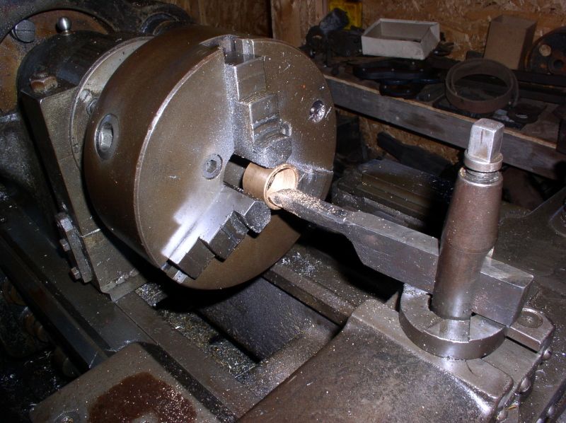
The big project was a new crankshaft. I got to use the big lathe in the 1892 Hoffman Machine Shop at the Portersville Steam Showgrounds to do it, too! (see the sprocket boring pic above!) --- The Mason engine has a 3/4" shaft. The McCormick thresher pulley I'm using for a flywheel, and dog clutch a friend gave me are 1-1/4". I thought about making a sleeve, but it would have needed to be about 7" long, and I was worried about the possibility of bending the crank if somebody hung a belt on it, anyway. Sooooooooo, since I had a 2 foot piece of 1-1/4" shafting "seasoning" in the shed, I decided to polish it up, then turn it down on one end to 3/4" for about 8" and be done with it. It looks kind of funny (the governor pulley is at the transition, so the shaft is skinny on one side and fat on the other), but it's totally functional. I'll probably use two pillow blocks on the flywheel end since I have them to keep as much stress off the small part as i can (overkill? nah....hehehehe)
The other project was boring out a #40 sprocket to fit the nice riding mower differential I have (Jacobson? it's orange anyway)... it's only 40 tooth, but the one that was on it was 32 tooth, so it's at least a bit larger. I did the math, @ 250 rpm it should go about 3MPH... A little faster than I'd prefer, but I don't have a 50 tooth sprocket.
There was no fan in the shop. I probably lost 10 pounds in sweat, so I quit after I got those done. Maybe I need to lose a little "insulation"?
Allen
Well-Known Member
- Joined
- Jul 14, 2008
- Messages
- 128
- Reaction score
- 55
It was just too miserable hot by 9AM to even consider going over to work today. So I assembled the differential sitting on the livingroom floor. I was careful not to make a mess but Kim still wasn't amused. What is it with women and that old bearing grease smell? Men don't (usually) complain about their stinky flowers..... ???
At least I'm still allowed to sleep indoors, and I even got a couple pics to share!
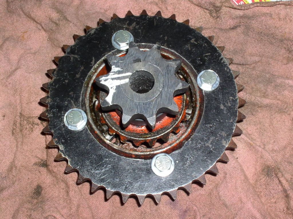
This is the twin brother of the #40-40T plate sprocket I cut yesterday as a "before" pic:

And how my amateurish machining job turned out:
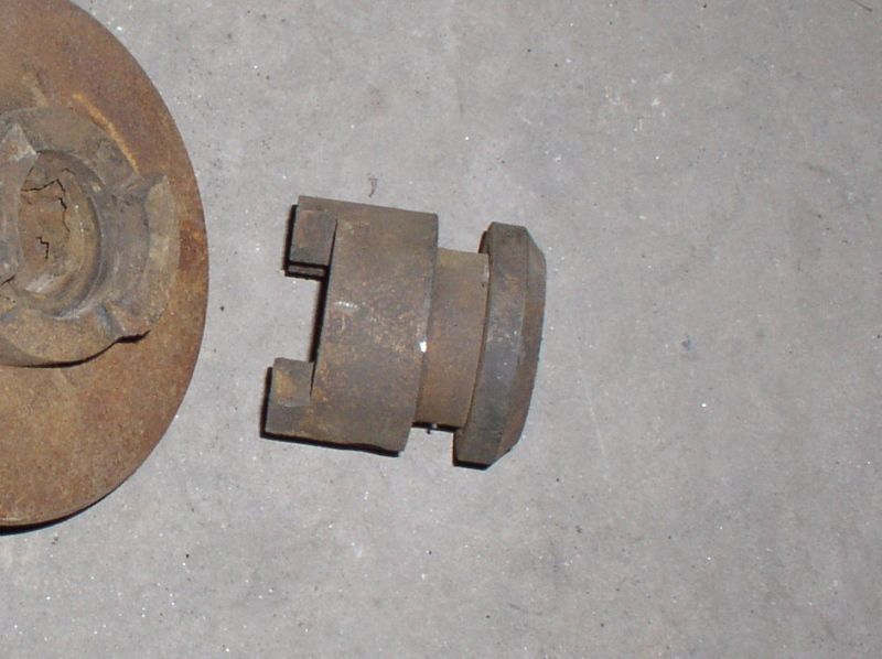
This is business part of the pinion clutch I was given. I "milled" mating dogs on the inside end of the flywheel hub with an angle grinder, then dressed everything up with a file to reduce the stress risers. The hub casting is about 7/16" thick, and the roller is only intended to pull itself, so I'm hoping to get away with it. If it breaks I still have the mating part from the clutch in the shed. I'll be turning down the taper part to mount a 15 or 16 tooth ring sprocket. which will give me a about 2.5:1 reduction to the differential countershaft. I'd prefer at least 3:1, but simply can't afford the asking price for a new 50 tooth sprocket!
More pix coming when I get them....
At least I'm still allowed to sleep indoors, and I even got a couple pics to share!
This is the twin brother of the #40-40T plate sprocket I cut yesterday as a "before" pic:
And how my amateurish machining job turned out:
This is business part of the pinion clutch I was given. I "milled" mating dogs on the inside end of the flywheel hub with an angle grinder, then dressed everything up with a file to reduce the stress risers. The hub casting is about 7/16" thick, and the roller is only intended to pull itself, so I'm hoping to get away with it. If it breaks I still have the mating part from the clutch in the shed. I'll be turning down the taper part to mount a 15 or 16 tooth ring sprocket. which will give me a about 2.5:1 reduction to the differential countershaft. I'd prefer at least 3:1, but simply can't afford the asking price for a new 50 tooth sprocket!
More pix coming when I get them....
Allen
Well-Known Member
- Joined
- Jul 14, 2008
- Messages
- 128
- Reaction score
- 55
Some new progress (Hope I ain't boring you!), even with the miserable heat of late
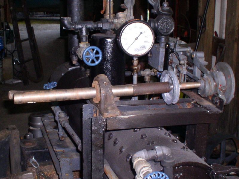
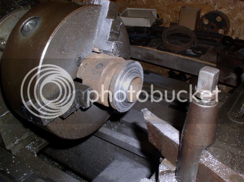
This is what the new crankshaft looks like. I need to ream the bearing bushing to fit better - as my "interference fit" completely interferes with it even thinking about going together at all.
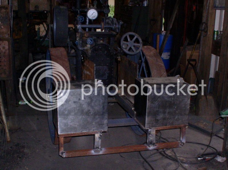
I almost talked myself out of these stainless hotdog cart coolers 3 times. Mostly because the guy wanted $50 firm for the pair.... Kim finally had enough of my dithering and bought them for me. She says they look perfect. I tend to think she might have a point, even if they do only hold about 4 gallons each.
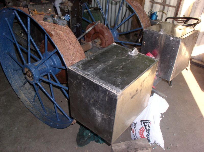
We also got a real good deal on 20 feet of 6" wide canvas belting to put on the rear wheels until finances allow us to get 1/4" x 7" flat bar rolled.
This is what the new crankshaft looks like. I need to ream the bearing bushing to fit better - as my "interference fit" completely interferes with it even thinking about going together at all.
I almost talked myself out of these stainless hotdog cart coolers 3 times. Mostly because the guy wanted $50 firm for the pair.... Kim finally had enough of my dithering and bought them for me. She says they look perfect. I tend to think she might have a point, even if they do only hold about 4 gallons each.
We also got a real good deal on 20 feet of 6" wide canvas belting to put on the rear wheels until finances allow us to get 1/4" x 7" flat bar rolled.
Allen
Well-Known Member
- Joined
- Jul 14, 2008
- Messages
- 128
- Reaction score
- 55
Sooner or later I might get the hang of using the smaller lathe. For now it's about all I can do to get the bloody belts to stay on! (I think they need tightened, but it isn't my call)
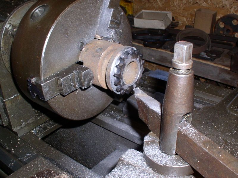
I needed to enlarge the bore on the crankshaft bushing. I'm sure I probably did it all "wrong", but this accomplished the job with very little trouble
The next project on the agenda was to turn the dog clutch to accept a ring sprocket. I got lucky there were no hard spots in the old iron casting. The sprocket is a 17 tooth #40 - the smallest that would fit without needing reboring.
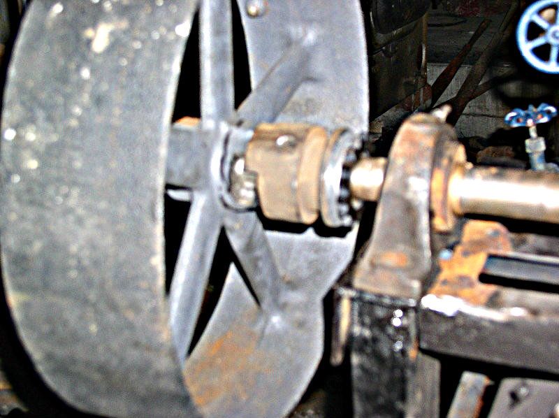
A quick mock up to double check everything shows I must not be quite as dumb as I look... It's actually gonna work!
I needed to enlarge the bore on the crankshaft bushing. I'm sure I probably did it all "wrong", but this accomplished the job with very little trouble
The next project on the agenda was to turn the dog clutch to accept a ring sprocket. I got lucky there were no hard spots in the old iron casting. The sprocket is a 17 tooth #40 - the smallest that would fit without needing reboring.
A quick mock up to double check everything shows I must not be quite as dumb as I look... It's actually gonna work!
Allen
Well-Known Member
- Joined
- Jul 14, 2008
- Messages
- 128
- Reaction score
- 55
One of the really nice things about "freescale" model building is you can change your mind, tear things out, even start over in a different direction, and it's still "right"....
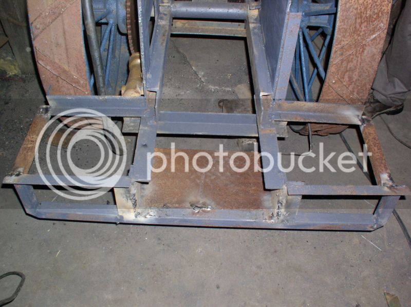
When I built the frame two years ago, I knew I was running the beads on the rear crossmember a little cold - unfortunately, with an AC box that also meant minimal penetration. So when a short weld broke (in it's and my defense I WAS doing some "precision adjustments" with an 8# hammer), I took it as permission to rethink the entire platform/bunker area.
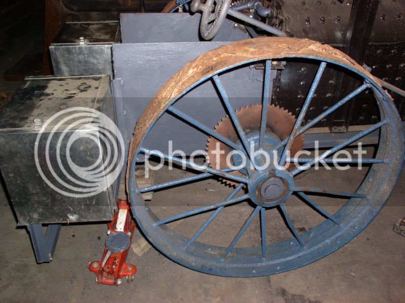
When I first envisioned this thing it was to be a true 1/3 scale traction engine. That meant rear wheels in the 25-28" range. The wheels I ended up using are 36" - making this pretty much a small boilered half scale.
It also meant the platform was well above knee level. With not much room for 1:1 scale feet, either.
The re-design will be a two level platform. The rear part will be about 5" lower than the front. Possibly allowing a lower canopy..... and more importantly it will also be nearly 3" wider. (or enough to sit sideways or turn around without twisting an ankle for most folks!)
I started cutting stuff out on Sunday, and re-welded enough yesterday to ensure I'll remember what I had in mind..... Unfortunately, with Portersville's 50th show coming up in just 2 weeks, I doubt I'll have much in the way of time in the near future to finish anything up on it!
I also had a large "durrrrrrr!" moment concerning the smokebox. I had been trying to decide for days whether it would be better to use a hole saw and hand drill or acetylene torch to cut the 3/4" hole in the side for the exhaust line. It suddenly dawned on me last night that it's just BOLTED to the boiler.... as in "simply UNbolt the thing and stick in the big drill press"....
On the plus side, even unfinished, the little roller WILL be on public display in the steam building August 2-5 for those who want a closer look. Those who've looked at it already have proclaimed it "cute as a button"... Just how cute ARE buttons supposed to be?
When I built the frame two years ago, I knew I was running the beads on the rear crossmember a little cold - unfortunately, with an AC box that also meant minimal penetration. So when a short weld broke (in it's and my defense I WAS doing some "precision adjustments" with an 8# hammer), I took it as permission to rethink the entire platform/bunker area.
When I first envisioned this thing it was to be a true 1/3 scale traction engine. That meant rear wheels in the 25-28" range. The wheels I ended up using are 36" - making this pretty much a small boilered half scale.
It also meant the platform was well above knee level. With not much room for 1:1 scale feet, either.
The re-design will be a two level platform. The rear part will be about 5" lower than the front. Possibly allowing a lower canopy..... and more importantly it will also be nearly 3" wider. (or enough to sit sideways or turn around without twisting an ankle for most folks!)
I started cutting stuff out on Sunday, and re-welded enough yesterday to ensure I'll remember what I had in mind..... Unfortunately, with Portersville's 50th show coming up in just 2 weeks, I doubt I'll have much in the way of time in the near future to finish anything up on it!
I also had a large "durrrrrrr!" moment concerning the smokebox. I had been trying to decide for days whether it would be better to use a hole saw and hand drill or acetylene torch to cut the 3/4" hole in the side for the exhaust line. It suddenly dawned on me last night that it's just BOLTED to the boiler.... as in "simply UNbolt the thing and stick in the big drill press"....
On the plus side, even unfinished, the little roller WILL be on public display in the steam building August 2-5 for those who want a closer look. Those who've looked at it already have proclaimed it "cute as a button"... Just how cute ARE buttons supposed to be?
Last edited:
Allen
Well-Known Member
- Joined
- Jul 14, 2008
- Messages
- 128
- Reaction score
- 55
I was supposed to be helping the electrician over at the showgrounds today... He was late, and it was raining anyway, so I had some time to kill.
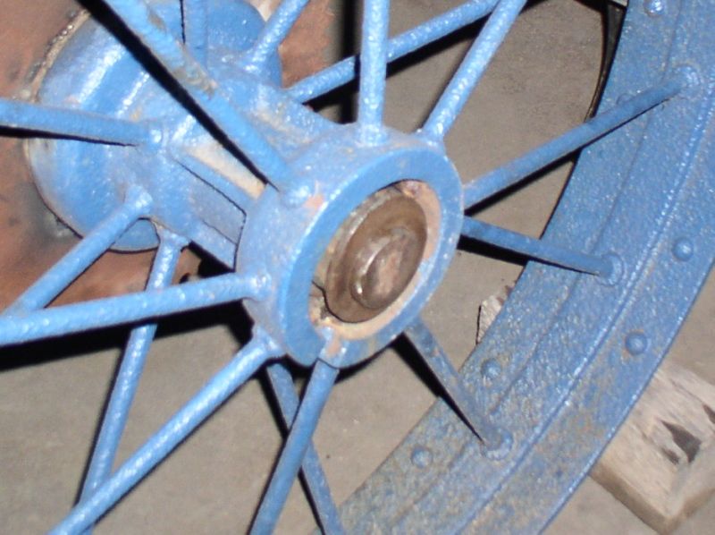
I found that the spacer collars from the manure spreader axle fit inside the wheel centers. They'll hold the wheels on just fine and also give it a nice, finished look.
I'm not a fan of welding during a thunderstorm, so I did other things. This is 5/4"x 6" deck stuff. I haven't decided whether to clear coat it or paint it grey.
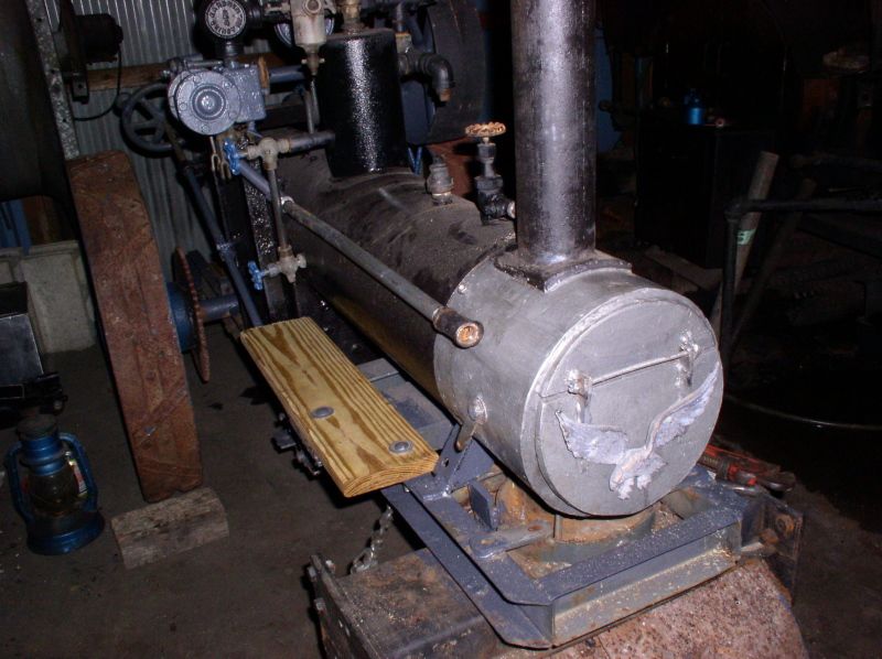
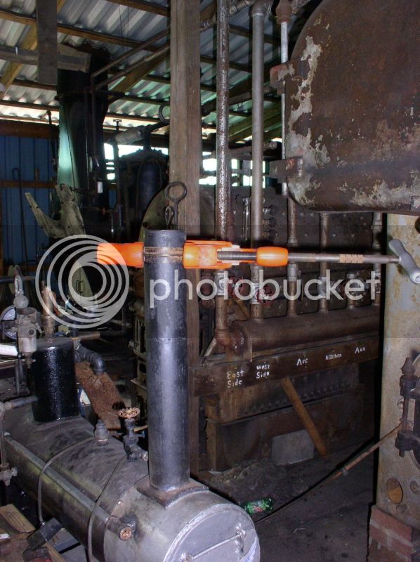
Drilling the 7/8" hole for the exhaust line took a while... but then the smokebox is the same schedule 40 as the boiler (almost 3/8" thick)
The piece needed for the exhaust pipe is an odd length. No choice but to custom cut and thread it. Luckily the club has a nice Ridgid vice and threader.
All that for this. The electrician finally showed about 3 hours late, so I didn't get the elbow and nozzle inside the smokebox installed. But I got the nipple that runs through the side screwed on, so at least it shouldn't snap the pipe off if someone leans on it.
I found that the spacer collars from the manure spreader axle fit inside the wheel centers. They'll hold the wheels on just fine and also give it a nice, finished look.
I'm not a fan of welding during a thunderstorm, so I did other things. This is 5/4"x 6" deck stuff. I haven't decided whether to clear coat it or paint it grey.
Drilling the 7/8" hole for the exhaust line took a while... but then the smokebox is the same schedule 40 as the boiler (almost 3/8" thick)
The piece needed for the exhaust pipe is an odd length. No choice but to custom cut and thread it. Luckily the club has a nice Ridgid vice and threader.
All that for this. The electrician finally showed about 3 hours late, so I didn't get the elbow and nozzle inside the smokebox installed. But I got the nipple that runs through the side screwed on, so at least it shouldn't snap the pipe off if someone leans on it.
velocette
Well-Known Member
- Joined
- Sep 11, 2011
- Messages
- 184
- Reaction score
- 54
Hi very Naughty using Galvanised pipe on steam lines will have some strange and wonderful geysers when the electrolitic corrosion gets underway
However I think it is an inspiration to us all to get out and build something that is achallenge to us. keep us posted love your work
Eric
However I think it is an inspiration to us all to get out and build something that is achallenge to us. keep us posted love your work
Eric
Allen
Well-Known Member
- Joined
- Jul 14, 2008
- Messages
- 128
- Reaction score
- 55
I really don't know where you think you are seeing galvanized. There is some old brass that's gone green and grey painted black iron pipe on this. That's ALL. (If it's the piece I cut yesterday, it is in fact "new" black iron that was painted at the same time as the frame. It was put on, then removed again when I had to re-route the feedwater lines to clear the engine mount. If you go back to the first photos of the boiler in this thread, it's on it then.)
While I thank you for your concern for my safety, I would also like to say that I'm NOT stupid. And yes, I DO get kind of touchy when folks who look at that it's built from various bits rather than a kit or commercial plans and ASSume I am. I had a boiler inspector kick once on the big 20th Century over "galvanized"... until I made him climb up and scrape the vintage brass (red bronze with a light verdigris from being on there for a decade or so) fitting with his pocket knife.
Feel free to come and inspect it. If you can find galvanized piping on this, I'll EAT it. literally.
AND just so everyone is on the same page. The boiler was designed and built to meet (actually exceed, I HAVE the relevant 1993 code books with the 1994 supplements) code, in an ASME training facility under the supervision of TWO certified code weld instructors, I did all the calculations, had my ASME welding certs, and EVERY joint setup was destructively tested multiple times before construction began.
In short, please, please, please never ASSume, always ask instead.
Allen, I'm impressed. That is quite a gathering of parts and it looks like a wonderful creation. Can't wait to see it put together.
Did you design the boiler yourself?
As far as I know in Utah where I live, there are no special boiler codes for models and it is not legal to just build your own without the proper credentials and state boiler inspections etc.
I am a welder and machinist by trade and have built a small vertical boiler but can't take it out in public.
The locomobile engine I building will have to run on compressed air or be steamed in secret on my own property....
I wish they would do some standards for just models here, but I'm afraid there is not enough interest.
Is the engine literally a Manson cut in half?
Mike
Allen
Well-Known Member
- Joined
- Jul 14, 2008
- Messages
- 128
- Reaction score
- 55
Yes, Mike. Literally. It looks like they simply ran the cylinder through a bandsaw then brazed a plate across the opening. Best I can guess is the other half went for a model traction engine.
I also had a second half Mason (both the same side) that someone else had done similar, but even less skilled things to. Then ANOTHER guy started to fabricate the missing cylinder from pipe and bar. I bought it to get the Stephenson's valve gear parts. Oddly enough, I resold that one for more than I paid.
I also had a second half Mason (both the same side) that someone else had done similar, but even less skilled things to. Then ANOTHER guy started to fabricate the missing cylinder from pipe and bar. I bought it to get the Stephenson's valve gear parts. Oddly enough, I resold that one for more than I paid.
Allen
Well-Known Member
- Joined
- Jul 14, 2008
- Messages
- 128
- Reaction score
- 55
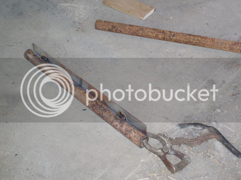
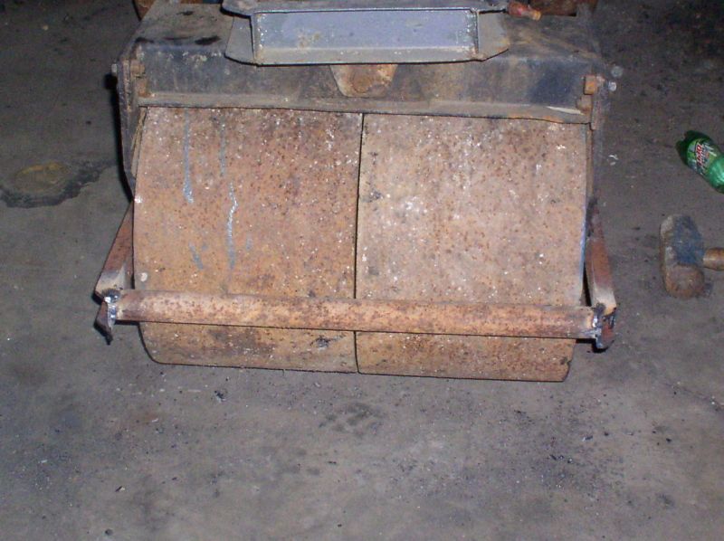
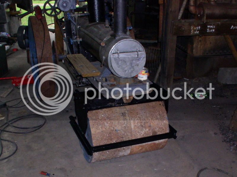
Finally, another mini-update - Today I built the front roll scraper. It may not look like a major project, but it took me almost 4 hours! This is one of those parts that has to be slightly oversized for durability's sake.
The first step was to make the 2 actual scraper bars. Some 1/8" x 2" strap welded to a piece of 1-1/4" pipe. Getting the amperage right so the 6010 rods would neither stick, nor burn through was a bit tricky with the ancient Forney AC box I was using!
Then the 2" channel side brackets were welded to one of the scraper bars.
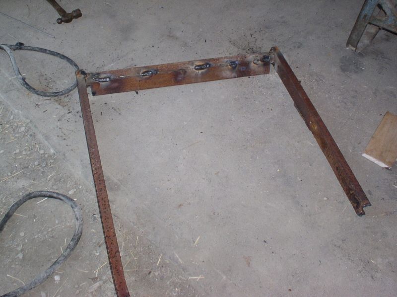
Set in place and welded to the roll bracket
And finally the front scraper bar was welded in place and the sides were cut to length.
By this time I'd lost the light.... again
The first step was to make the 2 actual scraper bars. Some 1/8" x 2" strap welded to a piece of 1-1/4" pipe. Getting the amperage right so the 6010 rods would neither stick, nor burn through was a bit tricky with the ancient Forney AC box I was using!
Then the 2" channel side brackets were welded to one of the scraper bars.
Set in place and welded to the roll bracket
And finally the front scraper bar was welded in place and the sides were cut to length.
By this time I'd lost the light.... again
Allen
Well-Known Member
- Joined
- Jul 14, 2008
- Messages
- 128
- Reaction score
- 55
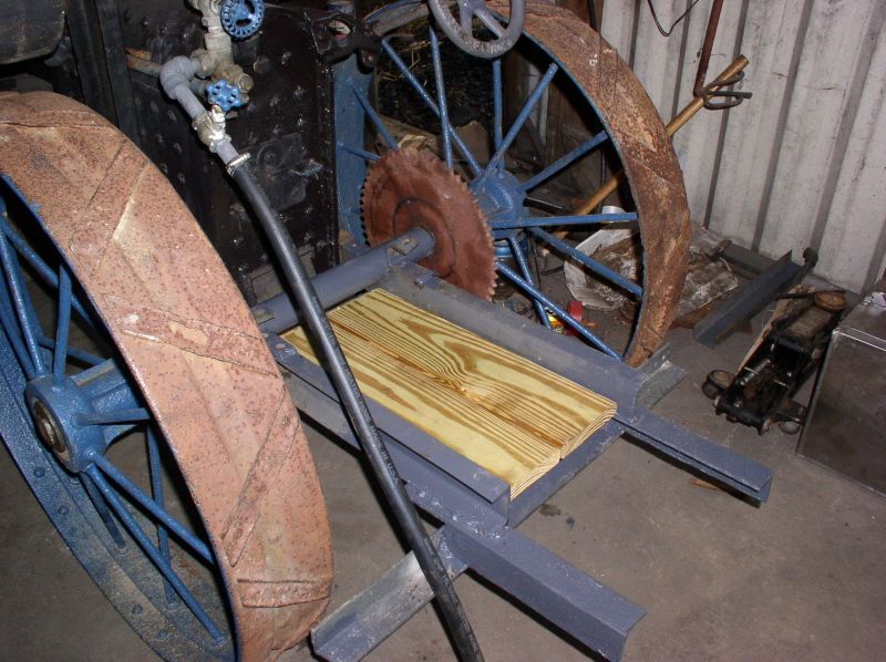
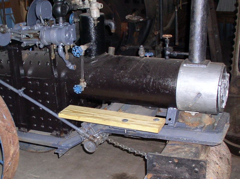
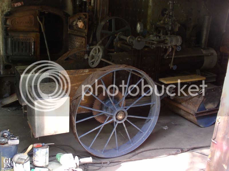
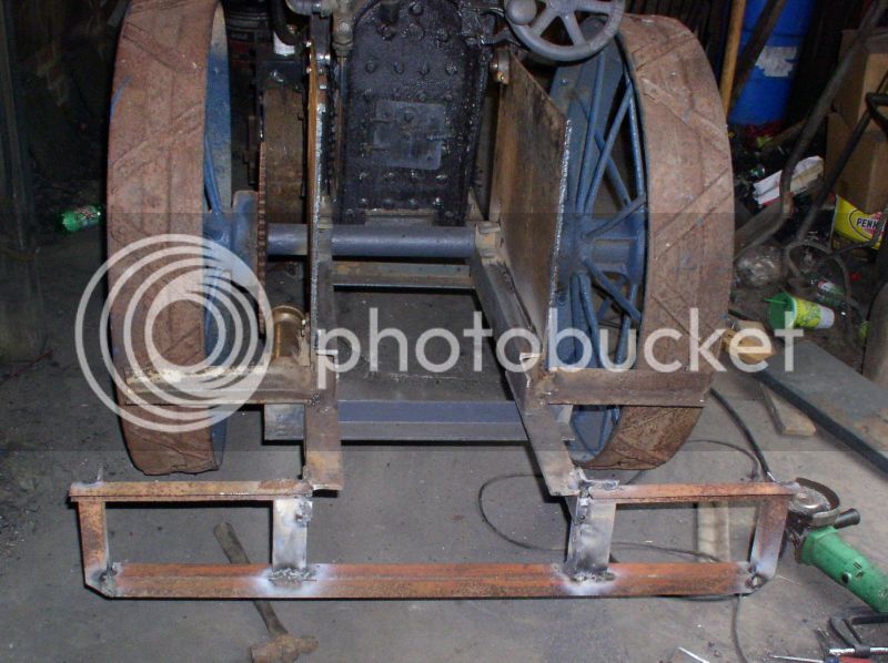
Today was a day to make what looked like a lot of headway just because the pieces were huge. I was looking for 3/16 sheet to make these two platform sides, but I found some 1/4" plate at a really good price. I decided to use solid pieces instead of open bracework for one very good reason - I didn't want kids getting tangled up in the driveline. Since I had good sturdy plate, I decided that the best way to mount the countershaft would be to drill the upper front corner and mount flange bearings. It took me about 2 hours to lay out and drill all the holes. One of them had to be 1-1/2" in diameter to clear the differential (so the chains line up). It was probably a good thing I had access to the machine shop at the showgrounds!
The left side also got the 1-1/2" bore hand pump mounted before getting welded in place.
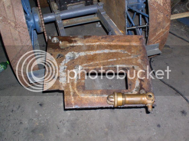
Clamped in place and ready to weld.
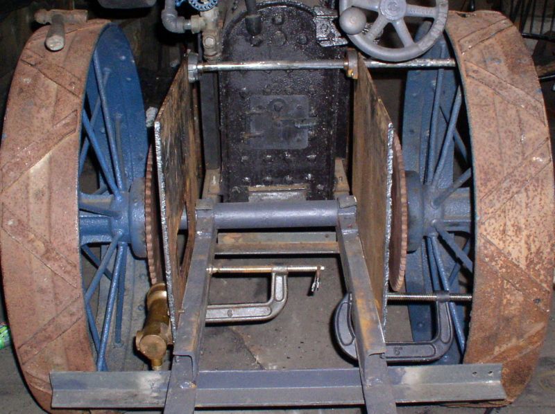
The actual top side welding took about 20 minutes. I'll need to pull the rear wheels to do the lower welds. After that I'll mount the countershaft
The left side also got the 1-1/2" bore hand pump mounted before getting welded in place.
Clamped in place and ready to weld.
The actual top side welding took about 20 minutes. I'll need to pull the rear wheels to do the lower welds. After that I'll mount the countershaft
Allen
Well-Known Member
- Joined
- Jul 14, 2008
- Messages
- 128
- Reaction score
- 55
Yesterday I spent a whole day working on this. Well, more like work a bit, sit and think, spend a goodly while digging around trying to find where you just set down the part you need, sit and rest, err, daydream, err, think again, then work a bit more. Part of the reason I'm on disability is I gotta "think" so much.... I'm like a young old geezer.
A quick mock up of the hotdog cooler bunkers to get an idea of how to proceed..
A start on the support framework - I used up what angle stock I had along... Good thing there's a bit more in the shed.
With the coolers temporarily set back in place it's starting to look real good
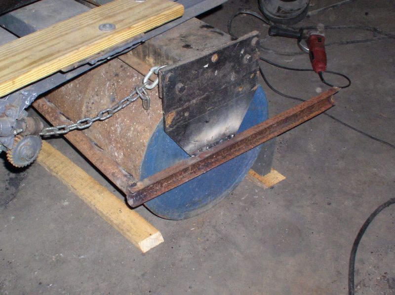
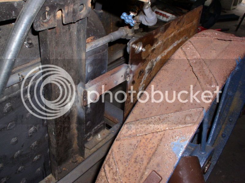
This bit of leftover manure spreader steering axle bracket will perform a very important function... helping to keep the front roll from trying to fold on rough ground
Since it started to thunder I decided the wisest course was to disconnect the welder. So I spent a bit painting the front roll bracket black... Unfortunately, the can of Rustoleum had frozen at some point, so it was kind of like painting with pudding.
After the rain stopped I added this brace made from a leftover short bit from the scraper bracket. I doubted the bearing mounted in the plate is gonna move, but the engine bracket was a different story.
And yes, I also assembled and installed the differential (often referred to as a "compensating gear in the old literature) - good thing I was planning on relocating that injector anyway...
I ran out of light and it was starting to rain again, so that's as far as I got. And today I HURT.
A quick mock up of the hotdog cooler bunkers to get an idea of how to proceed..
A start on the support framework - I used up what angle stock I had along... Good thing there's a bit more in the shed.
With the coolers temporarily set back in place it's starting to look real good
This bit of leftover manure spreader steering axle bracket will perform a very important function... helping to keep the front roll from trying to fold on rough ground
Since it started to thunder I decided the wisest course was to disconnect the welder. So I spent a bit painting the front roll bracket black... Unfortunately, the can of Rustoleum had frozen at some point, so it was kind of like painting with pudding.
After the rain stopped I added this brace made from a leftover short bit from the scraper bracket. I doubted the bearing mounted in the plate is gonna move, but the engine bracket was a different story.
And yes, I also assembled and installed the differential (often referred to as a "compensating gear in the old literature) - good thing I was planning on relocating that injector anyway...
I ran out of light and it was starting to rain again, so that's as far as I got. And today I HURT.
Allen
Well-Known Member
- Joined
- Jul 14, 2008
- Messages
- 128
- Reaction score
- 55
Today was sort of a half day. And I got a lot less done than I wanted to. I probably spent 3 hours plus just trying to re-route the injector lines. Mixing and matching various length pipe nipples to get things to line up. Two are done, leaving just the suction line to figure out... and all the hand pump lines.
I made a bracket for an outboard bearing on the countershaft since I wasn't sure about 3" sticking out unsupported.
Well, the coolers still aren't fastened down, but they are nearly ready to. I need to cut a few bits yet, but all the teeth wore off the sawzall blade I was using.I threw a quick base coat of paint on the rear end even though it isn't finished because I needed to use up the end of the grey.
Once again I ran out of light. Now It'll probably be Friday before I get back to it again.
- Joined
- May 27, 2010
- Messages
- 2,999
- Reaction score
- 1,171
This is a big job.Would love to see it running. Please post updates.
- Joined
- May 27, 2010
- Messages
- 2,999
- Reaction score
- 1,171
This is a big job.Would love to see it running. Please post updates.
Here is mine that nearly look like a steam roller.
Took three months to build and complete.
The steering has yet to done but Mini Tractor Engine can run.

- Joined
- May 27, 2010
- Messages
- 2,999
- Reaction score
- 1,171
Blacksmiths are my heros.Used to watch my neighbour forging knifes,forge welding etc.Their hardening and quenching was so fast
was so fast and I saw nothing and understood nothing. Went to technical college and heat treatment was on the learning list.
Too bad my instructors taught from the book.Workshop instructors were third grade.Singapore was a third country in the 50s and 60s.
Then came the challenge 20 years later and eventually bought heat treat furnace to heat treat die tools.Tool steel salesmen gave some tips and enough reading material and that was about all.There was still so much to learn. Quenching Oil------Fast-----Medium-----Slow.You cannot quench carbon steel in oil. Some tool steels cannot be quenched in water.
Allen
Well-Known Member
- Joined
- Jul 14, 2008
- Messages
- 128
- Reaction score
- 55
Biggish update! I got a lot of weird little things done, some I have pix of, some didn't come out.
One that the pic didn't come out was the exhaust piping inside the smokebox. It was pretty much a 3 handed job with room for none. Things got really interesting when the stupid channel locks slipped, hit the trouble light and sprayed broken glass and sparks in my face... there's a REASON I always get polycarb lenses!
If you remember the test fire from 2010, then you'll recall this boiler doesn't draw worth a hoot (it was originally designed for an undermounted, with the typical short chimney) So in order to help the boiler draft better I decided I needed to lengthen the stack.... Just how tall was the question. The piece I had to splice on was just a LITTLE BIT too long
I cut it off the same height as the top of the governor. But it still wasn't right. (A spark arrestor will be made from this wing fryer basket I found at a flea market for 50c, more on that in a day or three)
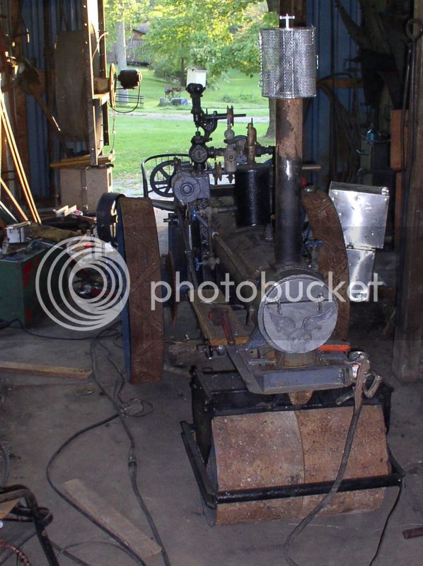
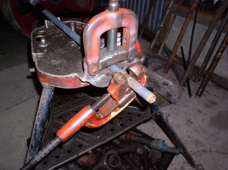
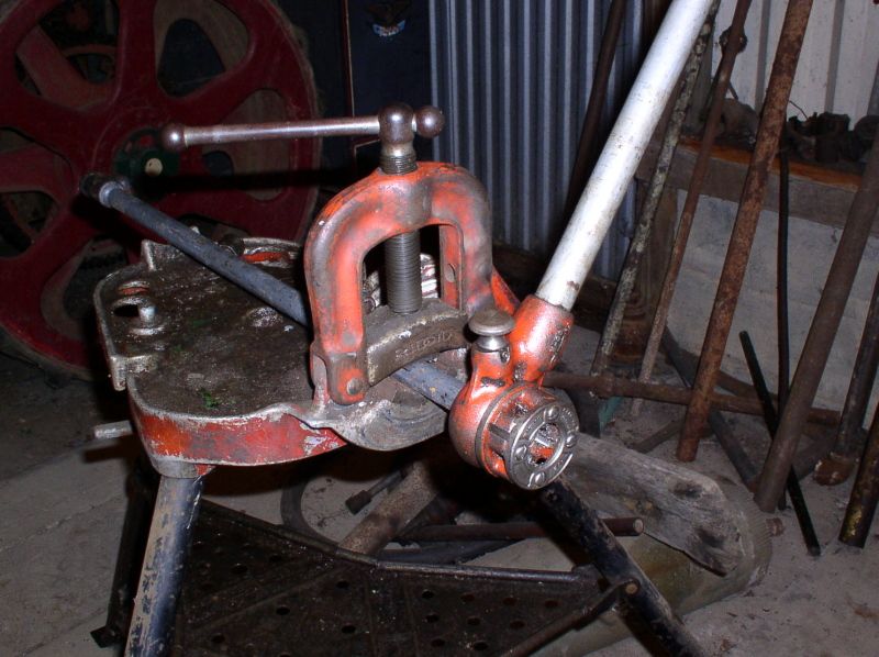
So I tried once again, this time I think it looks acceptable. If you've ever used little Ridgid pipe cutters to do household plumbing, here's one on steroids... It will cut up to 6"
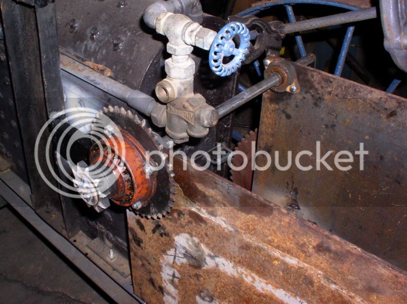
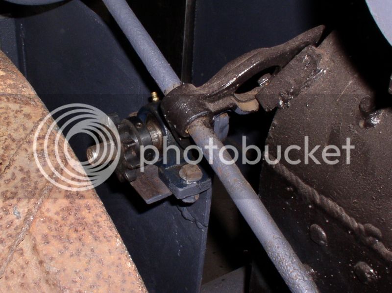
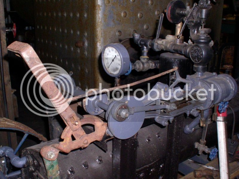
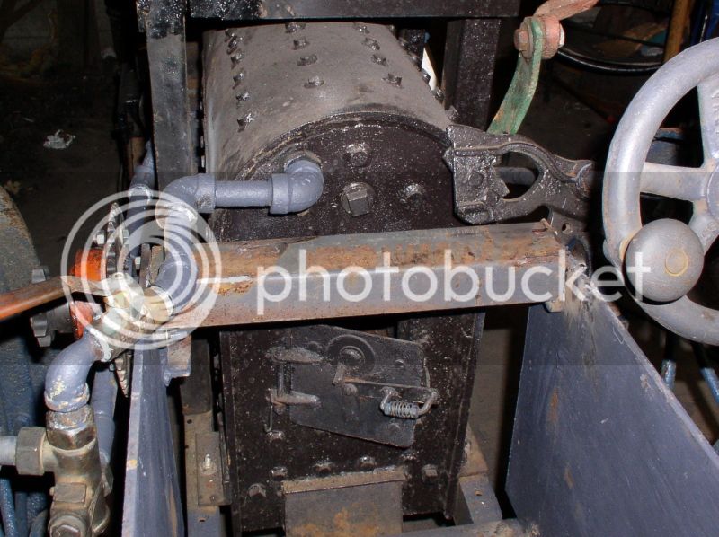
On to something interesting. I got this lever off the same manure spreader the wheels came from. It will make a dandy Johnson bar.
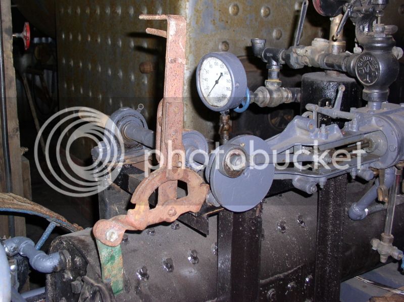
And hooked up. The notches for forward and reverse are only about an inch apart.
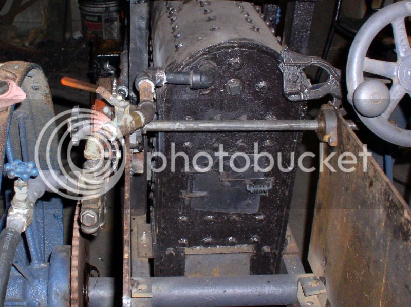
Some very light used 3" channel made a good looking countershaft shield
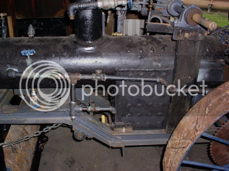
Then I worked on the feedwater piping some more, but didn't take a pic
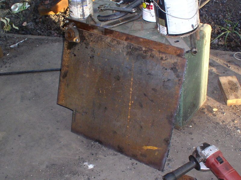
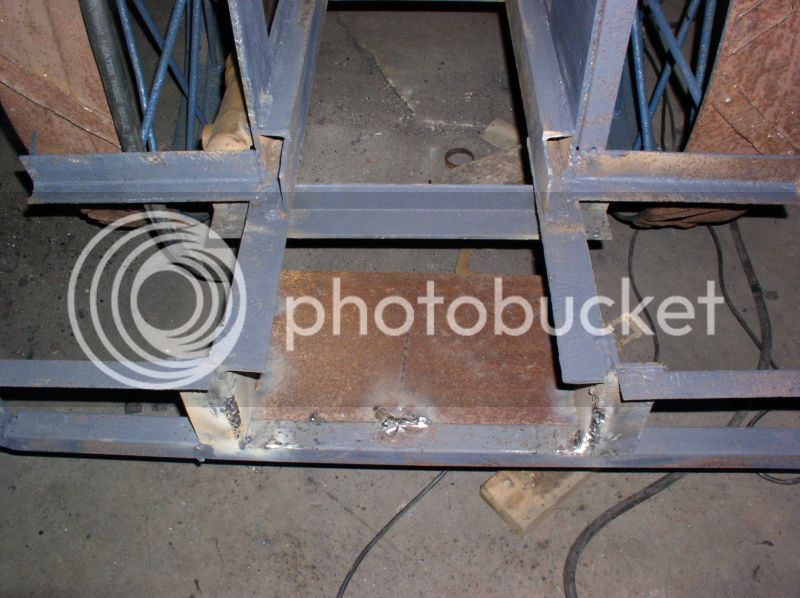
I thought long and hard about how to do the depressed section of the platform. I really wanted to use 5/4 wolmanized like the upper platform, but also needed to make the whole thing strong enough to be used as a tie down point when the roller gets trailered. Well, I had this bit of diamond plate seasoning in the shed, so I decided to go the lazy route and just use it to make the depressed section. I may bolt wood to it later.
The bunker supports are done. They hold my weight without moving. I need to get a couple bulkhead connectors yet, before I mount the hotdog coolers, but I'm actually pleased with how it looks so far.
I had to quit early because I had a meeting, so that's all for this update. thanks for looking!
One that the pic didn't come out was the exhaust piping inside the smokebox. It was pretty much a 3 handed job with room for none. Things got really interesting when the stupid channel locks slipped, hit the trouble light and sprayed broken glass and sparks in my face... there's a REASON I always get polycarb lenses!
If you remember the test fire from 2010, then you'll recall this boiler doesn't draw worth a hoot (it was originally designed for an undermounted, with the typical short chimney) So in order to help the boiler draft better I decided I needed to lengthen the stack.... Just how tall was the question. The piece I had to splice on was just a LITTLE BIT too long
I cut it off the same height as the top of the governor. But it still wasn't right. (A spark arrestor will be made from this wing fryer basket I found at a flea market for 50c, more on that in a day or three)
So I tried once again, this time I think it looks acceptable. If you've ever used little Ridgid pipe cutters to do household plumbing, here's one on steroids... It will cut up to 6"
On to something interesting. I got this lever off the same manure spreader the wheels came from. It will make a dandy Johnson bar.
And hooked up. The notches for forward and reverse are only about an inch apart.
Some very light used 3" channel made a good looking countershaft shield
Then I worked on the feedwater piping some more, but didn't take a pic
I thought long and hard about how to do the depressed section of the platform. I really wanted to use 5/4 wolmanized like the upper platform, but also needed to make the whole thing strong enough to be used as a tie down point when the roller gets trailered. Well, I had this bit of diamond plate seasoning in the shed, so I decided to go the lazy route and just use it to make the depressed section. I may bolt wood to it later.
The bunker supports are done. They hold my weight without moving. I need to get a couple bulkhead connectors yet, before I mount the hotdog coolers, but I'm actually pleased with how it looks so far.
I had to quit early because I had a meeting, so that's all for this update. thanks for looking!