Mike Pileski Vertical Engine build .....

Home Model Engine Machinist Forum

Help Support Home Model Engine Machinist Forum:

This site may earn a commission from merchant affiliate links, including eBay, Amazon, and others.

toolznthings

Project of the Month Winner
Joined
Dec 11, 2013
Messages
259
Reaction score
183
Location
Ohio
Hi All,

Kind of doing this backwards. I just finished the vertical engine design by Mike Pileski published in Steam & Stirling Book # 3. I find it easier to document and finish and then post the results. Other than some material changes and some construction changes very little was modified. The engine is a 1.500 bore x 1.500 stroke and mine will run on air. Overall height is approximately eleven inches high.
So here goes .... I'll start with the cylinder.

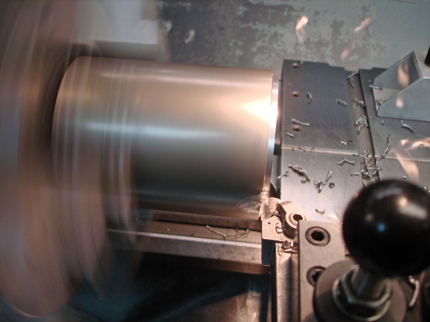
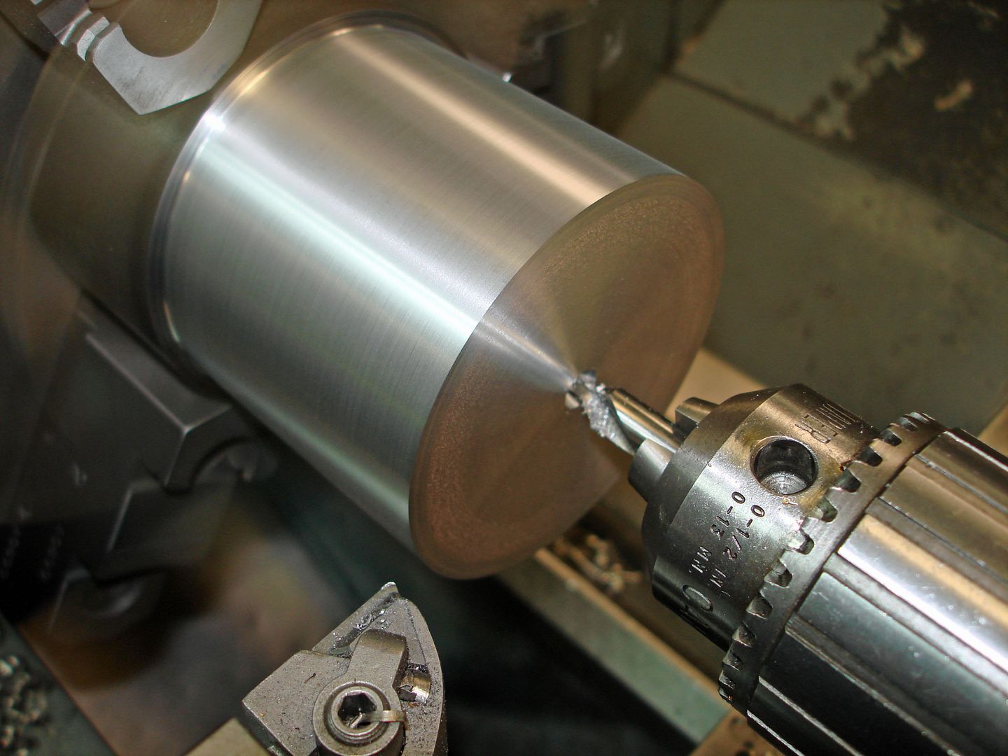
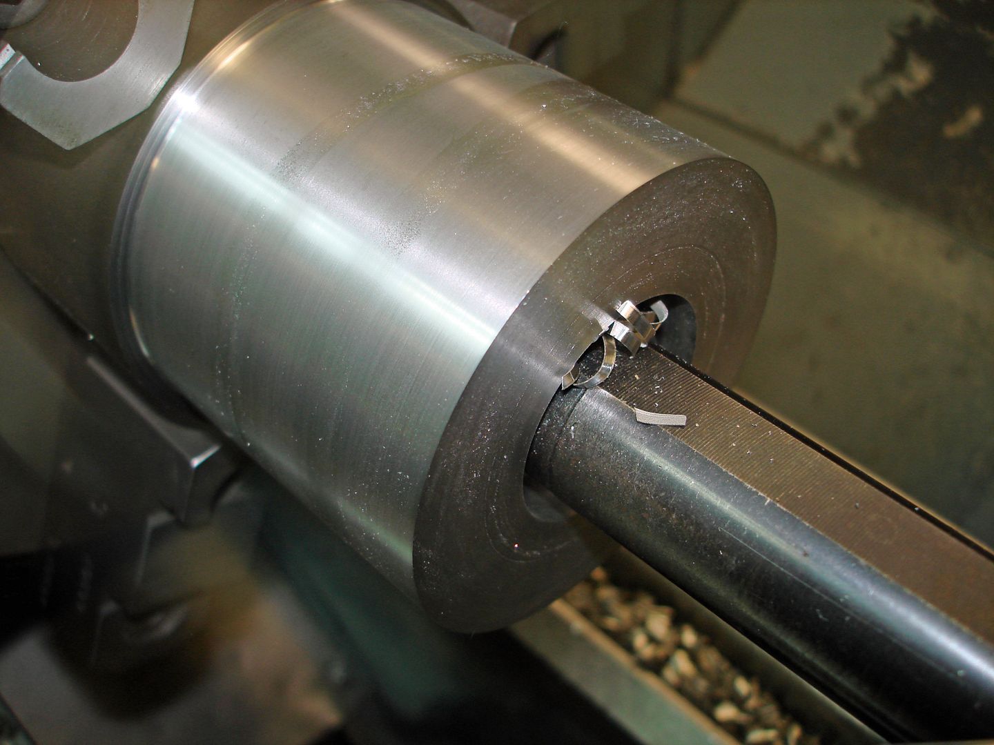
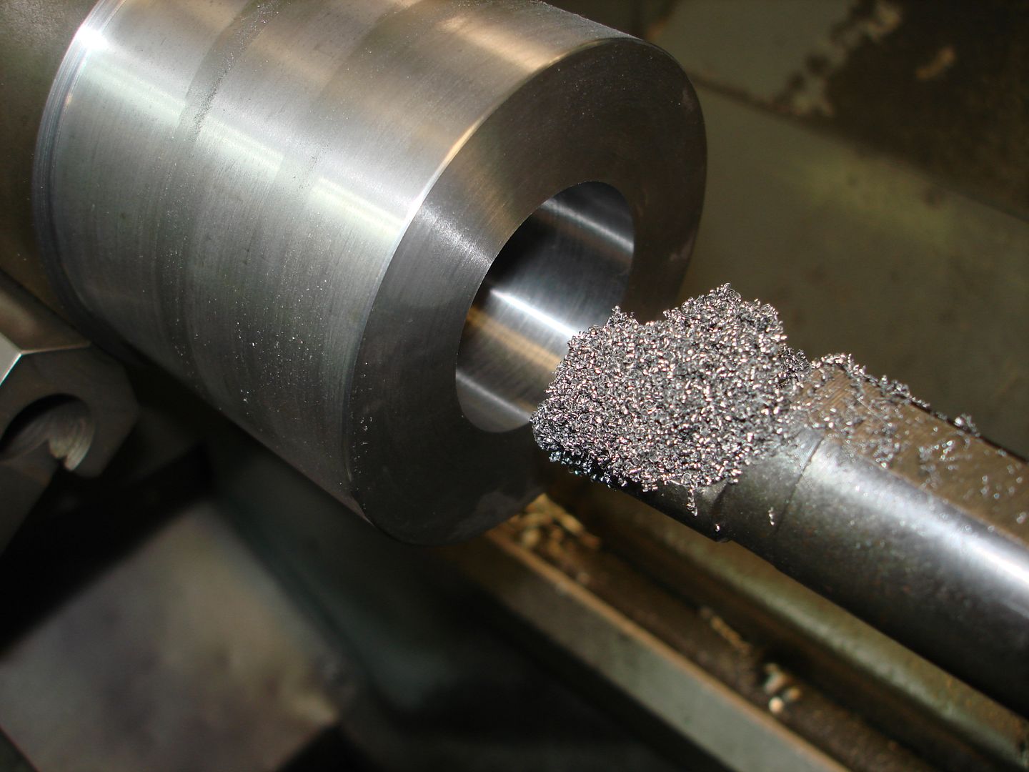
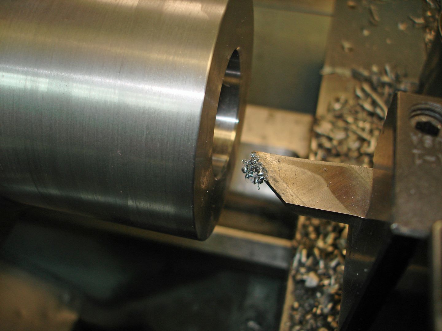
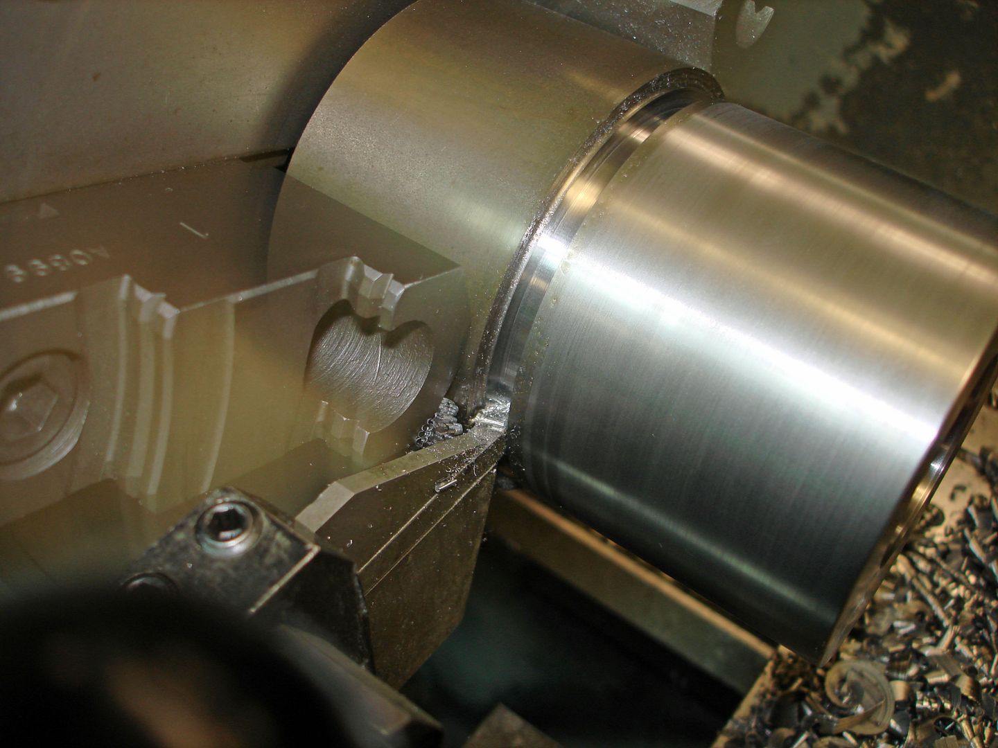
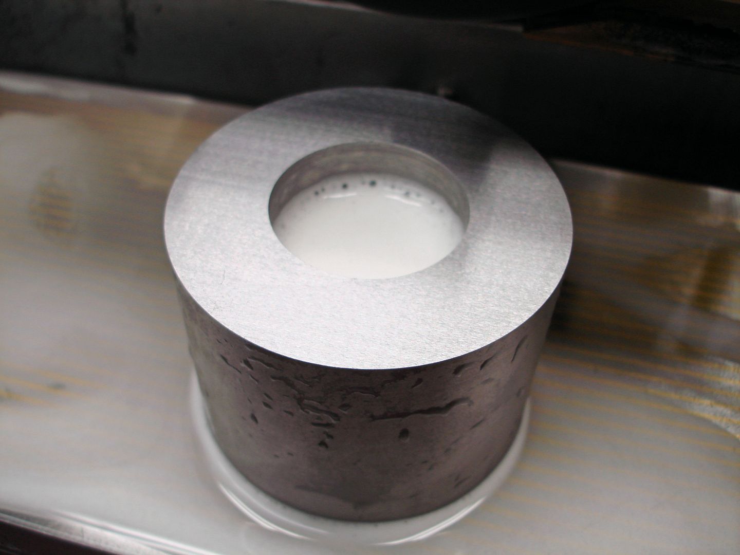
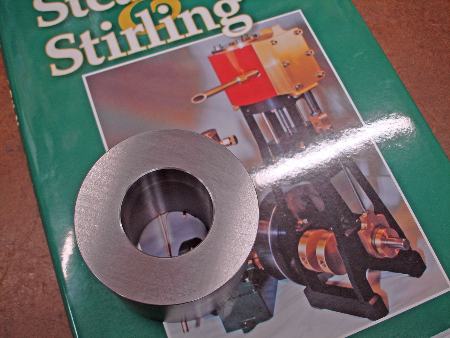
Turned the 3" diameter from 3 1/4" diameter 12L14 and faced one end. Center drilled and rough drilled. Bored and chamfered then polished the 1.500 bore. Parted off the stock leaving some grind stock on the overall finished length.


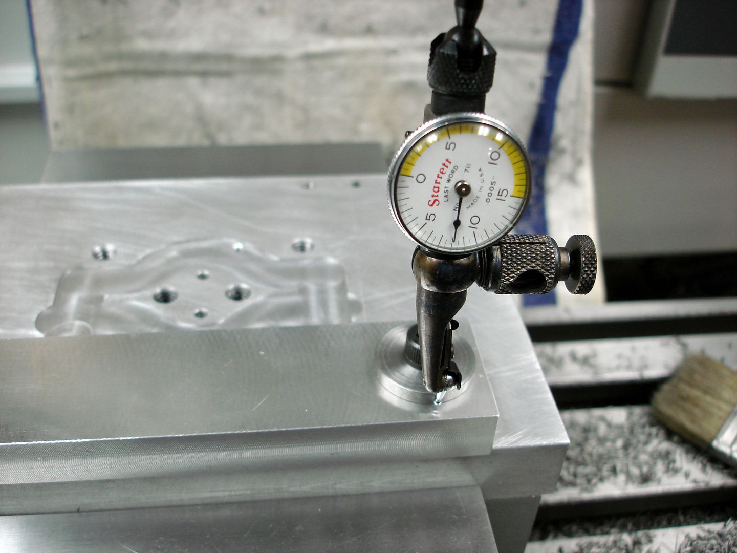
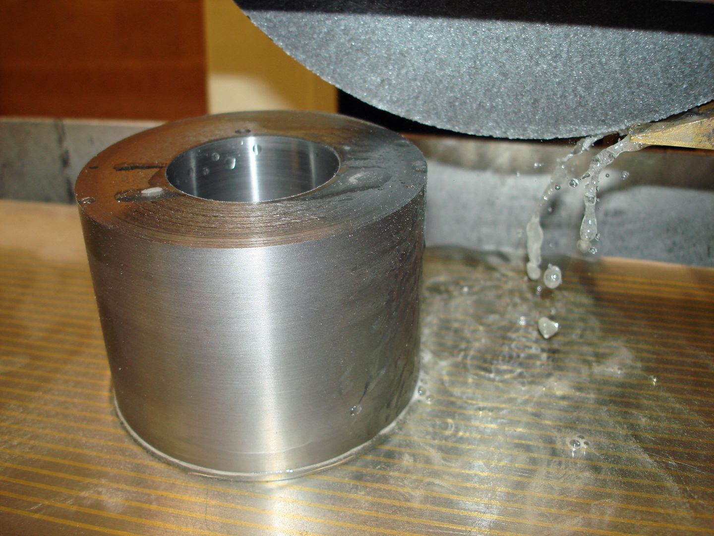
Next operation is at the surface grinder. I set up on the face that was done with the bore in the first operation and ground the opposite side first. This will insure that I will be perpendicular to the bore. Turned cylinder over and finished the overall length.


More build to come ......
 
Brian-Hey finally got in here!
It's really nice to see my design being built by someone, and such a fine job at that. I look forward to all of the build photos.

Mike "Sid" Pileski
 
Next step in the cylinder machining will be the flat for the steam chest and valve ports. Since I had 12L14 material on hand I took a chance on finishing the cylinder bore before cutting the flat. 1144 stress proof would have been my first choice if I had stock on hand. In the end the bore only went out of round about .0015" after machining the flat. Finishing the bore size after the flat would have been less risky. I milled the flat leaving grind stock.


The next setup was in a precision vise on the granite plate using a indicator to set the part true to the milled flat.


Then to the surface grinder to finish to size.


Back to the mill to start finishing some of the details. I now have accurate surfaces to work from. I set the part face down on the valve surface to add the two tapped holes for the steam valves with spot faces.


The next setup was for the milled air slots.
I indicated the bore to find center and milled the two air slots at the top and then setup for the bottom. The mill stop on the side allowed for turning the part over.


With the same settings I did the tapped holes for the cylinder top and bottom covers.


Another setup to counter bore, drill and tap for the exhaust port.


I setup for the three port slots to be milled where the slide valve will operate.
Indicating the flat true to the mill table.


Milled the three slots to depth.


With this same setup I drill and tapped for the steam chest. Not shown, but later on I added two 4-40 tapped holes in the cylinder and matching drilled and counter bored holes in the steam chest to separately bolt the chest to the cylinder to keep it in place with out the having the cover plate and bolts installed.


That completes all the holes except for the angled holes from the cylinder slots to the valve slots.
 
Using a tilt table and small vise I made a set up to hold the cylinder. I used a mill clamp and 1-2-3 blocks to set a stop against the cylinder so the cylinder can be removed and set back in position.


With the table set at zero the bore was dialed in to find x-y center on the bore.
The cylinder was then removed from the set up and a small strip of aluminum
was wedged in place across the bore and flush with the cylinder end. It is important to be sure the strip of aluminum is flush with face of the cylinder. At the surface plate a scribed line was made at the exact center height of the bore.


Back to the mill and in the vise the table was tilted to 25 degrees. Our original " Y " position has been maintained , but we need to find our new " X " position using a wiggler that has been trued. Picking up the scribed line at the surface e and setting zero for "X". To maintain accuracy the wiggler point needs to be as close as possible to the surface where the line is scribed.


Using a CAD layout I new the distance I needed to move in "X" to be in position to drill the air passage to the first top slot in the valve face.

A check for position with the wiggler.


Spotting a flat with a end mill was first operation.


Then center drilling and finally drilling the hole. With the stop set against the cylinder the opposite side was done after flipping the part over with the same settings.


The completed cylinder.

 
Hi Ron,

The extra slot is for two, what I call, blow down valves if you run the engine on steam. Lets you remove condensation from the cylinder. Although I will be using air, I'm trying to keep the design going as presented by the author. Later in the build you will see what I did with this feature.( back track a few pics and you can see where the valve holes are being tapped )

Brian
 
Last edited:
I decided to do some changes on the crank shaft build. The throws will be machine as one piece and the crank will be made so it can be disassembled.
The wrist pin will be made from a standard hardened .500 dowel pin.

The first operation will be machining the ends of the dowel pin. I choose a dowel pin so the needle bearing will ride on a hardened surface. A carbide insert will cut through the hard dowel pin surface. The core of the pin is softer. Wore out two insert edges to do the machining. Tough for sure, but doable. The overall length was rough cut with a carbide parting tool and finished faced before turning the last diameter.


I held the finished diameters to a tight tolerance so the assembly will be as accurate as possible.

Views of the wrist pin before parting off and facing to length ....


The finished wrist pin ....


The crank throws were the next operation. Starting with stock thicker than the final .375 finished dimensions I bored the holes for the wrist pin and crank shafts. Boring gives me the best hole for fit and will be perpendicular to the faces of the throws. The blanks for the throws were machined accurately and sized larger for stock. One face of the blank was surface ground.


The next setup will be at the CNC mill to do the outside contour of the throws at a depth slightly deeper than the finished thickness. Part zero of the program was set off the bored holes from the manual operation on the blank.


Finished contours with excess material band sawed from around the contour ....


Back to the manual mill to machine off the excess stock that was used to hold the throws for machining at the CNC mill. Grind stock was left on this face.


Next operation was at the surface grinder to finish the final thickness parallel to the first surface.


The throws were then setup to saw cut through to the wrist pin bores and to drill, counter bore and tap for socket head cap screws.


The set up for the drilling / counter boring ....


The crank main shafts were Loctited in place and at final assembly were pinned to the throws with # 3/0 tapper pins.

The finished parts ....


Pictures of the crank assembly with the bearings ....


Assembled and complete ....

 
With that steel cylinder, wouldn't rust be a problem if this engine is ever run on steam? I personally would have used stainless for the cylinder if I was building this engine.
 
Hi,

As far as I know all old steam engines used cast iron for cylinders. I'm no expert, but the Triple Expansion engine on the converted Liberty ship I was on in the Navy was all cast iron with rings as well as other supporting stem equipment. A water soluble oil is injected into the engines big or small. The engine that I'm building will never run on steam and even with that in mind I will add some lubrication oil to the cylinder now and then. Maybe some other members more knowledgeable on the subject can add some input.
Thanks for the input !

Brian
 
Next part will be the connecting rod. Starting with a 6061-T6 aluminum blank
machined to the thickest dimension of the rod and with stock for machining the outside contour. First operation is to bore for the crank end bearing and the wrist pin bearing.

Rough drilled for each bore first then the boring operation ....


Finished bores with two set up plugs for CNC milling the contour ....


The two plugs shown in the previous picture will be used on the sacrificial fixture plate to locate the rod and provide a indicating reference to the finished bores and clamp the blank.


Setting part zero ...

DSC00064.jpg


Milling the outside contour of the connecting rod ....


With the same set up I machined the circular boss around the crank end of the rod on both sides ....


Back to the manual mill with the fixture to machine the thickness of the rod at the wrist pin end up to the clamping screw. Doing both sides.


Removed from the fixture and held in the vise I finished the last part of the rod thickness.


The finished rod with the needle bearings installed. The wrist pin bearing is wider than the plans called out. It was what was easily available at the time.


The cross head machining ....

The cross head contour was machined at the CNC mill from a longer blank so it could be held in the vise. The wrist pin hole was done at the manual mill and was indicated at the CNC mill for part zero.


The finished end was band sawed from the longer blank and finished milled at the manual mill.


The holes for the bronze bearings were bored and 2-56 threaded holes were added later to secure the bearings.


The slot for the wrist pin end was machined to width to match the wrist pin bearing. Not shown, the 1/4-28 tapped hole for the piston rod was also done in this setup along with a set screw tapped hole to secure the wrist pin.
I will be using a .250 diameter hardened dowel pin for the wrist pin.


Using a corner rounding mill the corners of the cross head were finished ...


The finished rod and cross head assembly ...


Starting again. All my posts from yesterday disappeared.:mad:

Setting up to prep side plates for machining at the cnc mill. Rough sawed contours and set up on a piece of mdf board to add fixture holes and finish crank shaft bearing bores.


Using my cad layout printed on transparency film I picked a spot on the fixture plate to add the needed tapped holes. Realized I forgot one hole, so back to the manual mill.


Clamped to fixture plate after picking up bearing bore for part zero. There are two 1/8 dowel pins that provide location. Milling the outside contour first.


Cutting the thru pockets in separate programs and clamping were needed between operations.


The finished plate.


Set up at the manual mill in pairs to add the bottom tapped holes.


Fixture a blank to machine the cross support. Machining the outside contour first.


Clamping the outside to finish the thru pocket inside contour.


Set up at manual mill to add the cross head guide rod holes and set screw holes for the rods.


Adding the tapped holes for the side plate connection.


Cylinder bottom machining at the lathe. Turned o.d. and 1.500 diameter step and the piston rod bore in the same set up before parting off.


Soft jaw chucked and finished the thickness and the bore for the packing gland.


At the mill to add the necessary tapped holes after finishing the milling operations plus the guide rod holes for the cross head.


The finished cylinder bottom with the cross piece.


I had no brass material available so I decided to make the steam chest from steel.
I squared up the overall size first and set up to drilled and reamed the corners of the inside cut out.


Using a larger end mill to rough out the bulk of the material. Then finished the sides with a .250 size end mill.


Set up to mill the end contour of the steam chest.


Drilling the mounting holes to match the cylinder. Later on at final assembly I added two 4-40 counter bored holes in the steam chest and added matching tapped holes in the cylinder. This would allow the steam chest to be mounted without the cover plate. This aided in the valve timing

.

Drilled and reamed for the valve rod. Not shown are the valve gland bolt holes or the packing gland counter bore.


Passed a long center drill thru to spot for the blind hole for the valve rod. Then drilled and reamed.


Later on in the build I made the same set up to drill thru and ream and add a closed end bronze bushing for the end of the valve rod to ride in rather than steel on steel. The air inlet hole was drilled and tapped, also.

Steam chest finished.


Machining parts for the valve assembly. Starting with the eccentric carrier sleeve that slides on the crank shaft and will carry the eccentric. Turned the o.d. diameters and boring to fit the crank shaft journal. A set screw will be added at the larger diameter to lock the sleeve to the crank and allow for valve timing.


The finished sleeve ready for a setup on the rotary table to mill the slot for the eccentric 1/8" pin.


Setting up with a longer piece of stock at the mill to do the eccentric bore to fit the sleeve and add the dowel pin hole. Indicating to center the stock with the mill spindle.


Doing the bore first. Used a .500 end mill to finish the bore. Offset in " Y "
to do the .125 dowel pin hole. Reamed to have press fit on pin.


Cut off from the longer stock and finish faced to length at the lathe ...


Made a blank from brass for the eccentric follower and bored the thru hole at the manual mill. Used a plotted overlay to find center for the bore leaving stock for the outside contour.


Made a clamping / indicating bushing to do the outside contour at the cnc mill.
Clamped to a fixture plate and indicated for part zero.


Finished milled eccentric follower.


At the manual mill I added the tapped hole for the push rod and added a small thru hole for oil. Not shown is the brass collar which holds the the eccentric follower on the carrier sleeve.

Squared up a piece of bronze and started to mill the pocket that covers / uncovers the ports on the cylinder.


On the opposite side milled for the valve adjuster block and spring retainer.
Using a ball end mill to cut clearance for the .187 diameter valve rod.


The valve with the springs and steel adjuster block that the valve rod goes thru. There is a set screw in the block and a flat on the vlave rod for this adjustment.

 
Decided to change the shape of the two packing glands. Two blanks were turned from brass and the fixture block was made to hold and locate the center of each part. Set up at the cnc mill for machining the outside and drilling the mounting holes.


Machined and drilled to finish.


I like the look of the " blow down " valves on the engine, but really did not want to purchase valves that wound not be used so I made some " fake " valves.:D
I made a cad drawing of what I thought would look good and created a cnc program to machine a form tool on the cnc mill. Made from oil hardening flat stock and hardened. Ground some rake on the top after heat treating and set up
at the lathe to plunge cut the valve body shape.


After this operation the thread diameter was turned and single point threaded. I used 1/4-28 threads in the cylinder instead of 1/4-32 which would have fit the commercially bought model valves. Also, the valve end diameter was turned before threading.


I wanted the valve handles to turn so I drilled and reamed the valve body at the manual mill with a # 3/0 taper pin reamer. Using some long 3/0 taper pins I determined where to cut the length when inserted in the valve body and used a die to cut 5-40 threads on the end of the taper pin.
A scrap block of brass was reamed to fit the valve stem and the taper pin was heated to bend at 90 degrees.


To finish the valve the handles were cut to length, small brass washers were made and the valve bodies had a hole drilled in the discharge end to finish the look. A drop of small thread locker was used on the nut holding in the valve stem.


The finished look of the valve.

 
Very impressive work Thm:Thm:
were are plans available for this motor ?
cheers
Luc
 
Hello,

I found the plans in the books shown for sale in HSM magazine in the back.
It's title is : Steam & Sterling Engines You can Build Book # 3
It's a compilation of different builds which I assume were originally published
in Live Steam magazine. ( a guess )

And Thanks for the comments ! To all !!
Brian
 
Machining the base blocks / cross brackets that hold the uprights in pairs from flat ground bar stock. Milled the overall length first then set up to machine the side plate slots to fit their thickness. With this setup center drilled and drilled thru for the mounting holes and milled the end chamfers. Had a stop set to the left of the parts for the next operation.


Drilled thru and clamped the the two parts together and turned over to counter bore for the socket head screws and add a 10-32 tapped hole for mounting the engine to a display stand. Up against the stop to maintain original location.


The finished parts ...


Machining the flywheel with a change from the original design by extending the thickness for a hub for a place to add a mounting set screw. Turned the o.d. in a separate operation and held the blank in soft jaws to rough turn the hub side first and then finish the thru bore.


After boring I used a round nose tool to cut the dished face on the flywheel and the hub diameter. Turned part around and performed the same operation on the back side.


Set up at the mill to find the bore center and add a 10-32 tapped hole for holding the flywheel to the crank shaft. I machined a spot face in the crank for the set screw.


Some finish polishing and some paint and the finished flywheel ...


Latest posts

Back
Top