Liney Halo

Home Model Engine Machinist Forum

Help Support Home Model Engine Machinist Forum:

This site may earn a commission from merchant affiliate links, including eBay, Amazon, and others.
After a 4-day weekend offroading the Jeep and 3 more days doing various maintenance work, I finally had an afternoon in the shop to get back to the engine.

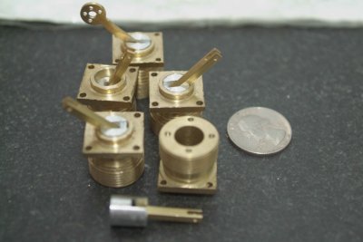
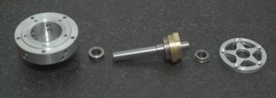
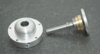
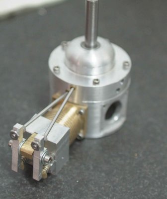
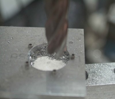
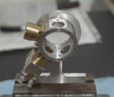
First I finished all of the remaining drilling on the 4 headers (I will need to remake the 5th). Then I put one of them together completely along with the cylinder. Here's a looksee:

large.jpg


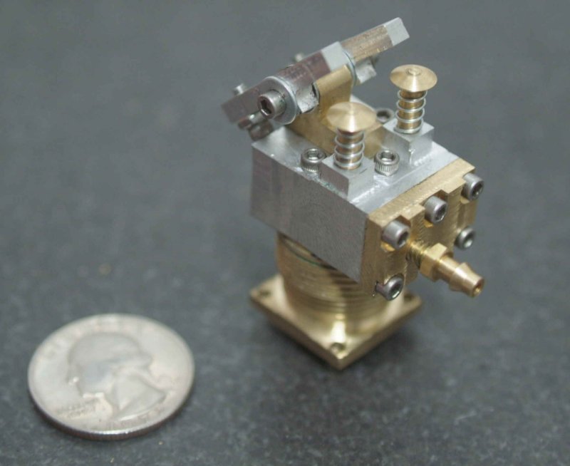
Originally I was going to leave the valve cover thicker than the plans, as I had made them from .25" thick brass plate. However, I needed to attach them with the shortest screws, so the options were to machine them thinner or cut the counterbores deeper. FWIW, I milled the counterbores with a 3/16" endmill; the plans show using a 1/8" endmill, but since the head of the screw is larger than that milling the bores is more complicated/tedious.

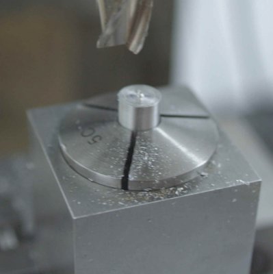
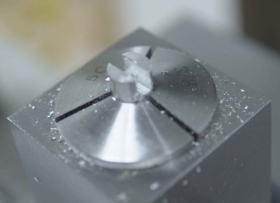
Some of the brass plungers were a bit too large to fit the holes, even though I measured them at .125" and the holes were reamed with a .126" reamer. Once they're machined they are a PITA to hold and polish down to size (I used a needlenose plier). So a recommended alternative would be to make the heads first and test for fit on the lathe before parting off and machining the heads.

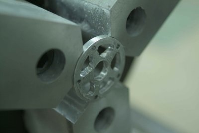
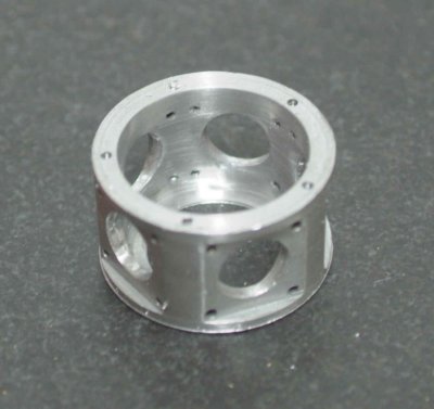
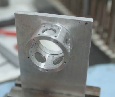
Next step is to clean up the interiors of the cam housing and crankcase, plus part off the crankcase and make some pistons. Then it will be time for a trial assembly. I also need to start thinking of a mount design.

Now to put the cat amongst the pidgeons. Correct me if I'm wrong, but with the cam proflie being what it is, it looks to be an easy job to add another 4 cylinders and turn it into a 9. If you are making 5 cyclinders , not much extra time for another 4. Once I start will make a 5 and a 9. Geoff

It doesn't sound that easy to me. The dimensions of the crankcase allow space for only 5, so a 9 cylinder model needs smaller cylinders or a larger crankcase. If you are good with cad/cam software then I suppose getting the correct dimensions would be doable.

How about 10 cylinders...

If you made two 5-cylinder engines and connected them back to back with a common crankshaft then most of the dimensions would remain the same. However, I don't think that would be as attractive as the piston rods and cams would then be hidden from view. Unless the crankcases were made of lucite. ;D
 
this is a very nice piece of work kvom!

1 of 5 done! go kvom go :)
 
Looks really good, Kvom. Really good. Seeing it put together as a complete assembly really shows off all your hard work, (and skills)!

Dean
 
I had another full afternoon in the shop. Today I started with the pistons. Chucking some 1/2" diameter aluminum rod, for each I turned 1/2" length down to .375 and individually fitted each to its own piston, trying to attain a rough sliding fit. Then I parted each off,

To finish a piston, I chucked it in a 5C collet block with .25" exposed, then placed the block vertically in the mill vise. I used an edge finder the first time to find the center. First operation was to mill off the nub from parting and bring to length.

medium.jpg


Then with a 1/8" endmill (1/16" for the master piston) I cut a slot .200" deep, then widened the slot .003" on each side with two more passes.

medium.jpg


Then it was a simple matter to chuck the collet block horizontally and spot drill/drill the cross hole for the wrist pin. Once removed from the collet and deburred, I was able to assemble the conrods to the pistons using the pins supplied by Liney. The holes are not a press fit, but I doubt that's critical. Here's a "family" portrait:

medium.jpg


The pistons still need a bit of toothpaste lapping to slide smoothly. I didn;t cut any oil grooves but I did chamfer the tops of the pistons.

After smoothing the inside of the cam housing with Scotchbrite, I wanted to do a trial assembly of the front portion of the engine. The first task was to machine the bearing carrier to its planned thickness of .125". I had previously parted it off oversize and needed to removed .016" from the back. To do this I decided to use my "new" chuck with soft jaws on the lathe. I had made the jaws over a month previously, but this was the first opportunity to try it.

First, I machined a pocket .100" deep and 1.275" in diameter to match the part. This allowed me to then chuck the disc securely and take the facing cut:

medium.jpg


Now after deburring, I laid out the components for assembly:

Cam housing, front bearing, driveshaft, rear bearing, and bearing carrier:

medium.jpg


The rear bearing is a tight fit to the bearing carrier:

medium.jpg


Then screw the bearing carrier to the cam housing to complete the assembly:

medium.jpg


It's important that the bearing carrier press both bearing firmly against the driveshaft to eliminate any slack but not so that the "preload" causes binding. I need to do some tweaking here. I also noticed a few more issues to fiddle with.

1) The plunger holes are slightly too small for the supplied ball bearings to slide freely, so may need deburring or mild filing.

2) The rear cam seems a bit too far forward and may be interfering with the front plungers. I may need to add a shim.

3) The crank is not sitting perfectly straight on the end of the shaft. I suspect the counterbore bottom is not flat. In any case, the thickness of the crank or depth of the counterbore can be modified to center the conrods under the cylinders, so I will hold off until I'm ready to fit the crankcase.
 
I had a couple of hours before the Halloween visitors start arriving to tweak the cam housing issues.

I discovered upon inspection that the front cam was not seating flat against the driveshaft flange. With tight tolerances on all the parts, the clearance holes were not large enough to allow the screws to enter perfectly straight. I drilled them out with a #43 drill as opposed to the original #42, and with some careful tightening both cams set flush.

Since the camming surfaces are so close to the inner diameter of the cam housing, it's important that the shaft and cams be as perfectly centered as possible. How the bearing carrier is screwed to the housing is important, as it seems that the slightest cant in the carrier can cause the cams to rub. So tightening the screws evenly all around going in circles was necessary. I marked both the carrier and housing to ensure that any reassembly matches up the same set of holes. When assembled, the bearing preload seems good, so I don't think any adjustment will be needed.

I cleaned up the pushrod holes, and now the supplied ball bearings and my brass pushrods fit nicely.

I also parted off the crankcase and turned the back flush, so that I can start thinking how to build a base.

medium.jpg
 
Got into the shop around noon, and decided to verify that the pushrods would correctly activate the rocker arms and valves as designed. The pushrods are just 1/16" drillrod 1.4" long, so I cut off a couple with wire cutters and filed the ends. Here's the assembly with one cylinder:

medium.jpg


It seems to work! At least the plungers that activate the valves go up and down. It takes a fair amount of force to turn the shaft with just fingers. As Liney suggestes, I will need to attach a small chuck or the equivalent to turn it manually with all 5 cylinders mounted. I may need fewer turns on the springs as well.

Given that assembling further without something to hold the engine securely would be difficult, I spent the rest of the session making the first part of an engine mount. First, I took the piece of aluminum from which I parted the crankcase, faced it on the lathe, and then drilled and tapped 5 holes to match the rear mounting surface of the crankcase.

medium.jpg


Next, I found a piece of aluminum plate that had a hole in a useable spot, and with the aid of a little trig and the DRO, I drilled holes to match the jig.

medium.jpg


Then after enlarging the hole a bit on the mill, I mounted the plate on the jig...

medium.jpg


... and milled the hole to match the innder diameter of the crankcase.

medium.jpg


Successful test fit:

medium.jpg


Some more milling, flycutting, on the rotab and vise yielded this:

medium.jpg


A test fit of the crankcase and a couple of cylinders to show that there is clearance for air supply:

medium.jpg


I won't be able to complete the mount until I get a propeller and determine the necessary height above the base, but this part will be very useful in assembling and testing.

 
Things are looking better all the time, Kvom. I like how the crankcase, cam housing, and bearing carrier (star shaped part) came out. They look very "aero", if you get my meaning. Thanks for the progress updates. I really like the appearance of this engine, and following your work.

Keep up the good work, etc!

Dean
 

Nice work.

I love the sound this engine makes.
 
Not much time to work on it today. I decided to mount all of the cylinders and see what it takes to get the pistons and conrods hooked to the crank. Mounting the pistons to the crankcase isn't so easy as the tolerances are quite close. The clearance holes for the 4 screws leave almost no wiggle room. I'd advise a future builder to go up one size (e.g., #42 instead of #43) on the holes, and also take the bottom spigot down to .495" or so. In fact, I'd probably recommend going larger on almost all of the screw clearance holes to make assembly easier.

Once I got the cylinders screwed on, I decided to just remake the crank as it will not sit straight on the end on the shaft. I got the mounting holed drilled and the counterbore done, and parted it off. Now I need to face the parted side and thread the hole for the crank pin.

The final parts fabrication will be to cut four pieces of 1/16" drill rod .150" long that pin the 4 conrods to the master rod. These are "loose" and restrained on either end by the crank and the collar of the crank pin. Getting everything together and in place might be an exercise in dexterity. I'm thinking the easiest way may be lay everything carefully on the crank pin collar and try to each the crank onto it. I'm also not sure if the assembly of crank, conrods, and pistons can be fitted with the cylinders on the crankcase. If so, that will be my preference.
 
I tried a little assemble of the conrods yesterday, and found that there are a few problems to overcome.

First, I had neglected to round over the ends that attach to the master rod, since these aren't visible when the engine is assembled. However, unless I do so, then the corners will hit the crank pin. So I will need to file all 4 ends to clear the crank pin.

The second issue is that the assembled rods and crank pin cover the mounting hole for the crank, meaning the crank needs to be attached to the crankshaft before attaching the pin and rods. So I will need to attach the front of the engine to the crankcase with the crank attached, or else attach the crank to the crankshaft+bearing carrier and then try to fit it all together.

The second problem is the tiny pins that connect the conrod to the master rod. I had no luck trying to get one together using some needlenose pliers, so I will need to try again using some tweezers.
 
Since I blew a start cap on the RPC this week, the lathe was out of operation until this weekend. Once I got things back together, I finished remaking the crank, and it now sits square on the shaft. I also managed to file the ends of the conrods so that they will assemble with the master rod and the crank pin.

So now comes the problem of assembly. I discovered that there is no way to insert the assembled conrods/pistons with the cylinders attached. So my plan is to insert the pistons into the clyinders with the conrods attached, and try to assemble the rods inside the crankcase. If that proves too hard I can try it without the cylinders and and/or pistons, and then install the cylinders over the pistons.

 
Hi KVOM - I know this is a little off subject but I think I also have a defective start capacitor on my Chinese lathe (Busy Bee Craftex CT039). I have to give the chuck a spin when I turn the lathe on to get it rolling. Could you give me a heads up on diagnosing and correction of this problem? Is it hard to fix? Thank you - Billmc
 
In my case the capacitor blew its top, so it was quite easy to locate and replace. No help on the lathe I'm afraid, although if it's a 1-phase motor you can usually remove/replace the cap.
 
After a lot of unsuccesful fumbling, I finally figured I would never get the conrods attached while they were in the crankcase. So I disassembled everything, and was successful in pinning the rods together.

medium.jpg


The pins themselves were a bit of a struggle: 1/16" drillrod .150" long. In order to get them cut to length I made a "jig" by milling a small piece of aluminum .15" thick and drilling a 1/16" through hole. I inserted some drill rod, cut it off close with a wire cutter, and then filed it flat to the jig. Still, these are the smallest "parts" I've ever had to deal with.

With the rods assembled, they can be inserted into the crankcase via one of the cylinder holes:

medium.jpg


Then I attached the front section to the crankcase and screwed the crank pin to the crank.

medium.jpg


I discovered that I needed to file the profile of the master rod so that the screw attaching the crank to the crankshaft is accessible with the rods attached. This is because the timing is adjusted by rotating the rods relative to the cams.

Next session I'll attach the pistons to the rods and then the cylinders to see what kind of friction there is in the works.


This is great kvom. Looking forward to seeing the pistons and cylinders assembled.
 

Latest posts

Back
Top