Liney Halo

Home Model Engine Machinist Forum

Help Support Home Model Engine Machinist Forum:

This site may earn a commission from merchant affiliate links, including eBay, Amazon, and others.

kvom

Well-Known Member
HMEM Supporting Member
Joined
Jun 4, 2008
Messages
3,285
Reaction score
630
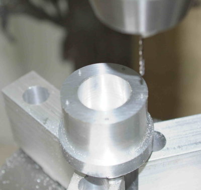
I was inspired by Bogstandard's starting to build this engine, and it looks as if it would be a good (or ambitious) step up from my first two engine builds. For those not familiar with this engine, it's a 5-cylinder radial: http://lineymachine.googlepages.com/l5

Since I still have a bit to finish on the paddleduck engine plus blinging it and Brian's beam engine, I will work on this in fits and starts as time allows. In the meantime, I still need to accumulate tooling that I don't already have.

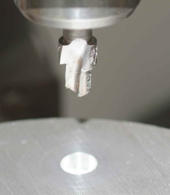
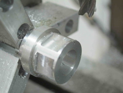
The first bit is a very thin lathe grooving tool to cut the fins on all the cylinders. The plans are showing .025" grooves, which seems almost paper thin to me. I started by grinding the end of a 3/8" HSS blank on grinding wheel, till I had a width of around .07. The remainder of the forming was done on a manual surface grinder at school. The sides need relief, and I guessed at a 5-degree angle on each side (10 degrees included). To achieve this a sine vise was set at 5 degrees using gauge blocks, and the tool clamped in the vise with the botom side of the tool on the high side of the vise jaws. The left side of the tool must be ground first in order to support the tool with a parallel when grinding the other.

I actually ground it down to .03", but decided to stop as the bottom of the blade was so thin. I think that 5 degrees is too much; 2.5 should be better.
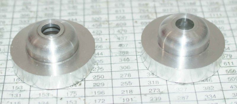
Here's the result:

medium.jpg


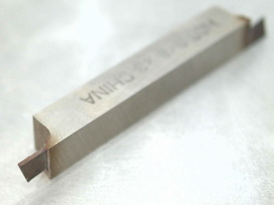
The grooves in the cylinders aren't critical dimensionally, and aren't deep. We'll see how the tool holds up.

Another necessity for this build is a rotary table, and some of the parts will require that it be mounted vertically. I'd been shopping for a rotab for some time, and found the PhaseII 8" H/V on sale at Enco. Unfortunately they don't honor the free shipping on these tables, and shipping would have raised the price by $75. I called MSC, which has a local presence, and was told that they'd match the Enco price. I picked it up yesterday.

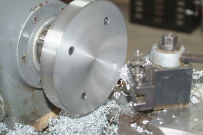
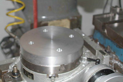
Here's the packing crate, along with a piece of 2" thick 8" diameter aluminum that will be a mounting plate for a 3-jaw chuck eventually. Alongside is a D1-3 backplate that I will use to attach the aluminum to the lathe to cleam up the faces and edges.
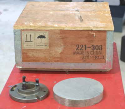
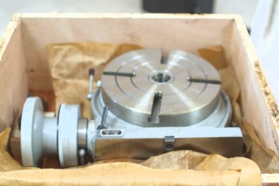
medium.jpg


Inside the crate:

medium.jpg


Once out on the workbench, the only pre-install work to do is to fill it up with spindle oil and clean the table surfaces with mineral spirits to remove the residue from the packing paper. A think coat of oil and it's ready to be mounted.

medium.jpg


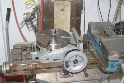
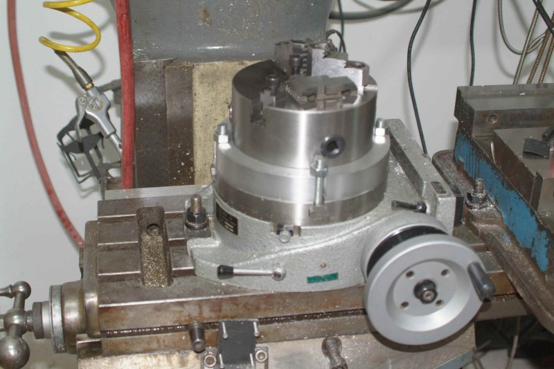
Eventually I will try to separate the vise and rotab a bit, but I didn't want to take the time to retram the vise. There is no vertical slot for the right side. Instead it must be clamped with this supplied bolt/nut/clamp combo:

medium.jpg


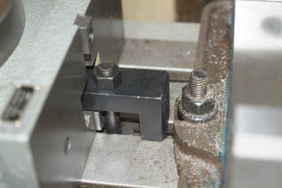
There are two other similar clamps for mounting the table vertically.

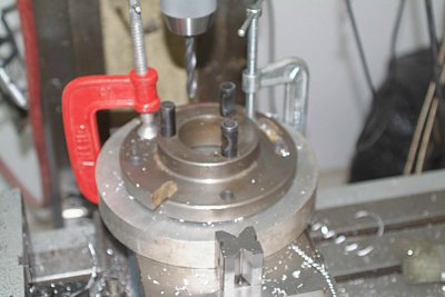
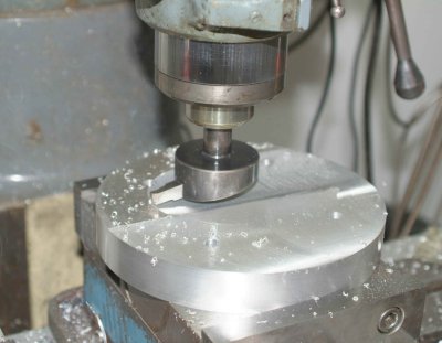
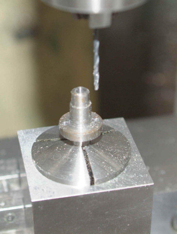
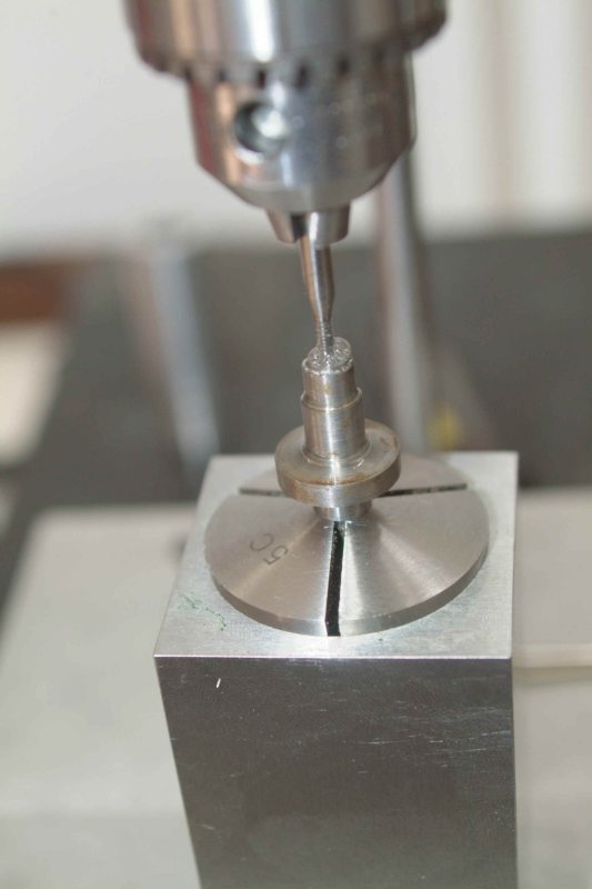
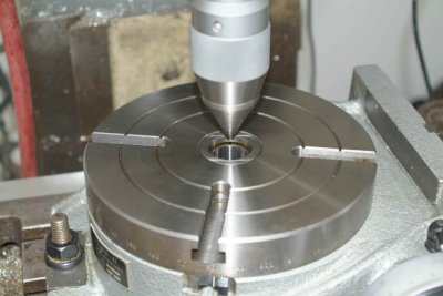
Here's the first method I decided to try to center the table under the mill spindle. I chucked a conic piece of metal that I use as a bull center on the lathe, and positioned the table so that it fit snugly all around when lowered into the center hole. Then I measured with a DTI, which showed that I was less than .005 out of dead center; good enough for me!

medium.jpg
 
wooow kvom, the halo5 that you are going to start is fantastic, surely a step up as you said, but not too ambitious for you, the paddleduck wasn't a joke
however, you have the determination to overcome the difficulties, when they will arrive

and double wooow... the phase II is a good rotary table :bow:, I also wanted to buy one, but it isn't the right moment now
it looks great, and being a 8'' rt, looking how it stays on the table, I think that your mill would not be small: what mill do you have?


BTW, the tool for the fins on your next engine is very well done, stop there, nobody will measure the fins of your halo5 ;)
 
The rotab doesn't come with t-slot nuts, and the slots are smaller than the Bridgeport table slots. I measured the slots and did some internet searching. One eBay seller has the size that fits at a price of $22 for 10. I can't see needing 10, so I decided to make some. The width of the slots at table height indicate the need for 7/16" studs. I happen to have a foot or so of 7/16-14 threaded rod, so I went to the local hardware store to purchase the locking nuts. Once back home, I discovered that my tap&die set has a 7/16-20 NF tap but not the NC. Back to the store to purchase a tap. I then spent a good 90 minutes milling the necessary t-nut form in a 6" length of mystery steel (definitely not 12L14, lots of blue chips ;D), then cut off 4 1" pieces.

After dinner I need to drill and tap them. Hoping not to break the tap.
 
After working on the Jeep all afternoon, I still had a little energy for some machining. I haven't decided which chuck to buy for the rotab, so I started to clea up the aluminum mounting plate. The first order of business was to center the lathe backing plate and drill four holes for the 3/8" mounting bolts:

medium.jpg


Note that since the disc is 8.25" in diameter, I couldn't clamp it normally in the vise. I reversed the hard jaws on the Kurt to allow clamping it for drilling. Once the holes were through, I pulled out this countersink that I'd gotten along with the mill in order for the bolts heads to be below the surface of the plate. Useful gadget.

medium.jpg


Now I could mount it at the lathe to clean up the face and sides.

medium.jpg


Then I flycut the reverse side, hopefully yielding a plate that will keep the enventual chuck square to the rotary table.

medium.jpg


The next step will be to cut 4 mounting notches into the side to attach it to the rotab.

medium.jpg


In the meantime, I will try to start on one part via the CNC lathe at school: the cam housing. The first screenshot show the simulation of the g-code for drilling and boringL

medium.jpg


Assuming that works properly, the piece is turned around in the vise to turn the front profile:

medium.jpg


I'll try them out on Monday afternoon.

 
Looks like you end up with the same predicament I do - first need to make tools to start on a project :D
Nice start on the Halo - looks like a nice one to build!

Regards, Arnold
 
I bought a 6" plain back chuck on eBay last night. It has 2 piece jaws, so even if the runout is too high I can still make soft jaws.

I also found a 8" D1-3 3-jaw chuck with 2-piece jaws on PM. That too will get soft jaws for lathe work.
 
I ran the first half of the cam housing programs on Monday night. Since we have to share the lathe setups, I was limited to using the existing chuck jaws and could add only the boring bar to the tool holder. The existing 3-jaw chuck was set for 2.5" stock, so I needed to adjust the program to turn down from there as opposed to the 2" I had previewed. Since I couldn't drill the stock on the CNC lathe, I needed to cut off 1.5" thick discs of aluminum bar and then drill them 11/32 on the manual lathe.

Using the Haas CNC lathe there is a longish setup process where you touch off the X and Z coordinates for each of the tools your program will use. In this case I was using a turning/facing tool, the boring bar, and the parting tool.

Eventually I was ready to cut, but the first pass is always done by single stepping the program to make sure there are no gross errors that would break a tool or the machine. This took about 15 minutes to make the first piece.

Next I measured the critical dimensions. The boring depth was .008" too shallow as measured by a depth mic; since this is the critical dimension of the part, I needed to adjust an offset for the boring bar to correct for it. The second part was run a bit faster, and then remeasured to confirm the dimension is fixed.

The last two copies were run at full speed, taking 7 minutes machine time for each. One of the pieces received a slight ding, likely by hitting a chuck jaw when parted, so I have two "scrappies" and two good parts.

large.jpg


The second program to form the nose will likely need to wait until next week, as a new set of jaws needs to be bored to chuck the 1.675" diameter. The jawqs on these lathes are hydraulic and have a fairly short range of motion, so they need to be bored to fit a given depth and diameter, similar to soft jaws.

So producing the two good parts has taken approximately 6 hours, including programming, setup, and run time. It's interesting to work on, but obviously inefficient for small quantities.
 
My cheap Chinese 6" plain back chuck arrived today, so I spent the afternoon working to get it mounted on the rotary table. The first order of business was to verify the bolt circle of the 3 mounting holes in the back. I used the DRO to verify that the diameter is 142mm. The holes are threaded M8-1.25, so it was off to the hardweare store to purchase bolts of the correct length. After drilling the holes, I countersunk them with a .5" endmill, but the hole was still a few thou too small. A few minutes with the grinder reduced the heads so that I could attach the chuck to the plate.

With the chuck mounted, there is a 3/4" flange remaining for mounting slots. I milled these with the side flutes of a 1/2" endmill. Here's the result mounted on the rotab:

large.jpg


I removed one of the top jaws for measurement, as I intend to make a set of soft jaws. The next step will be to center the chuck body on the table, and then meaure the runout with the supplied jaws.
 
Kirk,

Might I suggest some washers under those bolts. Hate to see you ruin that nice aluinum plate. I know there's no room on the one side of the bolt. Grind the edge of the washer down so it'll fit.

Bernd
 
Found some washers that fit unmodified. I don't plan to ever remove the chuck from the plate, but the washers do give the advantage that they clear the bolts from the side of the chuck.

I got the rotab chuck dialed in today, although it took longer than it should have. I was holding the DTI in the spindle, but a better idea would have been to use the mag holder on the table. Indicating on the body of the chuck, I got it to within .001". Next I need to clamp a round bar and indicate to see how concentric the jaws might be.
 
I turned the other side of the cam housings on the Hass lathe last night. It turns out one of my "good" ones was bad, so I have 2 good ones left. Hopefully I can drill all of the necessary hole (20 of them) without screwing up on at least one of the two.

large.jpg


Since I have machine time this week, I'm going to CNC the driveshaft as well. I cut off 4 2.25" pieces of 3/4" 12L14 before leaving. I'll face off at home, and turn them on Thursday if all goes well.
 
I turned the driveshaft on the Haas lathe at school last night. I started with 4 blanks and managed to get only one good part. Since I won't have access to the machine anytime in the near future, this is the last part for this engine I'll be able to make via CNC. However, at least I was able to run the two parts that have the critical dimensions.

large.jpg


I still need to drill and tap 3 holes on the part. I bought a package of 2-56 taps on eBay yesterday, so hopefully I won't fubar this.
 
I have been working on the crankcase over the past few nights as time permitted. I'm sure John will make this a lot differently as he has 6 to do, but here's my effort.

Since I had a precision 1" bore in the rotab chuck's soft jaws, I chucked a piece of 2" dia. aluminum rod in the lathe and turned down one end to 1" diameter. On the other end I turned down 1" in length to the required diameter of 1.65". I then bored the interior to .75" for a depth of 1". I don't have a good boring setup for the lathe as yet, so further boring will be done on the mill.

Having previously dialed the rotab in to work on the cam housing, I was able to chuck the raw crankcase without further ado. I then used an endmill to enlarge the bore to just over 1".

medium.jpg


Since all of the holes to be drilled and tapped into the interior will cause burrs, I plan to bore to the final diameter of 1.25" after all the drilling is done. This will remove the burrs, which might be difficult to access otherwise.

Next the mounting holes for the cam housing were drilled.

medium.jpg


With the crankcase still in the chuck, I tilted the rotab to the vertical position. Here's my method of squaring it to the mill table:

medium.jpg


The mounts for the cylinders were machined next. I used a .75" endmill that was actually only .725", so each flat needed two extra passes to attain the necessary width.

medium.jpg


I spot drilled the five holes needed in each flat, then drilled and reamed the center hole to .500".

medium.jpg


Next there were 20 mounting holes to be drilled with a #50 drill. I have two of them, but somehow I have lost or misplaced one of them. Since there are a lot of holes this size to be drilled I hope I find the spare.

medium.jpg


Given the angles of the mounting holes, I just tapped them 2-56 using the guide I had previously made to tap on the mill or lathe. It turned out to be very easy to tap aluminum with this setup. The weight of the chuck was enough to start the tap cutting, and the taps cut very well. Less than minute for each hole.

medium.jpg


Trial fit of some screws:

medium.jpg


Unchucked the crankcase and put it on the tapping stand to tap the 5 holes for mounting the cam housing.

medium.jpg


The next step will be to bore the interior to final dimension. I will hold off parting off the crankcase as long as possible.
 
Looking good, Kvom!

Please keep up with posting your progress, this one is on my "want to build" list, so a tutorial will come in VERY handy ::)

Cheers, Joe
 
kvom,

Lovely job on the crankcase. :bow: :bow:

Best Regards
Bob
 
a very well done work on that crankase kvom :bow:

I'm happy that your tapping stand works well too

keep up on this great built
 
Here's the finishing touches on the crankshaft. I drilled the center hole on the lathe, and then mounted in the collet block to drill the two holes in the flange (these holes are used to attach the cams).

large.jpg


Then all three holes are tapped 2-56 at the tapping stand. Once again, the weight of the tap and chuck were enough to start the tap easily in the steel (12L14).

large.jpg
 
Back
Top