Liney Halo

Home Model Engine Machinist Forum

Help Support Home Model Engine Machinist Forum:

This site may earn a commission from merchant affiliate links, including eBay, Amazon, and others.
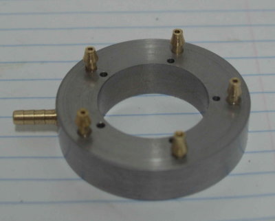
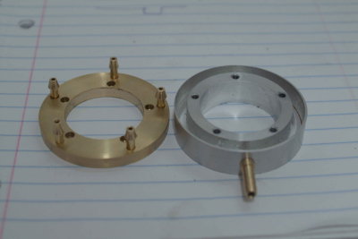
I decided to make the hose barbs myself using some .25" brass round. Nothing too complicated other than some tedious tool changes on the lathe. Outer barb diameter is 3/16", with the inner diameter 1/8" and the air passage 1/16". I then drilled the mounting holes in the manifold cover, reamed oversize, and fixed the barbs with red loctite. The inlet barb I just cut from a store-bought connector and loctited to the body of the manifold.

medium.jpg


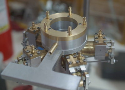
With the loctite cured overnight, I assembled to the mount and crankcase.

medium.jpg


Then it was time to connect some platic tubing.

medium.jpg


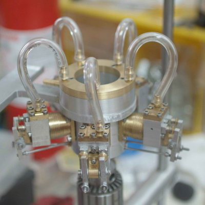
I gave the moving parts a dose of oil and hooked up the air. Unfortunately things went less well from there. It turns out that the inside seal between the manifold cover and body isn't airtight, and all the air is exiting there rather than going to the cylinders. So my plan is to make a gasket from oiled kraft paper, as shown on a recent thread.

As I was disassembling the manifold from the engine, I noticed that it wasn't screwed tight. So now it seems that the mounting screws are several threads too long, meaning that the cover was not cinched down tightly to the body. Rather than cut the screws down, I'm still going to make the gasket first.

While everything was assembled, I did a few minutes run-in with the electric drill, and the mechanism doses seem to be turning with less force. I may attach it to the mill spindle and let it turn at low speed for a longer period while the gasket making gets underway.
 
That's a dirty trick, Kvom! I scrolled down, then a little more, then all the way. No movin' picture!

I'm glad you got it going, and I'm staying up 'til 11 waiting to see.
It's quite a build. Heck, each jug and head is a build on it's own!

Tapping my foot.

Dean
 
[ame]http://www.youtube.com/watch?v=0ia59lEwFEQ[/ame]​


After the early afternoon trial, I made a paper gasket and oiled it to try to seal the manifold. I still needed to shorten the screws to get everything tight. I also hooked the shaft to the mill and ran it for about 30 minutes at ~300 rpm. At the end, the mechanism was slightly less tight.

I then needed to readjust the timing. The connection of the crank to the shaft is by a single flat-head screw. If the engine is turned the wrong way, the screw will loosen and the crank will not be turning. So it is important that the engine only turn clockwise as viewed from the front.

I also adjusted the timing so that the piston is slightly past TDC when the inlet valve opens.

Once all this was done I reattached the air and started to turn the engine by hand via the attached chuck. I started to feel a bit of a kick, and then it sprang to life. The manifold is still leaky, but not as badly as before so that the cylinders are getting air. I imagine that with a better sealed air supply it should run at lower supply pressure.
 
Great!! And I didn't even have to stay up late to see it. Thanks for the vid, and congratulations!

I know you'll get it smoothed out. You've got the hard part knocked.

Dean
 
Congratulations kvom.
Thanks for the vid.
It's wonderful.

Yeah when I saw the other post I was thinking, 'dirty rotten scoundrel tricky thing to do' ;D but I kept checking in...glad I did!
 
Runs pretty damn good for having, "a little friction in the system".

Congratulations kvom on a magnificently documented build! :bow: :bow: :bow:

Rick
 
kvom,

Great stuff. Your persistence has sure paid dividends. :bow:

Congratulations for a fine engine. :bow:

Best Regards
Bob
 
congrats kvom, great running engine, great looking one too, and a very well documented build :bow: :bow: :bow:

you may be very proud of it! 5 cylinders (so 5 pistons, 10 valves, etc.), lot of work and everything that must run in synchronism... well done :bow:


Congrats. Nice runner. Persistence pays huge dividends. I never had any doubts. ::)

Ron
 
Thanks to everyone for following along. Credit is due to John "Bogstandard" for first pointing me towards this engine and also for demonstrating how to cut very thin fins in the cylinders.

I still need to make a suitable base as well as fix up the manifold. I'm thinking I may try some RTV in place of the gasket. Or I may try a different design.

Then I'll need to study up on polishing and bling, as this and my previous builds all need some.

For anyone considering this build, I can recommend it as a "step up" for those like myself who have done a couple of builds. My thoughts are:

1) The tolerances are not particularly tight, except in a couple of places.

2) I was initially intimidated by the use of 2-56 screws for all the fasteners, but in reality they pose no problems whatsover. I didn't break any drills (50 and 43 for the holes) nor a tap. Use of a tapping stand or equivalent is a definite requirement. Since I have a DRO on my mill, lining up the clearance holes to the tapped holes was straightforward. That said, there is no reason that the clearance holes couldn't be drilled somewhat larger to make fitting easier.

3) A rotary table is a requirement for this build, and was the major tooling expense I had. I made soft jaws for the rotab chuck, and these made precise positioning on the rotab much easier and faster.

4) Other tools I bought to make the build easer were a set of O/U reamers and the 2-56 HSS taps. Buying the fasterners and bearings from Liney along with the plans was also a good idea, as there were 5 different lengths of screws, the two bearings, hose barbs, wrist pins, and all the little balls. While everything could be sourced elsewhere, having everything delivered in one package was very convenient. I did buy a box of 2-56 x 1" SHCS as extras.

5) Materials are pretty flexible. While I used brass for the cylinders for looks it's not really a necessity. Aluminum can be substituted for brass in the cylinders and heads. In any case, I bought the brass rod needed for the cylinders on eBay for less than $15, of which I used only about a quarter.

6) While I used a CNC lathe to make the cam housing, it wasn't necessary to do so. Turning the rounded profile on the nose was easy with CNC, but could also be done manually with a bit more effort. The actual shape of the nose profile isn't critical in any case.

7) To cut the very thin fins on the cylinders I needed a surface grinder to make the grooving tool. The fins are of course decorative and a normal cutoff tool could be used for wider fins (or no fins at all).

And finally, it should be possible to make this engine with fewer cylinders given suitable modifications to some measurements.
 
Congrats! I really like the way these things sound. :bow:
 
Congratulations on a very nice build. Thanks for the journey.
Gail in NM
 
Kvom

Congrats and thanks from me too! I've enjoyed following along.

Joe
 
Sweet! Thanks for the notes and observations as well. It can be tough to look at a finished model like that and know if it's within your capabilities.
 
Nice job, KVOM. Gotta build me a radial one of these days.
 
Very nice job on getting your engine running.

Excellent craftsmanship.
 
I spent the afternoon rethinking and then remaking the manifold. Here's the result:

medium.jpg


The body, made of 12L14 steel is actually two pieces. The first piece I turned as a disk 2.000" in diameter, .5" thick, and bored out to 1.250". I then used a grooving/cutoff tool to turn a groove into the outside .25" wide and .35" deep to provide the air channel. The second piece I turned 2.25" in diameter and bored .199. I then pressed piece one into the bore of piece two. Then it was off to the rotab to drill the mounting holes and holes for the air barbs.

I mounted it to the engine, and while it's not 100% airtight at the pressed seam, it's a lot better then before.

Unfortunately, the engine then decided not to cooperate by running at any pressure. Seems the crank screw had loosened up again. Arghh!

So next shop session I'll adjust the timing again and tighten the screw. I also want to check all the valve again as I didn't seem to feel proper airflow from every exhaust port.
 
Ref to the leak. Can you soft solder if at the seam?
 
Back
Top