Liney Halo

Home Model Engine Machinist Forum

Help Support Home Model Engine Machinist Forum:

This site may earn a commission from merchant affiliate links, including eBay, Amazon, and others.
Thanks, My plans do not even mention balls are used. I have redrawn the engine in autocad
 
There are two sizes of balls used. The 3/16" for the valves, and 1/8" balls for the rod lifters. These small balls ride on the cam surfaces; the rod plungers sit on top of these; the pushrods connect the plungers to the rocker arms.

Rather than any assembly drawings, Liney provides a set of transparent sheets with various assemblies drawn to scale. By putting these on top of each other you get an idea of how the parts interact.

Today I spent a couple of hours in the shop. The first order of business was to make a new "flywheel", as the one I made from the end of an axle shaft was too hard to tap for a set screw. I made the one in the photo from a scrap piece of hex 12L14 steel. I drilled the cross hole 1/8", then counterbored with a #7 drill and tapped for the 1/4-20 screw. There are 3 #4 lead shot between the engine shaft and the set screw.

medium.jpg


After finishing seating the valves in the last head, I worked a bit on the pushrods. These are simply 1.4" lengths of 1/16" drill rod. I cut them a bit long with a wire cutter, then filed both ends flat and to length. However, my first fitting showed them to be a bit short. So now it seems that either I need to have longer rods, or else the valve plungers need to extend higher from the heads. The latter means that the springs may need to be longer.

From the plans, the cams have a radius difference of only .05" between the open and closed valve positions. This means that the plungers will only move .05" to open the valves. Somy next shop session goal will be to determine where then plungers need to be in the closed position, and adjust to suit.
 
Did a couple of small tasks on the engine:

First I remade the crank pin a bit longer so that I could tighten the screw without binding the piston rods. There is really no reason that it can't be longer than the plan's dimension.

I "discovered" that I had failed to machine the pocket in the head that I was test fitting the pushrods on. That meant that the rocker and its arms were .05" too high. Hopefully the next time I put it together things will fit better.

As far as I can tell, I have everything set to try a test run the next time I get into the shop.
 
Zee, Kvom....
We've all been cheering both of you on and watching all your hard work as it has come together. With both of your engines nearing completion, you two are just about to create the perfect storm for the POM voters....LOL

Steve

Steve
 
Cedge said:
Zee, Kvom....
We've all been cheering both of you on and watching all your hard work as it has come together. With both of your engines nearing completion, you two are just about to create the perfect storm for the POM voters....LOL
Steve

No kidding!!

Dean
 
Now stop that! I'm hardly in kvom's league.
But I'll be happy to be a nominee and make his win easier. ;D
Please return to the original broadcast. ;D

Much appreciated.
 
Thanks for everyone's support. But to be realistic, even if it turns over on the "test stand" I will still need to make a suitable base plus a manifold to replace the 5-armed monstrosity I cobbled together. I have some ideas on this, but nothing solid yet.
 
I did the recommended tuning and adjustments as recommended by Liney for the first cylinder, and after some fiddling got a runner. Here's the evidence:

[ame]http://www.youtube.com/watch?v=IvhgMdTBUYM[/ame]​

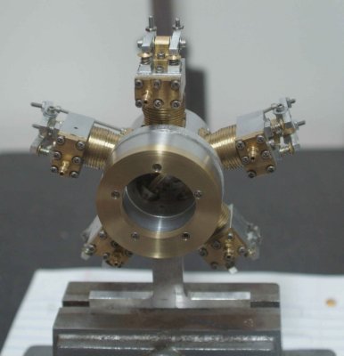
To get enough flywheel weight I clamped my tapping station chuck onto the shaft. On the video, I started it at 40 PSI and gradually reduced the pressure to 20 PSI at which point it stops. With more cylinders and some run-in I expect it will run at a fairly low pressure. For other builders I will reiterate the setup process and some issues I encountered.

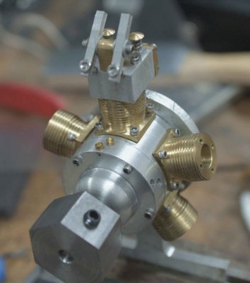
My first "concern" was realizing that the pushrod holes in the cam housing are not centered on the cylinder. It seems that my setup on the rotab was a bit off. While the drawings from Liney show the pushrod for the inlet valve connected to the rear hole, I decided to reverse this to make the rods more upright. Since the cams are symmetric, this isn't a problem as long as all cylinders are set the same.

The first adjustment is to set the crank pin/conrods relative to the cams. This is the sole timing adjustment and is needed only for the first cylinder. I slightly loosened the screw that holds the crank to the shaft and then turned the shaft until I felt the inlet cam contact the ball bearing that pushes the inlet rod. Holding the shaft steady, I pushed on the crankpin so that the piston was at TDC (i.e., you want the inlet valve to start to open at TDC). Now it's time to tighten the crank to the shaft; however, the conrod blocks access to the screw head, so I needed to slowly rotate the shaft and crankpin together until I could get to the screw with a small screwdriver. It's for this reason that you need some friction with the screw initially: loose enough to be able to adjust the crank pin but tight enough so that the pin turns with the shaft. Note that I set it up so that the engine turns CCW as seen from the front; to reverse this direction turn the crank pin 180 degrees relative to the cam.

Next, the travel of the rocker arms needs to be adjusted. Connect air at low pressure and turn the shaft until the inlet valve is open. Then adjust the outlet rocker via the SHCS until air is coming out of the exhaust. Next back it off until no air is exhausting. The exhaust pushrod length is now set. Now you can lock the adjustment screw with a 2-56 jam nut. The small issue I had with this is that the screws supplied may not be long enough to protrude out the top of the rocker. For this reason, I plan to use longer screws on the other cylinders and cut off any excess once the jam nuts are in place. A 3/16" nut driver is an excellent tool for tightening these small nuts.

The same procedure is followed for the other pushrod. Turn the crank so that the exhaust is open and adjust the inlet pushrod until air enters the inlet valve; then back off and lock the jam nut.
 
Sweet, it runs.. only 4 more cylinders to go, right?
 
Fantastic! I bet that felt superb!
When you got it going an 'oh!' popped out of me.
Congratulations.
 
That one cylinder has a lot of work to do all by its lonesome. Once you get its pals bolted up, I'll bet it runs down nice and slow, and on a lot less pressure.

Good going, Kvom. Will be great to see it all up and swinging a prop!

Dean
 
Last night I started to assemble the other cylinders. With two installed the engine wouldn't run, although each would kick the piston. I suspect that the additional resistance of the springs plus the cams against the followers stalls it out.

So I just added each cylinders, adjusting the valves as described above. When I got to the last one I discovered that one of the rocker arms was sitting cockeyed; looks like it wasn't chucked properly when drilling the cross hole. Luckily I had made one extra arm, which needs only to be drilled & tapped. So once I can do that I can try a 5-cylinder run.
 
My first 5-cylinder trial was not a success. ???

First I had to remake the skewed rocker arm, and the blank I had left over from the first batch was too thin. So I spent probably an hour making one from a bit of 1/4" thick aluminum. Note to self: finally buy a set of thin parallels.

Once assembled, the last head seemed pretty leaky on the output valve, but I decided to hook it up anyway. Applied air up to 60 PSI without a runner. Then I noticed that the crank had become loosened from the shaft so that it wasn't turning. By then it was to late to pursue a readjustment.

With all cylinders attached, there is a fair amount of force needed to turn the shaft by hand. Lifting the pushrod to open a valve has a hole train of friction and resistance to overcome, and since there is only one piston delivering a power stroke at the point of contact it needs to have enough power to overcome the resistance. A heavier flywheel would help as well.
 
First trial was a success.

A trial is unsuccessful when nothing is learned.

We all know you'll get there.
 
zeeprogrammer said:
First trial was a success.
A trial is unsuccessful when nothing is learned.
Now, THERE'S a cool quote. ;D

Keep at it, man, and keep us updated. You'll get it, and I wanna see it.
 
zee, I like that! Mind if I steal it?

kvom, I know you'll get it figured out. It's always the basics, one step at a time.
 
Wow, that sounds great, even with only one cylinder. Can't wait to hear the finished engine.
 
Rather than work on getting the engine to run, I decided to start building the manifold, which will be a lot more practical than the temporary "octopus" I cobbled together. So getting back into the shop after a few days away visiting relatives, I fabricated the two pieces shown to the right of the engine mount I made earlier:

medium.jpg


The center part has the circular air canal, and the brass part on the right is the cover. All three pieces bolt together and attach to the crankcase as shown here:

medium.jpg


To make it operational, I need to make/find 5 small hose barbs that will attach to new holes in the brass cover, as well air inlet barb.

FWIW, the aluminum part is .5" thick, and the brass cover is .2" thick. The air channel is 3/16" wide and .35" deep.
 
Back
Top