Liney Halo

Home Model Engine Machinist Forum

Help Support Home Model Engine Machinist Forum:

This site may earn a commission from merchant affiliate links, including eBay, Amazon, and others.
Kvom---I haven't said anything before now on this thread, but I want you to know how impressed I am with your work. You are going places with this build that I am quite sure are beyond my capabilities. Best of luck, and yes, I watch your builds as well.----Brian
 
Made the cams:

large.jpg


I turned some brass rod down to .780" and drilled the center hole, then mounted it in the rotary table to mill the rest of the profile and drill the mounting holes. Then it was back to the lathe to part off two "slices". Finally I milled the cams to the desired thickness.

Here they are mounted on the driveshaft:

medium.jpg


The dimensions given result in a very precise, tight fit. To get the screws to line up with the taped holes in the shaft I needed to file the center hole slightly to give some wiggle room. I also think a #43 drill for the mounting holes would be preferable to the #44.

One issue to resolve at assembly time is the angle the crank pin needs relative to the cam lobes. The cam nearest the end drives the input valve, so I'm guessing that the valve should start to open somewhat just before TDC. Comments?
 
I'm enjoying watching your progress on this, Kvom. Sorry to hear you have to remake the heads!
This is an impressive looking engine when finished, and I was pretty smitten with it the first time I heard it run in a video. It sure sounded good, to go along with it's good looks. I'm rooting for your success!

The prints look pretty good from what I see in your pictures here, but seem to use unconventional dimensioning.
In your picture of the cams, what does the call-out of 11 degrees refer to? The end of the .680" dia? It almost looks like it's referencing the outer dia of the #44 hole. Just curious about that.

Thanks for the write up here.

Dean

 
I think the 11-degree is an error. Since the flats are milled at 10 degrees from the centerline, 11 ought to be 10 as well. In any case it's unnecessary.

WRT dimensioning, Liney states that some dimensions are left off to keep the drawings uncluttered. Sometimes you need to look at the drawings for another part to find a dimension. So far I haven't had any difficulties in that respect.
 
kvom said:
WRT dimensioning, Liney states that some dimensions are left off to keep the drawings uncluttered. Sometimes you need to look at the drawings for another part to find a dimension. So far I haven't had any difficulties in that respect.

I was thinking about his use of extension lines and the practice of using "dia" in place of "R" for incomplete circle lines. I don't mean to imply there's anything wrong with the prints. Was just something I noticed.
Thanks,

Dean
 
After a weekend spent mostly watching the Presidents Cup golf matches on TV and some assorted honey-dos, I spent the afternoon in the shop making a little progress.

The first order of business was to get the bearing retainer finished. Since I now had a 3/8 under reamer, I mounted the piece in the lathe and reamed the center hole to .374. Then I parted off the part and spend some time cleaning up the mounting holes; the tapping stand was useful for this. Then there was the obligatory trial fit:

medium.jpg


Looks as if I need a deeper countersink for the screws, and some filing to make the spokes a bit nicer. I did a quick test of the bearing supplied by Liney, and it looks as if it will be a nice fit - not loose but not terribly tight either.

Not being overly ambitious, I decided to just make the rocker pins. Although these are pretty darn simple, they were tedious to make with lots of ins and outs on the collet chuck. First, hacksaw off 5 pieces of 1/8" brass rod a bit longer than the finish length; next face all 10 ends to get accurate length measurement. Then face off to final length. Now I needed to center drill each end, as I was not sure that I would get a straight hole drilling through from one end. So I drilled halfway, then turned around and drilled through from the other side. The final operation was threading each end, using the bushing I made to fit the tapping chuck. So I probably spent two hours just to make these 5 small, simple parts.

large.jpg
 
Sometimes small "simple" parts seem to take the most time, but it's pretty neat when you make a bunch up and they all fit! Enjoying your build.

Dean
 
More shop time making little fiddly parts the past few days.

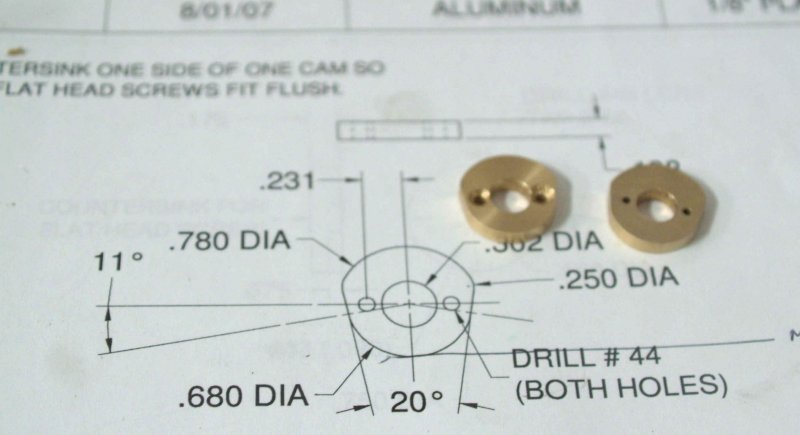
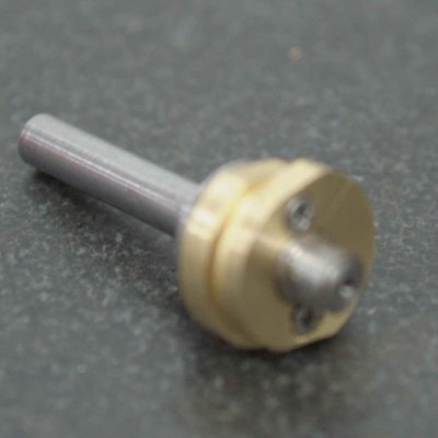
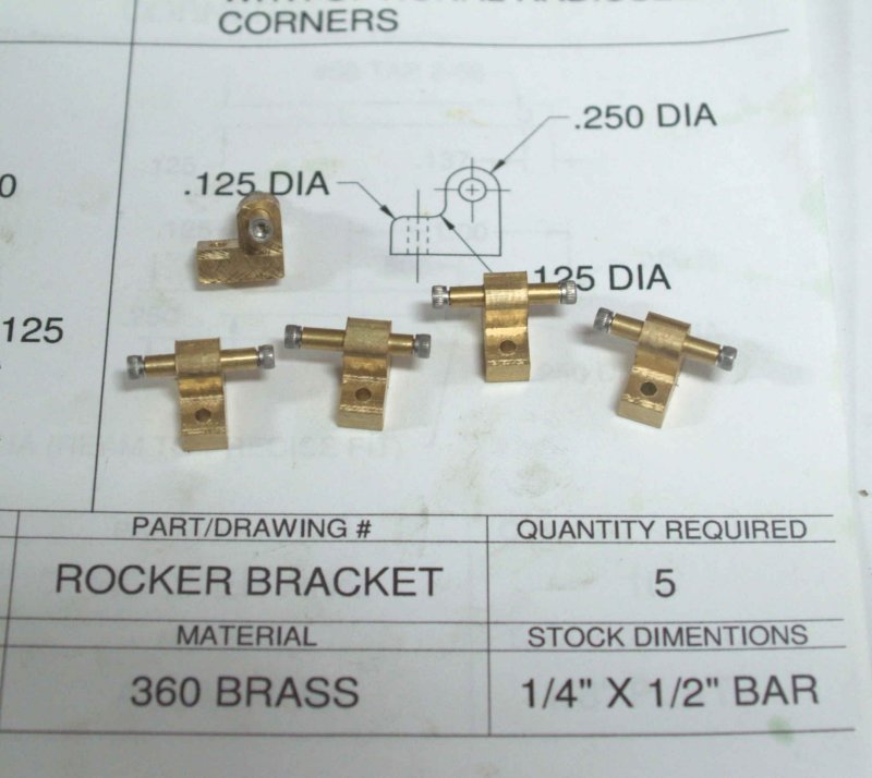
Since I obtained my O/U reamers, I reamed the cross hole of the rocker bracket and inserted the rocker pins. Not a press fit, but I suppose brass rod isn't necessarily on size.

large.jpg


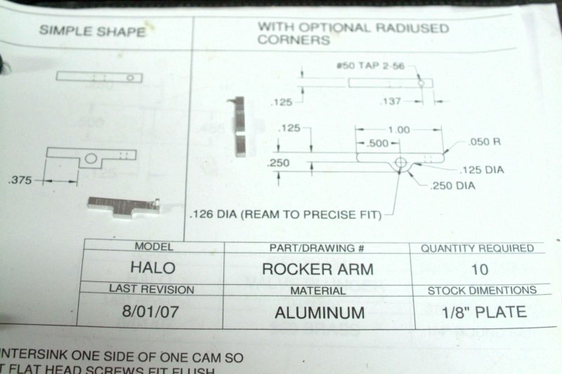
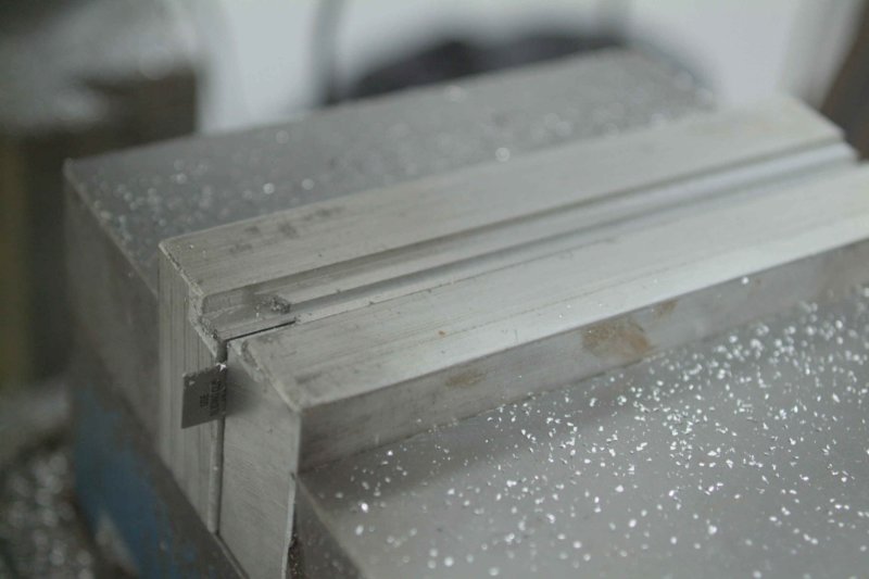
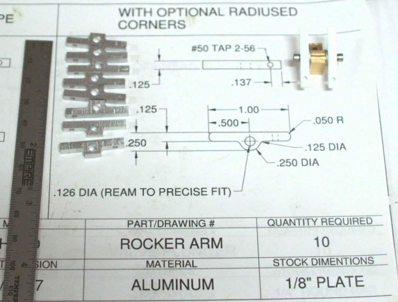
Next I started on the rocker arms. I first took a 6x6" piece of 1/4" aluminum plate and cut off as slice that I machined to 1" wide. I then milled the profile of the arms. The sides of the center section were milled with a 1/8" ballend endmill to obtain the rounded corner profile. I then used a 1/4" endmill to slice off 10 pieces. At the end of the cut the pieces would snap off leaving a large burr that would need to be milled off later.

large.jpg


The next machining steps required the use of soft jaws on my Kurt vise, as both the rockers and the connecting rods to follow are 1/8" thick. After mounting the jaws, I milled off the existing slot with a 1/8" endmill to get a flat starting point. Then I clamped a 6" rule between the jaws to allow clamping room later, located the center of the slot with the edge finder, and milled a 3/32" deep slot with a 1/8" endmill.

large.jpg


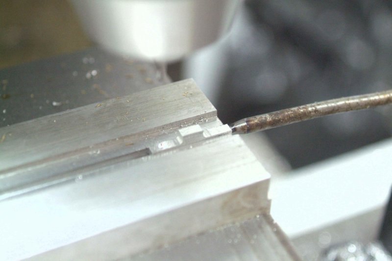
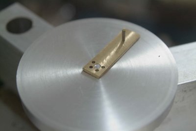
After positioning a vise stop and locating the x-axis with the edge finder, I was able to mill off the burr from each piece, and then drill the vertical hole that will accept the pushrod:

large.jpg


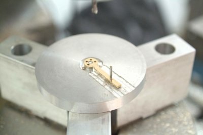
The same setup was used to spot drill, drill, and ream the cross hole for the rocker pin.

large.jpg


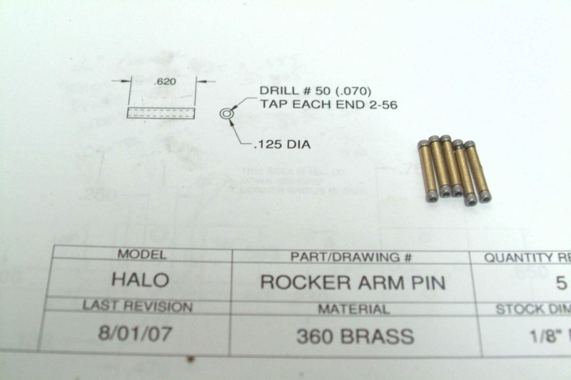
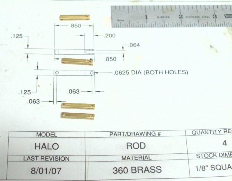
Finally, I cut four pieces of 1/8" square brass rod (using a wire cutter is quicker than hacksawing), and used the same vise slots to mill to length, drill the cross holes, and finally mill the slot in the end (1/16" endmill):

large.jpg


For those who haven't tried soft jaws and have a vise with removable hard jaws, I can recommend them for holding thin pieces where parallels are impractical. Note that you can drill into the jaws through the pieces, which is not a good idea with hard jaws.
 
I see that you do manage these serial pieces in a neat way

very efficient and very well done!

 
Yesterday and today I worked on the most challenging part thus far, the master rod. Because of the irregular shape I figured I needed a jig to hold it. First I reduced a small piece of 1/4" brass to .375" wide by 1.25" long and drilled the holes needed for the wrist and crank pins. After reaming the crank pin hole, I machined it to 1/16" thickness.

For the jig, I found a 3" diameter disc of aluminum about 3/4" thick. I turned one side for a 1" diameter spigot that would mount on the rotab, and then turned the other side with a small .125" spigot that would be a tight fit for the crank pin hole. Once mounted on the rotab and centered under the spindle, I set the rotab to 0 degrees and drilled a .063" hole .850" from the center. I then could mount the workpiece on the center spigot and hold it laterally with a piece of 1/16" drill rod. I then drilled the 4 holes to which the other connecting rods will be pinned:

medium.jpg


Next using a 1/8" endmill I tried to carefully machine the profile using a combination of linear and rotary motions. Unfortunately it seems I had a slight undercut on one side.

medium.jpg


I trimmed the tail to length leaving a workable, although less than perfect, master rod.

medium.jpg


Some lessons I learned. I had intended to drill and tap a hole in the tail as a hold-down (for that reason it was left long). When I first mounted it on the jig it was very solid, so I neglected that step. On a do-over I would do so as the piece did have a tendancy to lift when milling the tail portion. Rather than the spigot in the center of the jig, I would just drill a hole and insert some 1/8" drill rod.

 
Nice kvom. I'm going through a similar process on my reversing lever. It is very much a learning experience.
 
Since my house was invaded this afternoon by 7-8 teenagers at the invitation of my daughters, I decided to hide out in the shop. It was finally time to turn the fins in the cylinders, as they had been waiting since 9/28 to be finished up. Bogstandard has a fine writeup on setting up the very thin parting tool (.025", no relief), and I followed it pretty much as written. Since the tool needed a surface grinder to create, others attempting this build might choose to use a wider, commercial tool and cut fewer fins (or no fins at all). I was able to chuck the parts in my Jacobs Rubberflex collet chuck, and the cuts were surprisingly easy.

Like Bogs I had written down a list of X-Y coords for each cut, and it took only about an hour or so for all 5. Having a DRO on the lathe makes this a much easier proposition. Then I reversed them in the chuck to cut down the bottom spigot to length. One thing I did differently was using a 1/16" parting tool to turn down the three bottom fins; this avoided the thin wires that would result from using the thinner tool.

large.jpg


My list of to-do parts is getting smaller. I still need to drill the many, many holes in the heads and make the 5 pistons, and then I can think about some assembly, a base for mounting, and some sort of air manifold.
 
Gday all. Just ordered the Halo plans and castings from Liney. The thread and video sold me. I am also building the PM lathe which I plan to power by the Halo on steam. I will post when I start it. Geoff. PS, I live in PENGUIN, Tasmania.
 
That combination should be really interesting!

FWIW, the kit doesn't have castings, just bar stock and fasteners. I ordered just the fasteners and used my own metal.
 
I had a little more shop time before leaving for the long weekend, so I "caught up" on some tapping. This model needs a lot of tapped holes. Each of the 5 cylinders and their attached parts total 20 2-56 holes. Without the tapping stand I made a short while ago this would have been mission impossible. ;D
 
Man.. That's a lotta little holes to tap. I had about 10 little bittys to do today and that was enough at one time. 100 tapped holes at a whack is real dedication!

Enjoying your build.

Dean
 
Now to put the cat amongst the pidgeons. Correct me if I'm wrong, but with the cam proflie being what it is, it looks to be an easy job to add another 4 cylinders and turn it into a 9. If you are making 5 cyclinders , not much extra time for another 4. Once I start will make a 5 and a 9. Geoff
 

Latest posts

Back
Top