Liney Halo

Home Model Engine Machinist Forum

Help Support Home Model Engine Machinist Forum:

This site may earn a commission from merchant affiliate links, including eBay, Amazon, and others.
I recently bought some 1-1/4" brass round via eBay for the cylinders, and since they arrived I decided to make the first one to see if my imagined machining sequence would work. It's a bit different from John's, but doesn't require any jigs.

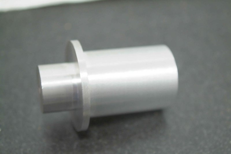
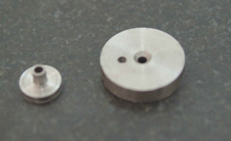
The first step is to turn the basic shape. First turn the 3/4" upper section, then drill and ream the bore, and part off at 1" of length. I then reversed the piece in the chuck and faced the cut end. After measuring, I rechucked on the 3/4" section and turned the bottom to 1/2" diameter leaving .100" for the flange. That completes the lathe work for now.

large.jpg


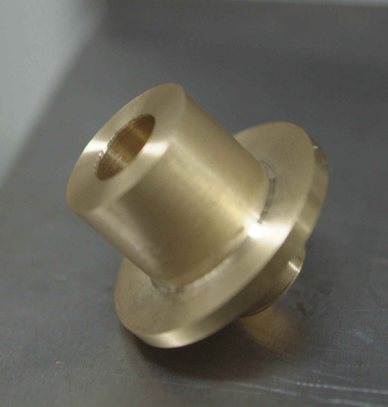
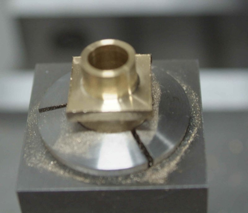
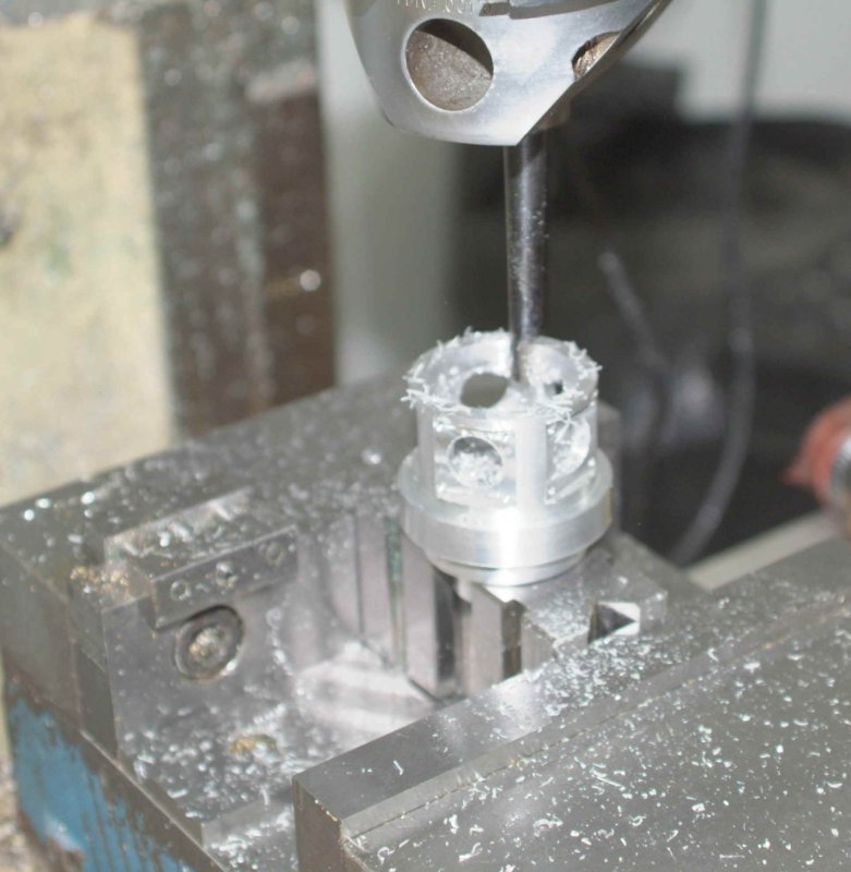
I chucked the 3/4" end in a 5C collet block, mounted the block horizontally in the mill vise, and milled the flange to 3/4" square.

large.jpg


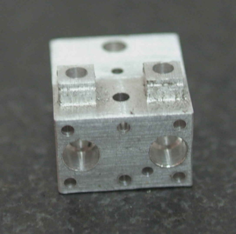
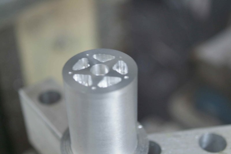
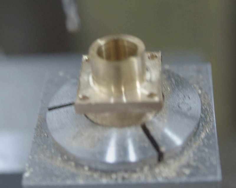
Next I mounted collet block vertically, located the center, and drilled the 4 mounting holes in the corners.

large.jpg


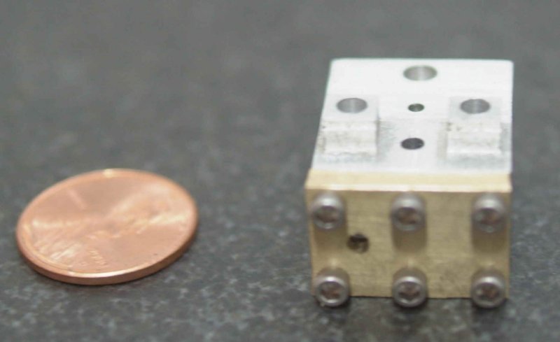
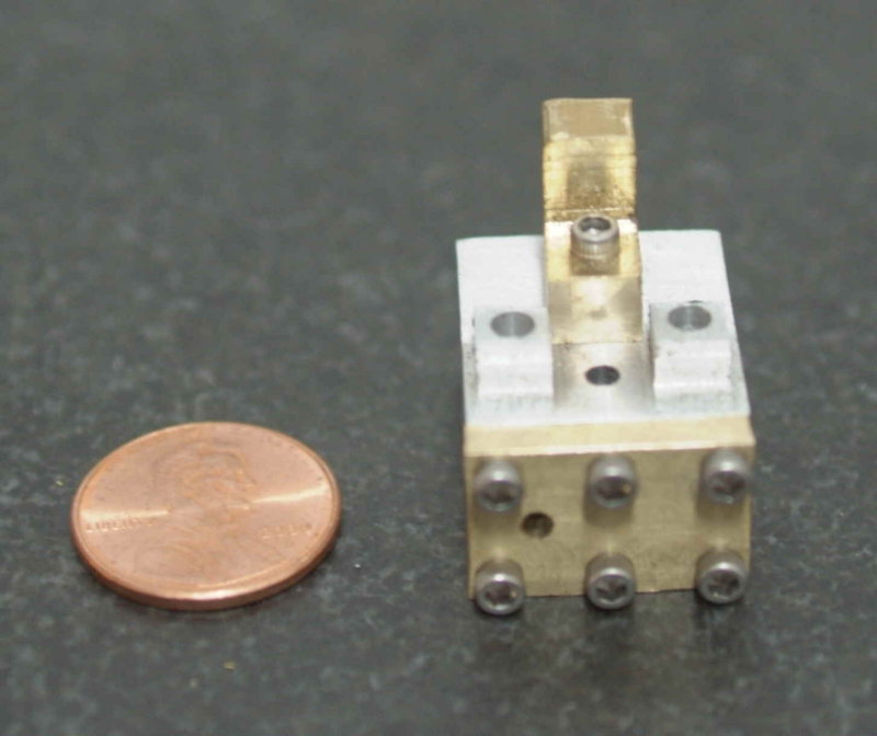
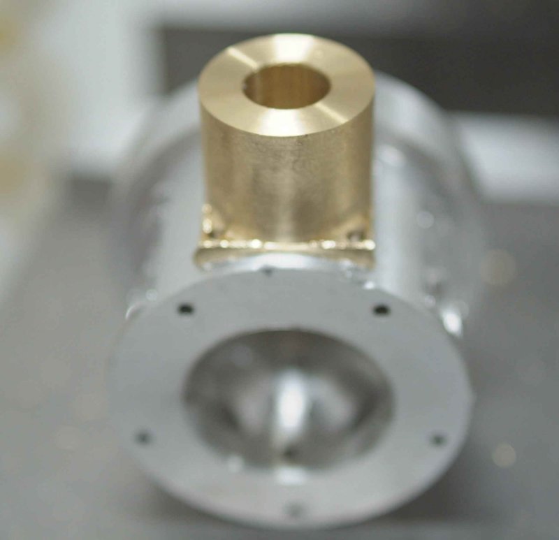
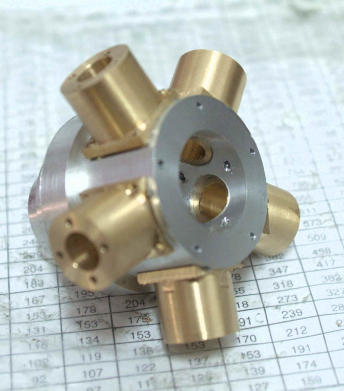
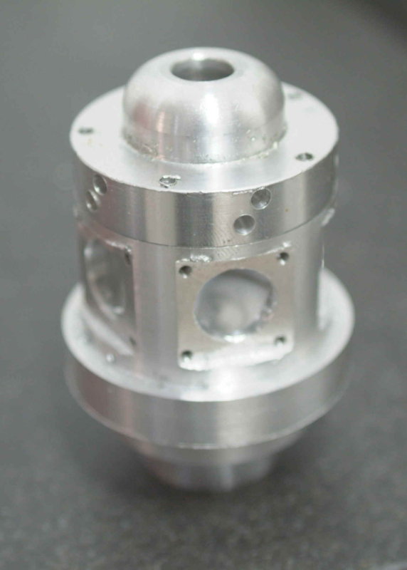
A quick test fit onto the crankcase:

large.jpg


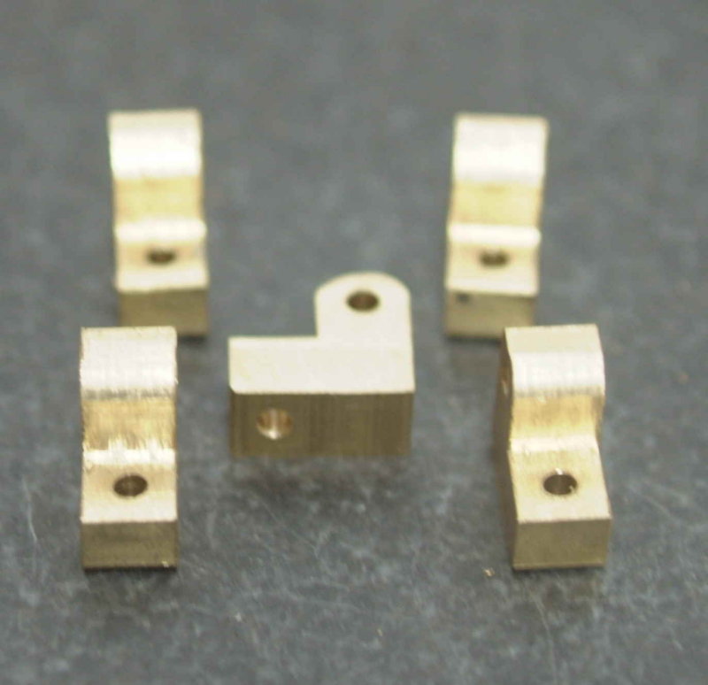
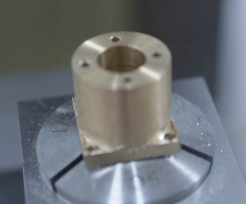
Finally I reversed the piece in the collet block using a 1/2" collet, squared the flanges to the block using my height gauge, and drilled the mounting holes for the head.

large.jpg


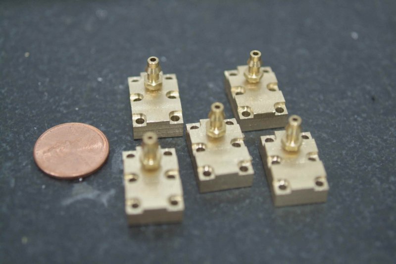
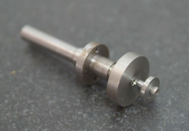
Given that I have too many balls in the air project-wise, I probably won't make the other 4 anytime soon. In any case, I still need to tap the holes on the top, and cut the fins. I will definitely be following John's process for setting up the parting tool in the lathe for that. Once the fins are cut, the only remaining worj will be to shorten the 1/2" spigot to .100"; it's made ~2.5" initially to give more surface for chucking in the collet and lathe.
 
Today I finished roughing out the other 4 cylinders. They all need the same finishing: tap the holes where the head mounts, cut the fins, and trim the bottom spigots to length. In the meantime, a poser shot to test fit on the crankcase:

large.jpg
 
Kvom
You're looking darned good so far. I'm quietly watching your progress and planning for the time when I take on one of these little engines, so keep it going!!

Steve
 
Looking pretty real kvom.
You've got two very nice projects going (i.e. the Paddleducks too).
 
Kirk,

I seem to remember about 12 months or so back you were just gonna just "lurk" till you had a bit more experience, well ....... your lurking days are certainly over ................. excellent work mate :bow:

Very well done ;D

CC
 
Made a few more parts fpr the engine. First up was the crank and crank pin. I turned the crank from a piece of 1" 12L14. Faced the end of the rod, then turned .25" down to the .75" required diameter, and finally drilled the clearance hole (#43 drill .25" deep). The face needs to be countersunk to accept the flat screw. I should have used a screw to test the depth, but eyeballed it instead. I will need to deepen it so that it sits flush, else the conrods will hit the protruding screw.

Before parting it off, I took the rod off the lathe, mounted it in a 5C collet and collet block, and used the mill to drill the offset hole for the crank pin. This was actually unnecessary as I had to mill the reverse side after parting off, and I could have drilled the hole then. Once I had milled the reverse to achieve the required disc thickness, I needed to counterbore the center hole 3/16" diameter and .04" deep to match the crankshaft.

The crank pin was made from 3/8" drill rod. Here are the two parts:

large.jpg


and assembled onto the crankshaft:

large.jpg


Next up was finish boring the crankcase to 1.28". The interior finish isn't very good (using a brazed carbide boring bar). I think HSS would have been better. The holes make for an interrupted cut. I'm thinking now that drilling these after boring would be preferable, as with the thinner walls it's possible to debur the inner edges from the outside.

large.jpg


Test fit with the cam housing:

large.jpg


Final work for the day was to turn the push rods from .25" brass rod. This was not a difficult job, but was rather tedious as I need 10 of them. Each took ~10 minutes and three adjustments of the toolpost. First face the end, then turn to .125" diameter for a length of .465", and finally part off to .500". Once I had the 10 blanks, I mounted the shafts in a smaller collet and used a form tool to round off the heads, as shown in the plans. Had I not had the form tool, I could have also used my 1/8" corner rounding endmill mounted in a toolholder.

large.jpg
 
ya man nice work im watching and wishing i could get this good.
 
Looking good kvom, Thm: lovely job. After watching you and bogstandard build this engine i wanted to have ago a building a radial 5 cylinder, but to my own design. Any ways to cut the story short i hit a few design problems :wall: when it came to the valves and timing, so i bought a set of plans for the linley halo and wow am i happy.

Ill be watching your progress until i have time to start mine.
 
Thanks for the support.

I hope to see your progress soon too, woodchip. :)

Since I don't have any brass the correct size for the heads, I'm planning to make the heads from aluminum and the valve cover from brass, just reversing the materials in the plans. Today I started on one of the heads. There is a lot of milling and drilling to do on a fairly small block of metal, but after a lot of studying the 3 separate drawings of the head I think I have it figured out. I did everything but drill and ream the holes for the pushrods, plus I need to acquire a 1/16" endmill to make the slot for the inlet. Pictures to come later. I spent about 5 hours getting to this point; for the remainder, using a vise stop to perform the same ops on all will save a lot of time. I still think it will take ~2 hours each.
 
Last night and today I made the first head. I still need a 1/16" endmill to finish a couple of minor operations, plus a 1/8" reamer, but this is it in essence:

large.jpg


As can be seen, lots of holes to drill in 4 of six sides. On the top are 7 holes: 4 through hols for mounting to the cylinder, one tapped hole in the center for attaching the rocker bracket, and the two holes on the little "plastforms" for the pushrods.

On "front" you can see 9 holes: 6 for attaching the valve cover, two holes for the valves, and one hole giving access to the cylinder. I still need to connect this hole to the right valve hole with an air passage, hence the need for the small endmill.

The bottom side has two holes that open to the cylinder. On the left it opens very slightly to the rear of the left (input) valve hole. On the right it joins with the small hole in the front.

The right side, a small exhaust hole joints to the right valve hole.

I didn't understand how the valves worked until I had made the head and understood the interconnections of the air passages. While the plans seem accurate, there is very little in the way of explanations or assembly instructions. The valving works as follows:

1) The two valve holes are counter bored and will contain a ball bearing that is larger than the inner part of the bore. When the pushrod for a hole is raised, the ball seals that hole, blocking any air passage. The left hole is the input side. The air inlet in the valve cover opens to this hole. When the pushrod descends (pushed by the rocker arm), it pushes the ball outward permitting air to enter the cylinder bore.

2) Conversely, the right ball valve prevents are from leaving the cylinder until its pushrod descends. Then the piston's upward motion pushed air through the right bottom hole, into the lateral hole, through the small air passage, into the right valve hole, past the valve ball, and out the exhaust hole.

Obviously the rocker arms must be out of phase by 180 degrees so that one valve is shut while the other is open.

The valve cover was made next. I started with a 1/4" piece of brass plate, but mistakenly milled it to 1/8" thickness before milling the countersinks for the mounting screws. I don't have a set of parallels that will allow me to hold it securely to mill these now, so I will likely throw this one out and make 5 more. In any case, here's how the head looks with the cover attached:

large.jpg


The hole in the left center is the inlet.

I then made a rocker arm bracket, but I'm not very happy with it either. The top can be optionally rounded over with a file or corner rounding bit, but I made it slightly too thin so that the cross hole is not centered. Once again I think it's a throwaway. In any case, this shows how it mounts to the head:

large.jpg


Looking even better kvom, sorry to hear about the mishaps.

Has anyone any idea about problems that could occur if i scaled the plans of this engine up. I think id struggle with some of the smaller parts with the machines and tooling i have to hand.
 
Not sure of any problems, but you would probably need a bigger airplane. :big:
-B-
 
For my money the biggest issue in scaling up would be determining what fasteners to use. If you build to plan you can buy a fastener kit from Liney that has the needed 2-56 screws, nuts, washers, as well as steel balls, 2 bearings, springs, and some pins. Most of the 2-56 screws are SHCS, but there are a few flat heads. Obviously the two bearings would have to be obtained to match the crankshaft, and then the cam housing dimensions might need to be refigured to match whatever bearings are to be used.

That said, I have not been finding the size of the parts very difficult to manage. One challenge is milling the fins on the cylinders, but there are optional, or can be made wider than plan. As said before, all screws are 2-56, and so you mainly need the tap and body drills for this size. Tapping in brass, Al, and steel with these taps has been much easier than 5-40 or larger. Almost all the other needed drills holes are 1/8" (you do need over/under reamers for this size).
 
By the way
If I havent said it yet, the build looks great KVOM.
I look foreward to seeing more.
-B-
 
Kvom
Tapping 2-56 will either teach one patience and humility or it will turn you into a raving consumer of cheap rot gut.... *beer* . It isn't that bad once you have a feel for the tension on the tap, but I've broken my share of them, especially in aluminum.

I've learned that I sometimes prefer to make a first run part, knowing it is destined for the scrap bin. Often I'll even make it from cheaper materials. I get the mistakes out of the way early on and then the rest of the parts go off with a lot fewer problems.

I looked at the plans for this engine today and you're right..... The designer was quite generous with all he holes in those head assemblies. All I can say from here is that you are doing yeoman's duty with the tiny things. I do believe that you've even got George looking at it all with a sense of awe.

Steve

 
Yesterday and this morning I had high hopes of finishing 5 cylinder heads. I had milled the profiles, spot drilled all 18 holes on each, and had drilled the 4 though mounting holes on each as well. The first task this morning was drilling the 2 valve holes. The plans call for a 5/32 drill, but mine is missing so I decided to use the nearest number drill (#23). This hole is drilled to a depth of .400", and then a #8 (.200 nominal) is used as a counter bore. Unfortunately, when i did the first hole with the #8, there was no swarf. After some investigation, I found that the tip of the #23 had broken off halfway, and somehow this resulted in oversize holes. Effectively, all 5 heads were now ruined. I was not a happy camper, although I had managed to refine the machining process so that I had wasted only 3-4 hours on all 5 rather than the 3-4 hours I spent making the first one solo.

The other sad thing is that I had two #23 drills; the good one wa sitting in the space 5/32 in the drill index, and had I used that one all would be well.

Rather than restart the heads immediately, I decided to work on the valve covers. A couple of hours work resulted in a satisfactory result:

large.jpg


Nothing too difficult in machining these, given a vise stop and a DRO.
 
I wish I could loan you an anvil...but I haven't got one! :big:

Seriously though, sorry about the heads.
Nice looking valves!
 
I was thinking of something other than a little hole for the exhaust, but it will be an "add-on" once the engine runs. As for a rigid manifold, I suspect I could still use these flanges as long as the input pipe fits the 6-32 threads. That too would be an add-on.

Yesterday I started making the rocker brackets, and today I drilled the holes. I'm still waiting for my set of O/U reamers to arrive; when they do I can ream the cross hole .124".

large.jpg


I also finished the milling part of a set of new heads, but didn't feel up to the marathon of drilling they need, so I set them aside for another day.

Then started on the bearing carrier. I had a piece of aluminum that just needed a bit of turning on the lathe to arrive at this:

large.jpg


The left side is turned to 1" diameter so that it would chuck accurately in the soft jaws on the rotab. The right end was faced; it's diameter is about .200" larger than the final diameter of the carrier. Then I invoked Marv Klotz's flywheel program to get parameters for milling the spokes. Everything is drilled/milled .150" deep or more:

large.jpg


Once I obtain the 3/8" under reamer for the center hole, I will turn the outer diameter on the lathe and part off the carrier at the specified .125" thickness. I did countersink the mounting holes after the picture was taken as they use flat head screws.
 

Latest posts

Back
Top