Liney Halo

Home Model Engine Machinist Forum

Help Support Home Model Engine Machinist Forum:

This site may earn a commission from merchant affiliate links, including eBay, Amazon, and others.
Good work, Kvom. I enjoy your assembly fit-ups almost as much as your construction.

Dean
 
it's going to be very interesting now :eek: :eek: :eek:

you're doing a great work kvom, I'm curious to see the next step, pistons & cylinders ::)


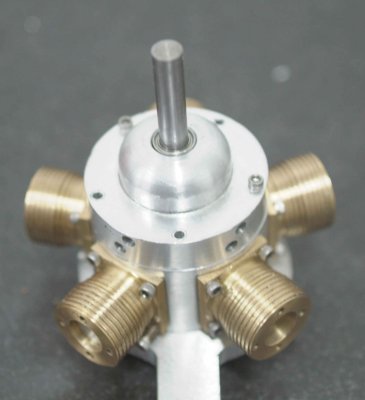
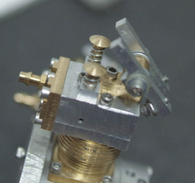
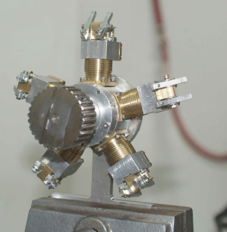
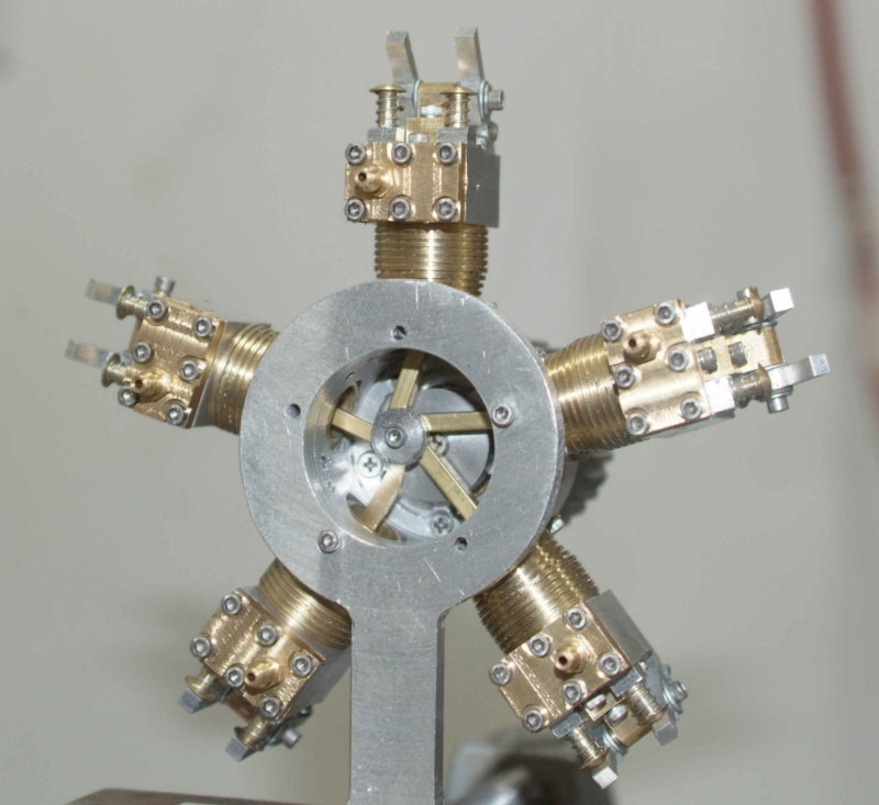
This afternoon I took a short time to attach the pistons to the conrods, and then slide the cylinders over the pistons to attach them to the crankcase:

medium.jpg


medium.jpg


After a bit of twiddling the engine turns very smoothly with finger pressure, 
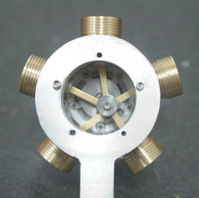
except if the screw for the crank pin is turned down tight, binding the conrods.

I'm pretty sure I know the reason for this. When I milled the crankcase I left the front edge an extra .01" or so from the center line, intending to have room for adjustment later. Well, the time for adjustment has arrived. There are several options for aligning the conrods:

1) Mill a bit off the front of the crankcase
2) Make the crank disk thicker
3) Make the crank pin longer

I think the one I'll choose eventually is none-of-the-above. The next time I disassemble the engine I will make an insert a thin brass washer between the crank pin and the disk.

I don't think leaving the crank pin screw slightly loose is a good option, as the rotation of the engine will tend to cause the screw to tighten.

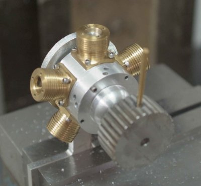
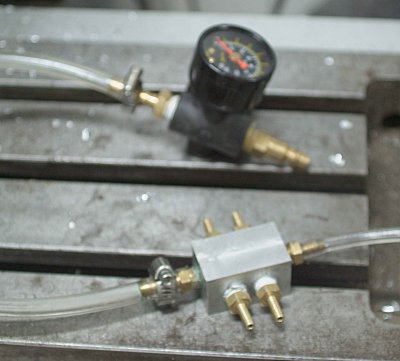
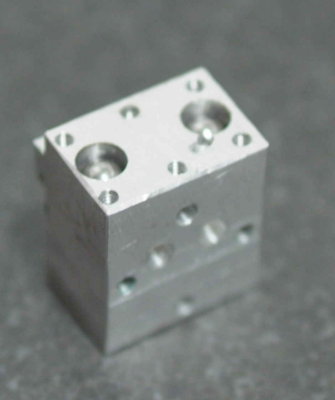
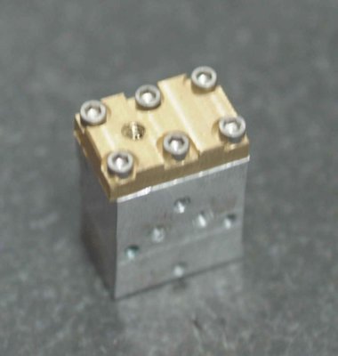
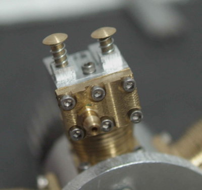
I received a package from Enco today with a supple of 1/4" hose barbs, so I will think about making a manifold to supply air to all 5 cylinders.

I noticed when turning the crank that the pistons expose most of the wrist pins when at their lowest point. It might be a good idea for future builds to make the cylinder spigot slightly longer. That said, the chance of a pin working loose is pretty remote.
 
Kvom--I had to do the same on the radial I built. I used a 0.25" long shoulder bolt as the crank pin, and the hub was 0.25" thick. I didn't want to disassemble everything, so I made a very, very, very thin washer out of brass and put it under the end of the shoulder bolt to free up the hub.---Brian
 
:bow: :bow: :bow:

now it looks like a radial engine! wow, all those parts together in synchronicity :p
 
kvom,

Catching up with things since my moving experience.

I LIKE IT. :bow: :bow:

Best Regards
Bob
 
I have been spending shop time working on the Jeep, but decided to finish a small step on the Halo.

In order to provide a grip to set the timing as well as provide some flywheel effect during tuning, Liney recommends attaching a small weight to the propeller shaft. I had recently gotten a broken driveshaft from an offroad buddy, and decided to use the splined end to make this. I mounted the shaft in the lathe and faced the end, drilled a 1/4" hole, and then sliced off a 1" piece on the bandsaw. I then used the mill to remove the saw marks.

The next step is to provide a means of securing the weight to the shaft. Based on an earlier suggestion, I obtained some #4 lead shot from a shotgun shell. These will be used to press against the shaft. Since the shot measure 1/8" in diameter, I drilled a 1/8" hole through to the center. Given the splines on the sides, the hole was made with a 1/4" endmill to create a flat spot followed by a 1/8" endmill to mill the hole.

medium.jpg


I need a set screw to hold the shot in place, and a 8-32 is the next size up where the tap drill is > 1/8". The particular steel was quite hard to tap, as it feels "sticky". Fearing breaking off my tap, I managed to make only about 4 threads, so I hope these are enough. Here's a shot of the weight mounted on the engine shaft:

medium.jpg


The brass rod was there to tamp down the lead shot into the hold. In didn't have a 8-32 setscrem on hand, so that is another item on the shopping list.
 
To get a runner, I will need to supply air to all 5 cylinders individually. So I made this simple manifold for a small piece of aluminum bar.

medium.jpg


Drilled 3 through holes and threaded the 6 openings 1/4-27 NPT. Then 5 hose barbs for 1/4" plastic tube and ther 6th hole for the regulator line.

The "tuning" instructions are to do each cylinder individually, where you are primarily setting the length of the pushrods so that the input and output valves open and close properly. I realized that I could do this with the tubing attached to all of the cylinders by having only the cylinder being tested have pushrods installed. On a cylinder without pushrods the input valve will be held closed by the air pressure.

This manifold is a temporary fixture; I hope to incorporate a better design into the final design of a stand and base.

We are going offroading tomorrow (snow possible :eek:), so if I don't break anything on the Jeep I might be able to make some more progress on the engine next week.
 
Kvom,
Looking good man. That gets heads and valves?? Oh, I picked up an electronic non wiggler. Man that thing is awesome :bow:M y thank you for turning me on to that. I was going to get one a while ago and I said ahhhhh, it's the same. As I'm sure you know, wow this it is dam accurate tool.

Thanks Again

Tony
 
Despite a list of things I "should" be doing, I spent most of the afternoon doing some fit and assembly of the heads to the cylinders. For any interested onlookers, here's the procedure (just repeat 5 times).

First, place the valve balls into the input (left) and output valve bores.

medium.jpg


I found it tricky to get the depth correct, so before further assembly I tested each visually by pushing the plunger while looking to see that the ball moves upward. If not, the bore is not deep enough. Using a depth mic, I determined how much more was needed to reach the indicated .185". Then I chucked the head in the vise and used a #8 reamer in the mill to deepen it. Mostly I needed around .005" or so.

Next, fasten the valve cover to the head, making sure that the inlet hole is on the left.

medium.jpg


Next the head must be attached to the cylinder. Note that one hole is counterbored do allow the rocker bracket to sit flat. For this reason the bracket is attached after the head.

The plungers are now inserted along with their springs. I cut down the springs to 3 turns to reduce the force on the cams. We'll see if it need more or less when we try to get it to run.

medium.jpg


Finally the rocker bracket and arms are attached.

medium.jpg


With all 5 heads assembled, we have this front view:

large.jpg


And from the rear:

large.jpg


I need to get some more plastic tubing to attach my little manifold, and then cut the pushrods to length before the first trial with air.
 
Really looking good, Kvom. Quite a bit to putting it together, it seems.
Pretty exciting, getting so close to air time!

Dean
 
This afternoon I hooked the manifold to the engine and applied 5 PSI air. As I feared, there is significant leakage around the input valve seats. Of 5 heads, only one seals completely. Three others have smaller leaks (e.g., when I push in the plunger the airflow increases significantly). The last head seems not to seal whatever.

What I should have done, prior to assembly, is test each head's valves. If I insert the balls and apply air, then no air should escape. Similarly, I can turn the valve cover around so that the input barb is over the output valve and test it in the same way. In testing the output, air will still flow out the bottom, but not from the side exhaust hole. Blocking the bottom hole should result in no air flow at all.

So I have made a simple manifold with just one output barb that should make this testing easier. However, when I discover which valves are defective, I'm not too sure I'll be able to fix them.

For other builders, this testing might be appropriate while partially machining the heads. If you drill/ream the plunger holes, drill the valve holes, and drill/tap the valve cover holes, the valves can be tested before doing the rest of the machining of the heads. Just an idea. If I have to remake the heads I will likely test them this way.
 
Thanks to a suggestion to seat the balls in the valve bores (from Cedge and Chuck Foster) by tapping them in with a drift and a hammer, I think I can get the valves to work. I did the first 4 before it was time for dinner and a rest. The seating isn't absolutely perfect in all of them, but hopefully good enough.

I did find a few things for other builders to watch out for. First, the hole for the inlet barb isn't completely over the inlet valve bore, and the threaded portion of the barb is thicker than the valve cover. So when I tightened the barb I got leaks between the cover and the head. So when seating the balls I also gave the inside surfaces a rub with 360 sandpaper and Scotchbrite.

I was also finding a fair amount of small swarf, including some round "wires" that seem to result from the drilling/reaming process. I made sure to pick these out with tweezers and also to blow air through all the passages. I think the wires are burrs created when drilling/reaming the holes for the plungers. I drilled these holes first and the valve bores last, but perhaps the order should be reversed.
 
No one doubts you can fix it. Just a matter of time.

Here's hoping it's very little time.

 
In Looking over the prints for the engine I did not find any reference to the ball. I understand how it will work but one question. Is there springs to push pressure on the ball to seat them?
 
dreeves said:
In Looking over the prints for the engine I did not find any reference to the ball. I understand how it will work but one question. Is there springs to push pressure on the ball to seat them?

Seating is provided by air pressure on both valves. For the input valve the pressure is "direct". When the input valve is open air enters the cylinder and also flows, via the exhaust route, to the output valve, which will be closed.
 
What Dia. Balls are used?
 
Per the plans, the ball needs to fit inside the .200" bore and seat on the .156" bore. I didn't measure but I think they are 3/16".
 

Latest posts

Back
Top