


Generatorgus
Senior Member
- Joined
- Feb 25, 2010
- Messages
- 362
- Reaction score
- 166
I'm not at all sure why I started building this engine.
Machine work on my Wyvern project is complete and all I have remaining to do is reassemble it and spin the flywheel. If the new carb works it would pretty much complete the project.
And then the doubt thing starts to gear up. What if the carb doesn't work, now what, what if this, what if that? Not an earth shaking dilemma, but I tend to obsess a bit. So I decided to do something else.
Winter is creeping in and I was just getting around to putting summers things away. I decided to run my engines one more time before they went on the shelf.
I had the half scale H. Ford running and my thoughts ran to building a new version, modified somewhat from the original design. Next thing I'm digging around and gathering parts for it.
While rummaging pipe fittings I came on a nice older style 3/8” brass tee. Half scale would warrant a 1/2” tee, but I put it with the other parts anyway. After gathering everything I had on hand I started thinking on what other material I might need and went back through the small box I gathered and re-found the 3/8” tee. What if I try making the engine in a smaller scale?
With pencil and paper in hand I started rough plans for a 1/3 scale version of the engine and now I was off on a new adventure.
As is usually my methodology, after some figuring, I'll make a part and if it looks right I'll then figure out what I need for next part. I never have a complete plan, dimensions and such, just build as you go.
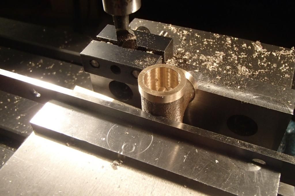
What I had in front of me was the tee fitting, so it went in the mill vise, if it works out I'll try to figure out what to do for the base.
For a casting this fitting was very square, so I chose to hold it with the leg of the tee up.
The rim and bore were machined using a boring tool, then the fitting turned up and the
procedure repeated. The bore was made to fit a piece of steel aircraft tubing that I deemed would be in the range I needed for the cylinder, although I would have to order it.
I used aircraft tubing on the half scale and it worked out good.
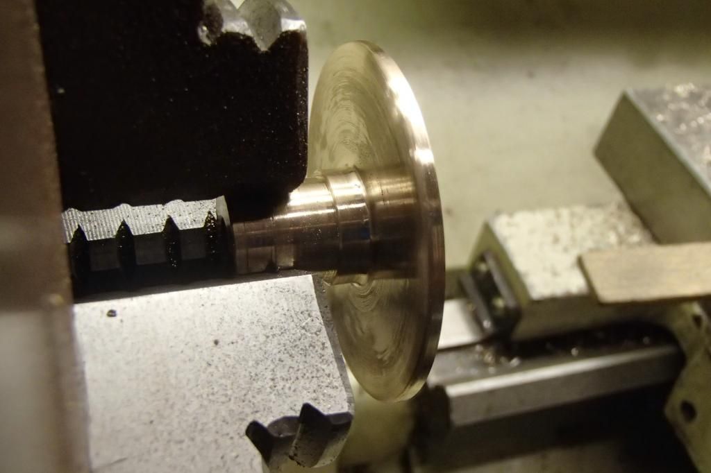
That went well so my attention turned to the next logical part, the base for the tee. The original and my half scale use pipe flanges, but I had nothing on hand and didn't feel like spending any money yet(plenty of opportunities to do that), so I would have to conjure something up.
More rummaging and my attention fell to a partially disassembled 1 1/2”brass globe valve that I bought for about scrap price, just to get the really nice looking hand wheel, thinking I might use it as a flywheel for a model engine.

I already used the stem as bar stock and the disk was still laying inside (I had to search globe valve terminology to come up with disc). It had most of the features I would need for the flange, so a put it in the lathe chuck and started carving to see if the flange was really there.

After a few minutes of carving [FONT=SimHei, monospace]I[/FONT] decided it would nicely.
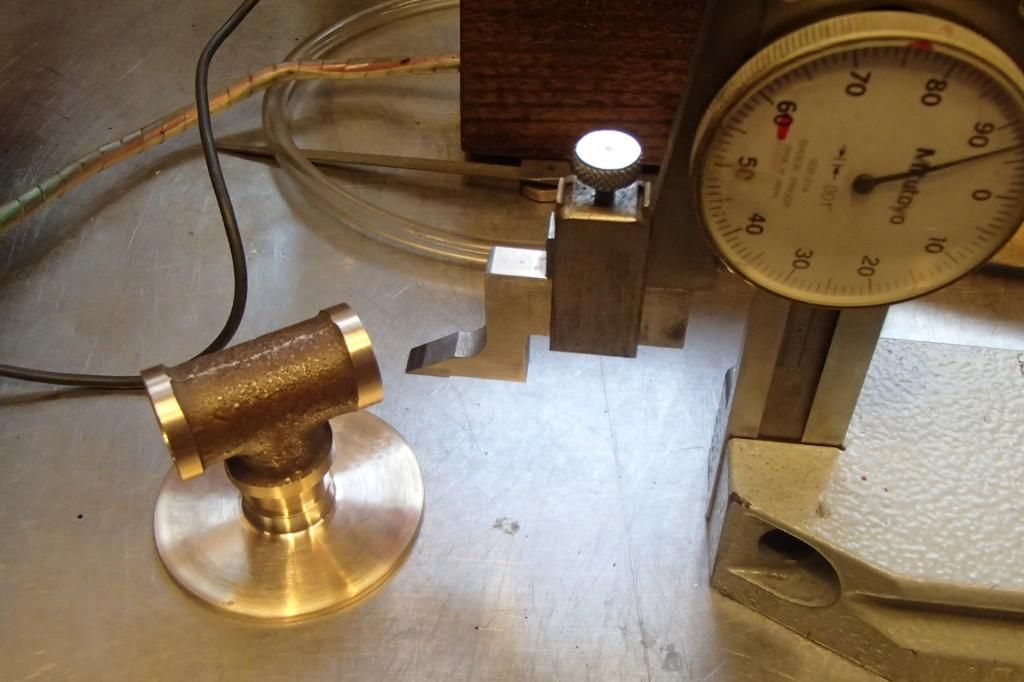
Next in my way of thinking I needed a temporary base to mount the engine and I came up with a piece of yellow pine gleaned from an ancient panel door.
I tend to save wood from things I think may have some use sooner or later, but most eventually get chopped up for kindling. This piece was already in that pile.
I also dug out the hand wheel from the donor valve to see if it was anywhere near right for the flywheel and it looked pretty good visually, but whether or not I could use it is still a question.

I've used hand wheels (valve handles) for some of my electric models before I had any machine tools and they worked, but they always wobbled. There were also questions as to the weight and circumference to answer, so this would be the next to try to figure out.
Flywheel: full scale recommended 12-14 dia ,10-14#
“ “ my ½ scale (hand wheel) 7” dia, 2 lb -6oz
“ “ 1/3 scale (hand wheel) 4 5/8” dia 7.6 oz.
More than likely too small, but I'll try it because I like it. I can always find another project to use it on.
I originally thought the hand wheel I used on the half scale might be too light. It actual had grip knobs cast into the rim, I thought they looked neat, but after getting bruised several times and then had the running engine go to launch mode when it worked it's way off of the bench, I cut the knobs off and re-machined the rim. The substantial loss of weight didn't seem to make much difference.
In the early stages of that build I had both of the knobbed hand wheels mounted side by side, in an effort to get the weight up.

After machining these simple parts, the build is on.
GUS
Machine work on my Wyvern project is complete and all I have remaining to do is reassemble it and spin the flywheel. If the new carb works it would pretty much complete the project.
And then the doubt thing starts to gear up. What if the carb doesn't work, now what, what if this, what if that? Not an earth shaking dilemma, but I tend to obsess a bit. So I decided to do something else.
Winter is creeping in and I was just getting around to putting summers things away. I decided to run my engines one more time before they went on the shelf.
I had the half scale H. Ford running and my thoughts ran to building a new version, modified somewhat from the original design. Next thing I'm digging around and gathering parts for it.
While rummaging pipe fittings I came on a nice older style 3/8” brass tee. Half scale would warrant a 1/2” tee, but I put it with the other parts anyway. After gathering everything I had on hand I started thinking on what other material I might need and went back through the small box I gathered and re-found the 3/8” tee. What if I try making the engine in a smaller scale?
With pencil and paper in hand I started rough plans for a 1/3 scale version of the engine and now I was off on a new adventure.
As is usually my methodology, after some figuring, I'll make a part and if it looks right I'll then figure out what I need for next part. I never have a complete plan, dimensions and such, just build as you go.
What I had in front of me was the tee fitting, so it went in the mill vise, if it works out I'll try to figure out what to do for the base.
For a casting this fitting was very square, so I chose to hold it with the leg of the tee up.
The rim and bore were machined using a boring tool, then the fitting turned up and the
procedure repeated. The bore was made to fit a piece of steel aircraft tubing that I deemed would be in the range I needed for the cylinder, although I would have to order it.
I used aircraft tubing on the half scale and it worked out good.

That went well so my attention turned to the next logical part, the base for the tee. The original and my half scale use pipe flanges, but I had nothing on hand and didn't feel like spending any money yet(plenty of opportunities to do that), so I would have to conjure something up.
More rummaging and my attention fell to a partially disassembled 1 1/2”brass globe valve that I bought for about scrap price, just to get the really nice looking hand wheel, thinking I might use it as a flywheel for a model engine.

I already used the stem as bar stock and the disk was still laying inside (I had to search globe valve terminology to come up with disc). It had most of the features I would need for the flange, so a put it in the lathe chuck and started carving to see if the flange was really there.

After a few minutes of carving [FONT=SimHei, monospace]I[/FONT] decided it would nicely.


Next in my way of thinking I needed a temporary base to mount the engine and I came up with a piece of yellow pine gleaned from an ancient panel door.
I tend to save wood from things I think may have some use sooner or later, but most eventually get chopped up for kindling. This piece was already in that pile.
I also dug out the hand wheel from the donor valve to see if it was anywhere near right for the flywheel and it looked pretty good visually, but whether or not I could use it is still a question.

I've used hand wheels (valve handles) for some of my electric models before I had any machine tools and they worked, but they always wobbled. There were also questions as to the weight and circumference to answer, so this would be the next to try to figure out.
Flywheel: full scale recommended 12-14 dia ,10-14#
“ “ my ½ scale (hand wheel) 7” dia, 2 lb -6oz
“ “ 1/3 scale (hand wheel) 4 5/8” dia 7.6 oz.
More than likely too small, but I'll try it because I like it. I can always find another project to use it on.
I originally thought the hand wheel I used on the half scale might be too light. It actual had grip knobs cast into the rim, I thought they looked neat, but after getting bruised several times and then had the running engine go to launch mode when it worked it's way off of the bench, I cut the knobs off and re-machined the rim. The substantial loss of weight didn't seem to make much difference.
In the early stages of that build I had both of the knobbed hand wheels mounted side by side, in an effort to get the weight up.

After machining these simple parts, the build is on.
GUS
Last edited:


")