Indicator Holders and Such...

Home Model Engine Machinist Forum

Help Support Home Model Engine Machinist Forum:

This site may earn a commission from merchant affiliate links, including eBay, Amazon, and others.
If you need the torque and don't want to fuss with flutes, slap a threaded hole in the middle of an inch or two length of square stock and make a T-handle. They're easily replaceable if they get to be too much of an eyesore.

For a cross-shaped 4-flute knob without an indexer, take some square stock and run a ball end mill down each side. Take over to the lathe, drill, tap, make a little boss and part off. Milling down the center of each face is easier to hang onto in the vise but makes for little ninja-throwing-star shaped knobs. Milling off one corner prevents that, but can get tricky to hang onto unless you leave some un-fluted sections at the ends.


Shred: Now I have a 3rd alternative. Actually, while I may not do this for this little project...it's a good idea for the tip box. Thanks!

Vernon: If that's the nut you were imagining...those are awfully small flutes. They look like they were knurled with a large straight knurler.
 
zeeprogrammer said:
Vernon: If that's the nut you were imagining...those are awfully small flutes.
Not the straight knurl, the turned profile in my post from last night.
The flutes, I imagine more like these:

DinkiDi_006-006.jpg
 
5/8" knob on 1/2" stock. That means the knob will project out only 1/16" on each side of the clamp body. If you think that's enough then go for it.

IMO, the knob should look like a top hat with a 5/8" (or larger) brim and the 'stovepipe' section 1/2" (or a bit less) diameter and at least 3/8" high to lift the knurled/fluted section away from the clamp body.

With these small lathes you'll be well advised to not use a push type knurler. They require a lot of pressure which isn't all that good for the lathe bearings. The tool of choice is the scissor type knurler as shown by DaveW.

If you've done a good job knurling, the diamonds formed will terminate in distinct, sharp points - tactile discomfort. Taking a light skimming cut across the knurled surface will dull these points or, more simply, apply a file (carefully) to make them more finger friendly.

IMO, knurling is ideal for small knobs that are only adjusted occasionally, e.g. the thimble lock on a micrometer. Knobs that are adjusted frequently or require considerable force to be exerted should be fluted for comfort. For knobs that really require some torquing, I, like Shred, prefer T-handles. However, T-handles have those projecting ends that can catch 'stuff' so give some thought to the application before choosing that avenue.

Collets and collet blocks make fluting easier but, lacking those, the whole process can be done simply with a bit of math on the mill...

Clamp the knob in the MM vise with the 'brim' uppermost and center it under your spindle.
Now calculate the coordinates such that a vertically descending endmill will cut suitable scallops into the periphery of the brim.

Example:

N = number of flutes desired
R = radius of workpiece
r = radius of endmill
d = desired depth of flute (d < r)

Define:

S = R + r - d
P = 360/N

Then:

xk = S * cos(k*P)
yk = S * sin(k*P)

for k = 0, 1, 2, ..., N-1

gives the x and y coordinates (relative to center of knob) for cutting each flute.

For your R = 5/16" knob, I would use (but adjust as you wish) something like:

N = 6
r = 1/8"
d = 0.025"

After cutting the flutes, mount the knob in the lathe and chamfer both edges of the 5/8" brim. Debur the curved section of each flute with a hand-held deburring blade.

When I make knobs like this, I always make a few extra and leave them undrilled and untapped. Throw them in the knob drawer and, next time you need one, it's easy to pull one out, mount in the lathe via the 'stovepipe' section, and drill and tap to suit.


mklotz said:
5/8" knob on 1/2" stock. That means the knob will project out only 1/16" on each side of the clamp body.

IMO, the knob should look like a top hat with a 5/8" (or larger) brim and the 'stovepipe' section 1/2" (or a bit less) diameter and at least 3/8" high to lift the knurled/fluted section away from the clamp body.

With these small lathes you'll be well advised to not use a push type knurler. They require a lot of pressure which isn't all that good for the lathe bearings. The tool of choice is the scissor type knurler as shown by DaveW.

I don't know if 5/8 is enough. The fact that it's off the clamp body by 3/8 should help (might even mean I could go smaller). I'll learn one way or the other.

'top hat'...yes...that's the image I was trying to convey.

I have the scissor type knurler.

Now if I could just do some machining...I'm hiding in the closet while dog sitting for one daughter and cat sitting for the other.
 
zeeprogrammer said:
I don't know if 5/8 is enough. The fact that it's off the clamp body by 3/8 should help (might even mean I could go smaller). I'll learn one way or the other.

Just remember it wont be your finger tips doing the action, when you tighten the knobs you will use your thumb and the inside of your "pointy" finger. That skin is what catches on you pant pocket and will remind you for days after why knurls eat skin.

EDIT: tried it didnt ya :)

A 5/8 (3/4) dia set off the clamp like a top hat, with flutes. You can mill the flutes into a length of stock and then work each piece to size. Four flute is harder on the finger as most of the force applied from the "pointy" finger will be applied to just one edge of a flute. Eight flutes will spread it out over 2 or 3.
Tactile Discomfort :) like a new waxed rope over a tall tree. Knurls are fine for small items like the tool post holder, larger and you'll be thinking of testing the ropes discomfort on the designer.

Your issue is its not a "one of" item, that you would tackle without care. Eight of them has you thinking too much. Make one, nail down a process that works for you and make another, repeat as necessary.

Can always just use some 3/4 hex stock, turn down for the "Top hat" effect and use as is. The hex is not so disagreeable to the fingers and you'll escape the milling.

No worse than Xmas toys, some assemble required

EDIT: added shot

If you want to go the real simple and functional, hack of a bolt, drill and tap, and Poof! the thumb wheel is done.

Hacked one out for demo, and I mean hacked :)


z-bracket-a4.jpg
 
Still struggling to figure out how. Maybe I'm looking for a too easy solution. (I like the hex idea...but I don't have the material. Just like previous idea for flutes...I don't have a ball end mill.)

Anyway...thought I'd play at something. Cut a piece of 3/4 round aluminum...A little shoulder...drilled and tapped. Smooth edge but a little rag or pliers should torque it down enough. I hadn't mentioned it earlier...I sawed the slits a little wider...1/16 (Which is probably too big now.) Oh...and the hardware store was closed. Ran by Home Depot and found some 10-32 1 1/4 slot heads. Used those. Still trimmed off the sides to fit the slot on the half joint.

Anyway...the good news...the rods aren't going anywhere. No slip at all.

The bad news...'we' forgot something...
I'm including you all too because 'we' should have known this...

there's nothing stopping the two half joints from rotating on each other.

Bit of a bummer.

Other little bummers include:

a) making the slit a little too big (I think)
b) making the slit not on center
c) also not making either hole on center
d) not using a reamer so hole isn't round
e) settling for slot head bolts
f) slotting all half joints

Upsides include...
uh...include...
include...

a) lot of fun
b) learned a lot

Most important...the tool is still usable. A major goal out of this was to get a tool so I can adjust and tram the mill in preparation for the next engine project.

So...this project is going to be a redo. Need to:
a) figure out flutes
b) figure out round-over tool
c) pay someone else to do it

IMG_0280.jpg

 
zeeprogrammer said:
The bad news...'we' forgot something...
I'm including you all too because 'we' should have known this...

there's nothing stopping the two half joints from rotating on each other.


Most important...the tool is still usable. A major goal out of this was to get a tool so I can adjust and tram the mill in preparation for the next engine project.

So...this project is going to be a redo. Need to:
a) figure out flutes
b) figure out round-over tool
c) pay someone else to do it

A & B good plan
C and ruin all the fun naw

turn your knob piece down so the shoulder fits into the slot. other end of piece.hmm piece of round stock in chuck jaw (10-32 size) set bracket on this piece, set knurler right up to edge of stock with a slight inward angle. rotate stock by hand and put a little radial knurl on the mating surfaces or, use a star washer.

First option also to get fancy if you turn up a little boss on the bracket then the knurl will look much cooler :)

Ok me go back to tranny change now.

Actually liking this post, I need to make some brackets similar to these for tranny cooling line separators. Your giving me all the "Not to do" info :)
 
You don't need a ball-end mill to do flutes if you use the method I detailed in my earlier post. Any old straight endmill will do the trick.

Try a paper washer between the two clamps to prevent them from rotating relative to each other when clamped. Grocery bag paper may work. If not, try a fine grit emory paper.

Actually, I'm a bit surprised that they turn relative to each other that easily. Are you sure you have the knob locked down tightly enough? Put a 10-32 nut in place of the knob and tighten it with a wrench and see if they still slip. If so, a properly designed knob may allow you to provide enough torque to lock things by hand. If not, then consider the paper washers and, in desperation, a lock washer.

There's another, more complicated possibility here. (I'm winging it here but bear with me.) If the two slots aren't fully closed when the rods are gripped then further tightening of the knob isn't providing much force to force the two clamps together (thus increasing the clamp-to-clamp friction that would prevent them from rotating relative to each other). In effect, the two clamp sections in contact can spring away from each other despite the fact that the clamp is tight.

Put a thin washer in each slot such that, when the rod is clamped tight, said washer is also clamped. (The washer has the effect of decreasing the slot width.) Then, further tightening of the clamp will have the effect of forcing the two clamp faces more tightly against each other thus increasing friction.

It may not work but it's a cheap and cheerful experiment to perform. If you don't have thin washers to try, just stick any old (metal) shim in there to see if it works. A Coke can will provide more material than you need and the only tool required will be a pair of scissors.

 
mklotz said:
Try a paper washer between the two clamps to prevent them from rotating

Put a 10-32 nut in place of the knob and tighten it with a wrench and see if they still slip.

Put a thin washer in each slot such that,

but it's a cheap and cheerful experiment to perform.

I'd never heard of experiments being called 'cheerful' before. Good one.

Paper only - nope.
Washers with paper - better - but nope.
Nut - didn't try it...here's what I found (gets kind of obvious)...

Depending on which way you rotate one to the other...it can loosen or tighten...because it puts torque on the nut (knob).

I think too that the clamps, being aluminum, don't provide a lot of friction against each other. (But I don't know enough about metals to suggest an alternative.) And the play knob I have is aluminum too.

I don't like the idea of emery...not sure why...any concern about abrasive material getting loose?

I think there's a fundamental design flaw...or at least...some opportunity for design improvement. Or...maybe we just need a couple of star washers.

You mentioned lock washer. Why lock? For that matter...why or why not star? I understand the bit about wear but otherwise?

Thanks Marv.

Again...this may be 'just a tool' but I know I'm learning a lot and I hope anyone else looking at this thread is finding some useful tidbits.
 
zeeprogrammer said:
I'd never heard of experiments being called 'cheerful' before. Good one.
Ah Fermentation perhaps


Depending on which way you rotate one to the other...it can loosen or tighten...because it puts torque on the nut (knob).


I think there's a fundamental design flaw...or at least...some opportunity for design improvement. Or...maybe we just need a couple of star washers.

Even the commercial varieties, well the less expensive ones suffer that flaw. Like on your mag indicator holder, which is the item being fashioned after, they attempt to increase the holding power by tapering the mating joints. Still tho it will loosen if the rod is turned. Solution, dont bump the rod


z-bracket-a5.jpg


z-bracket-a5.jpg
 
Just saw your post Robert.

Not sure what you mean. The slot is only as wide as the 10-32 hole. So if I turn the shoulder down to fit the slot...the knob won't turn.

I think we'll get this tool to work for what I need for now.

I want to continue the thread though with the idea of doing the tool up right. That's why plans 'a' and 'b'. Need to figure out solution for rotation though.

Couldn't pay someone anyway and I have nothing to trade other than these funny looking 1/2 x 1/2 by 1 blocks of aluminum with a couple of holes and a slit.

Oh...now just saw your second post. True enough about the flaw...but this is so easy that it would make it a real pain to tram with since you have to move the tool.
 
zeeprogrammer said:
Oh...now just saw your second post. True enough about the flaw...but this is so easy that it would make it a real pain to tram with since you have to move the tool.

Like you said earlier probably didnt need to slot all the pieces. Have you flipped one of them around to increase the surface area on the mates? You know flat to flat. With it as your pic shows their is very little surface to surface area, as you dont have all that much to begin with. Take one bracket and just mill down the slotted side smooth, have your knob set against the new flat surface and the other side will give full contact. Cant hurt, a few center punch marks, ah thats getting off the path.

Without a positive locking system its gonna slip if rough handled.

Trannys out, now to go and whittle up some cooling line separators/ holders
 
Foozer said:
Have you flipped one of them around to increase the surface area on the mates? You know flat to flat.

I did. May have helped. But it really comes down to the torque on the knob as the rods are rotated. Rotate the knobs in one direction and it gets pretty tight. I don't think I can get that kind of torque using my fingers on the knob (flutes or not). A bar like shred and Marv suggested would probably work.

But it may very well be that I'm asking too much. I need to flute the knob and see what it gets me.

Thanks.
 
zeeprogrammer said:
I did. May have helped. But it really comes down to the torque on the knob as the rods are rotated. Rotate the knobs in one direction and it gets pretty tight. I don't think I can get that kind of torque using my fingers on the knob (flutes or not). A bar like shred and Marv suggested would probably work.

But it may very well be that I'm asking too much. I need to flute the knob and see what it gets me.

Thanks.

Back to HERE as your original idea. First thought Too many moving parts, second thought, dont say it.

Back in the beginning of this thread are fine examples off what your after, from simple to elegant.

Goal: Set the mill square

Requirements: repeatable and accurate performance

Considerations: Materials, ease of construction, stoutness

Lets say the current path is too full of brambles to continue down, given the above set of conditions what other route do you now see.

All in all tho youve had a good time with this, drilling holes vs reaming, locating holes to center of part, slitting saw work and more fun with nuts and bolts than is allowed sober. Even got the tern Flutes down with so many ways to make the brain hurts. Forget the radial knurling, thats a whole different ball game with its own set of issues.

Your original sketch looks like you planned to leave the spindle in its home position and bring the indicator to the work. The spindle should follow a straight axes throughout its travel (there is a way to check this0 so bringing it down to the work makes the tramming tool design much simpler.

But what do I know, I dropped the tranny out of the car and forgot to disconnect the speedo cable :)

Where too next?
 
Zee

Perhaps you might consider cam-lock type fasteners instead of a fluted knob? These could exert considerably more pressure on the clamp than hand-turning a knob, no matter how many bowls of wheaties or cans of spinach you might have consumed :big:

Joe
 
Foozer said:
Your original sketch looks like you planned to leave the spindle in its home position and bring the indicator to the work. The spindle should follow a straight axes throughout its travel (there is a way to check this0 so bringing it down to the work makes the tramming tool design much simpler.

Not sure I follow. The idea was to tram the mill. I had an idea but also some questions. The idea was to have the spindle at top of Z (is that home?)...table at center X. Then use tool to set indicator to one extreme X of table. Rotate to other extreme of table. Tram as required.

You had mentioned some possible variability in X as the head went up/down. I have no idea what to do about that given the mill I have. Other than to adjust as best I can the Z gib.

One question was whether or not it was useful to move table to extremes of X travel. On one hand I can see how that would be even more accurate...but I don't know if it's necessary. And...what a pain...that's a lot of turning. Plus...I have a feeling I'll never find the proper adjustment if I move the table. (If the Y axis is not locked down, you can actually grab the table by hand and move it back and forth very significantly. There's a whole lot of play.)

Where to next?

Well...I really want to adjust the mill and the lathe and get started on the next engine. But I also want to continue this thread and try and get a satisfactory tool (or tools) out of it.

So far 1 for 1. I'm pretty happy with the stop and what I learned. This 'tramming' tool...as simple as it may be, is turning out to be a pretty good learning thread.

...

So far we've generated some 4 methods to do this. Joe's (the last post here) is another. Thanks Joe! (And I'll pass on the spinach.) Any idea why such notion isn't used on magnetic base indicator holders? Cost? Harder to produce? Or is it used on more quality equipment?

Thanks.
 
zeeprogrammer said:
Not sure I follow. The idea was to tram the mill. I had an idea but also some questions. The idea was to have the spindle at top of Z (is that home?)...table at center X. Then use tool to set indicator to one extreme X of table. Rotate to other extreme of table. Tram as required.

So for this what is needed? and for this it is assumed that the spindle will bring the tool to the work.
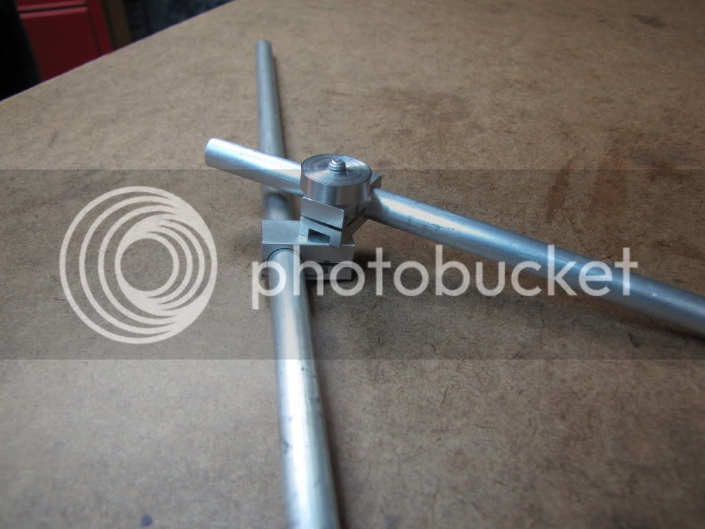
Spindle attachment

Cross Bar

Indicator Holder

Spindle Attachment: depends upon the capacity of the spindle itself, want it to easily attach and stout enough to support the cross bar.

Possibles: A 1/2 dia inch piece of round sturdy steel stock length but lets say 3 inches long. Yours is an X2 variant so were not dealing with monster mills here.

Cross Bar: Given requirement to be able to sweep the tables extremes its max length to be determined by table width divided by two. The longer this piece becomes the more the requirement for robustness becomes.

Question: is the requirement for full table width sweep necessary, would not the half way point from center out serve as well? I.e. 18 inch wide table condition using a 9 inch cross bar, why not use a 4 1/2 inch bar. It is understood that the farther out the sweep is the greater the accuracy upon results, but the shorter bar will still return results better than the accuracy of the machine of topic

Cross bar needs to attach to spindle piece, again this connection point should be simple and secure.

Cross bar needs to be of such size to resist movement

Cross bar needs some method for indicator to attach

Indicator Holder Determined by indicator mount itself, round shaft type or dovetail type. Ease of attachment, firm grip without marring the indicator itself also needs to be considered.


Perhaps more but it is not really that complicated. Dont always catch all the words that fly out at a hundred miles an hour from mental pictures :) Workings of a scatter brain, however you have any new design ideas?

You've re looked over the types in this thread, from simple to not so simple. Given the material you have and the new found lessons give us a sketch.

Genius is the simple solution to a complicated problem, bring the genius out :)

You had mentioned some possible variability in X as the head went up/down. I have no idea what to do about that given the mill I have. Other than to adjust as best I can the Z gib.

There is a way, I cant explain it, it is simple, it is not putting a piece of round stock in the spindle and running it up and down against an indicator, its like the other way around.


So far 1 for 1. I'm pretty happy with the stop and what I learned. This 'tramming' tool...as simple as it may be, is turning out to be a pretty good learning thread.

Should be happy, you learned about levers, such a simple concept older than the hills yet effects virtually every thing mechanical


So far we've generated some 4 methods to do this. Joe's (the last post here) is another. Thanks Joe! (And I'll pass on the spinach.) Any idea why such notion isn't used on magnetic base indicator holders? Cost? Harder to produce? Or is it used on more quality equipment?

Thanks.

Cost

Awaiting your new design

Robert
 
Did a quick rig up...

1st rod in spindle.
2nd rod connected to 1st rod using clamps.
Dial test indicator connected to 2nd rod using clamps.

It's junk. Worthless for tramming the mill.

Big issue...as pointed out by DavesWimshurst...the 3/8 holes won't be round. Not a good hold between rod 1 and 2. A lot of play because only the end of the hole is clamping. Since this is a clamp issue...it's a kill as far as I'm concerned.

For that matter...I'm still not sure how I can get a good tram by moving the DTI from one end of the table to the other. I just don't believe that, even assuming the mill were in perfect tram, that the DTI would give me the same reading. I mean, you breath on it and it changes.

I also think the 3/8 is too small. Not that going bigger (whatever that is) would do any good.

So what to do? Well I'll think on it. But I pretty much know the first thing I'm doing is more research on how people tram their mills.
 
zeeprogrammer said:
Did a quick rig up...

1st rod in spindle.
2nd rod connected to 1st rod using clamps.
Dial test indicator connected to 2nd rod using clamps.

It's junk. Worthless for tramming the mill.

Not a total loss


For that matter...I'm still not sure how I can get a good tram by moving the DTI from one end of the table to the other. I just don't believe that, even assuming the mill were in perfect tram, that the DTI would give me the same reading. I mean, you breath on it and it changes.

Tram is just a fancy term meaning the table is perpendicular to the axis of the spindle, Thats all your doing, but you know that already.

Yup breath on them.. remember what we buy for this hobby are not liquid filled, diamond bearing versions with flux capacitor powered anti-gravity inhibitors. There gonna move if you look at em hard enough, nor are we attempting to achieve a surface flatness down to the millionth so a molecular bond can be achieved between parts. Hobby tools are what they are, we can only do the best we can with what we have.

The tool for checking the bed spindle relationship is nothing more than a right angle triangle. If the alignment is perfect than at every point within the triangles sweep (rotational axis) no gab between triangle and bed will be seen.

Tram tool is just a triangle with all the unnecessary bits cut away. One leg fits the spindle and the other is the cross bar. The stoutness of the cross bar serves as the 3rd leg. Indicator at end just measures any gap that may present it self from point "A" and point "B" So on the X axis you set thfirst point, zero the dial and then rotate the spindle 180 degrees to point "B" any change in dial reading gives the table tilt. Can do the same for the Y axis.

ideally you would want a ZERO deviation between all points, just aint gonna happen. if you can achieve a +/- 0.001 over a 12 inch swing, be happy. Milling that 1 or 2 inch piece at the center of the table you'll never see it. The error reduces towards the center of the swing.

Everyone makes stuff that just doesnt work. Got to keep that sense of humor about ya, just watch MaMa doing her knitting, how many times does an hour or two's worth of work gets the ol unzip do over bit? Just the way it is.

Where are we going daddy? Are we there yet?

EDIT: add

So after reading my own ramblings, I need to make a tool to square off the milling attachment for the lathe. A Monday project and will be using some of your findings in the process, see not a failure at all. Going to make it from the pieces in the photo, hunk of 3/4 inch round AL stock and a broken up end mill bit.


z-bracket-a6.jpg
 
Back
Top