Indicator Holders and Such...

Home Model Engine Machinist Forum

Help Support Home Model Engine Machinist Forum:

This site may earn a commission from merchant affiliate links, including eBay, Amazon, and others.

mklotz

Well-Known Member
Joined
Aug 29, 2007
Messages
3,047
Reaction score
27
Location
LA, CA, USA
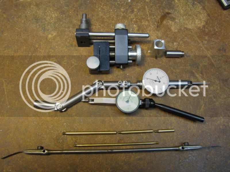
DI = Dial Indicator: plunger operates indicator needle to register motion of plunger.

Used to make direct measurements. A variety of tips are available...

http://www.use-enco.com/CGI/INSRIT?PMAKA=327-2904&PMPXNO=22508034&PARTPG=INLMK3

http://www.use-enco.com/CGI/INSRIT?PMAKA=605-4538&PMPXNO=943849&PARTPG=INLMK3

although you'll eventually want to have a 4-48 tap and die handy to make your own specialized tips and extenders - especially extenders. (A set of 1,2,4" extenders will get you any integer length to 7" - yes, binary works in the workshop.)

Some example tip uses...
ball tip - point contact on a rounded surface
flat tip - eliminate need to put DI exactly on center when measuring to a curved surface on the lathe
wire tip - to measure depths in narrow grooves or down small holes

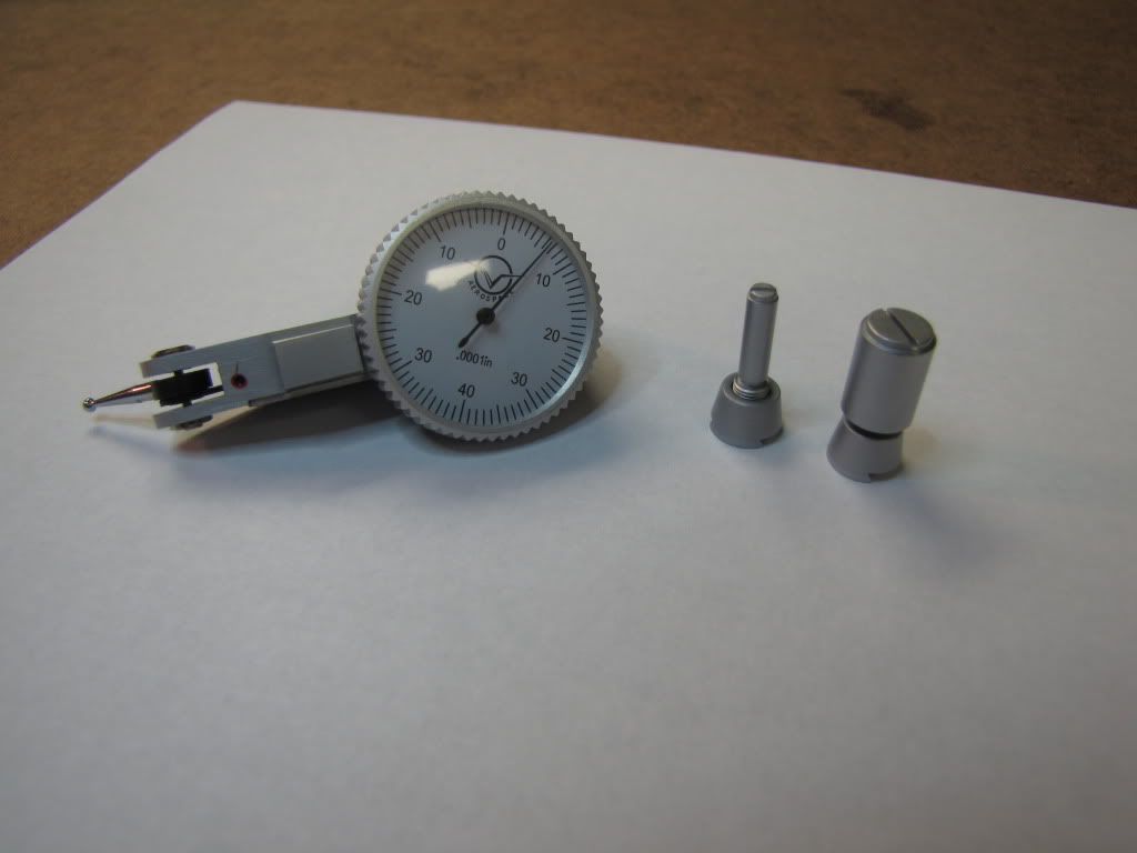
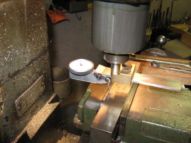
DTI = Dial Test Indicator: A repositionable arm operates the indicator needle to register small increments of motion on the dial.

The variable geometry of the DTI arm makes them generally unsuitable for making actual lineal measurements. As the name suggested, they're used more for comparative measurements such as aligning or tramming. DIs are used for actual measurement (although they can be used for comparison - as in centering work in the 4jaw).

Don't use aluminum rods. Aluminum bends and dents too easily. Steel is a better and cheaper choice. Rather than setscrews use a split clamp drawn together with a SHCS. It will hold the rod more securely and will not mar it. Don't sweat the rust. Don't wash the oil off your hands until you need to use the restroom. :) The oil transfer will keep them from rusting.

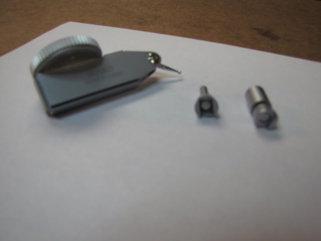
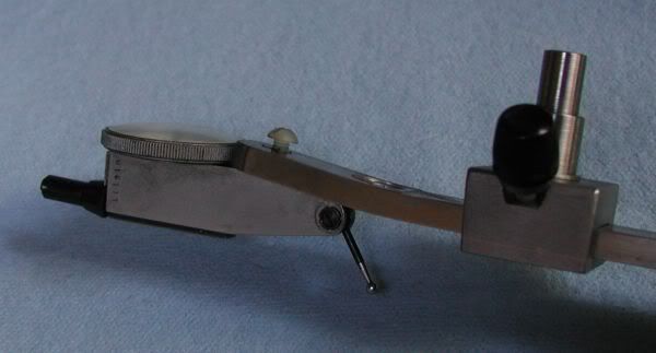
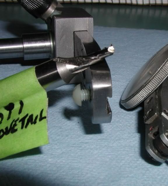
Think about how you will attach the DTI. A picture of your DTI and the dovetail attachments you have for it will be useful in this discussion.

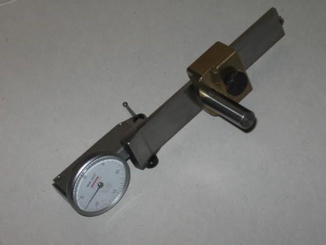
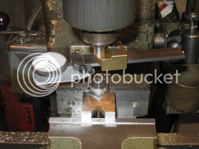
The block-and-arm design you describe will be useful for tramming the head where you need some sweep but it may not be the best thing for "in-close" jobs like centering on a hole.
I have a simple design that I built a long time ago. I'll try to take some pictures tomorrow and put them up. Plus there's my magnetic design which you've seen.

Does your DTI have a pin mount in addition to the dovetails? If it does, a simple chunk that can be gripped in the chuck with a series of offset holes may be all you need.

Whatever you design, try to ensure that it doesn't take up much z-axis headroom.

More when you've digested what I've said here...

 
zeeprogrammer said:
This thread is about making some adjustable clamps and rods. Primarily for holding indicators and the like. My first pressing need (aside from the aforementioned back problem) is to be able to do a better job of tramming my mini-mill.

Simple? An obvious issue to me are the set screws. Over time they'll ruin the rods. But I may not care (at least initially) because usage should be low.

And gee...if I'm doing this...maybe some proper drawings would be good. What would anyone suggest as a freebie drawing software?

tram, tramming, indicator holder,

HERE For one version of a tramming tool.

Clamp type mount, more time to make but better in the long run.

Google's Sketchup is good for drawings or placing ideas upon paper. It made the flywheel to the left.

Funky version for the drill press, once in a while I try to drill a straight hole :) Just a 3/4 inch round stock 'bout 6 inch long. Need a mirror to read the opposite side so a dual mount sounds better and perhaps easier all the time

And large garbage bag over shop tools keeps the dust off the workings


tram-a1.jpg
 
mklotz said:
Don't sweat the rust. Don't wash the oil off your hands until you need to use the restroom. :) The oil transfer will keep them from rusting.

The hands!? :big:

mklotz said:
A picture of your DTI and the dovetail attachments you have for it will be useful in this discussion.

Not the best...but for starting out it should be sufficient...

IMG_0246.jpg

IMG_0247.jpg

Sorry for the blurriness of the 2nd pic.
You can see the dovetail on the DTI...one on top and the other along the back. The 'holder's are 3/8" and 0.155" (I'm thinking 4mm?).

mklotz said:
I have a simple design that I built a long time ago. I'll try to take some pictures tomorrow and put them up. Plus there's my magnetic design which you've seen.

Please do. I saw your magnetic design again tonight. I'm in the process of going through the 'launch engine thread' and picking out some learnings and ideas.

mklotz said:
Does your DTI have a pin mount in addition to the dovetails? If it does, a simple chunk that can be gripped in the chuck with a series of offset holes may be all you need.

I don't know what a pin mount is unless it's the 'holders' I mentioned earlier. In which case...they're pin mounts.

mklotz said:
More when you've digested what I've said here...

Anybody got some tums?

I agree (of course I do) that steel rods would be better. Also split clamps. My only concern with split clamps (which I'm sure will have been addressed) is size. I'd like to keep the clamping blocks as small as possible.

Thanks Marv. I look forward to the pics.
 
Foozer said:
For one version of a tramming tool.

I'll have to go back to that thread. It looks really great. I was surprised at some of the avatars and members. I hadn't seen them before. But the tramming tool looks very good. The only thing is...it requires two indicators and seems like a specialized tool. I suspect having two indicators isn't a big deal...I...the newbie...have a couple or three. Maybe the specialized tool isn't a big deal either. Just a bar of aluminum and some rod. And the importance of proper tramming probably warrants it. (Again, as spoken from a non-machinist.)

Foozer said:
Google's Sketchup is good for drawings or placing ideas upon paper.

I think I've tried that. Might have been my own setup...but I had trouble. (Hm...I might be able to get something from a mechie at work. He owes me. "Never be the lendee...always the lender."...Rats. Shouldn't have said that...I owe big time to this forum.)[/quote]
 
zeeprogrammer said:
I'll have to go back to that thread. It looks really great. I was surprised at some of the avatars and members. I hadn't seen them before. But the tramming tool looks very good. The only thing is...it requires two indicators and seems like a specialized tool.

Specialized, yes, for the mill. Two indicators so you dont have to crane the neck around to read the single gauge that presents its back side to you after the 180 tool rotation. So cure is, two dials giving both sides of center readings. Indicator prices run all over the board, again price them according to need, this is a hobby and regardless of price they do break.

I think I've tried that. Might have been my own setup...but I had trouble. (Hm...I might be able to get something from a mechie at work. He owes me. "Never be the lendee...always the lender."...Rats. Shouldn't have said that...I owe big time to this forum.)

Sketchup is fairly easy to pick up. hass a little built in "Instructor" that explains what the icon do and associated hot key options. Not exactly a cad program, but it free.

I think that board is a sister board to here. many members are common to both
 
Carl,
This may be a little more than you may want to tackle now but I have found this holder to be very useful on a small mill

IMG_0391.jpg


It appeared in Machinist's Workshop April/May 2001. It requires very little extra room to use compared to the usual coax device

Here it is setup to center a round part under the spindle:

IMG_0389.jpg

It is swept round the part rotating the spindle by hand.

Here it is used to check the parallelism of my vice, the spindle remaining stationary:

IMG_0390.jpg


It can also be used to tram the spindle when extended. I use a flat plate to span over the table slots.
Dave
 
Zee,
When you have the indicator in the spindle make sure you remove it when you are done. I turned the mill on, not thinking, and before I could hit the e-stop it went out to parts unknown. Sometimes I get so hung up on the adjustment that I forget the reason I'm there! :eek:

This may not have happened to everyone but I bet I'm not the only one to send an indicator flying.

A tool I made for tramming was a piece of drill rod, .750 that fits in my collet, cross drilled .375. I cut a piece of bar stock to fit the hole and a bolt to go in the bottom of the drill rod to hold the .375 rod. I can extend my dial inicator out about 12 inches to sweep the far ends of the table. I attach my DI and take a reading to my left. I zero the indicator. I pull up on the rod so I don't hit the t slots and rotate to the same position on the right side. Since the DI is facing away I go around the table and read the DI. The change in reading is my out of tram. I adjust the head to half of the reading, rezero and check again.

Do this until the left and right agree. You are checking the spindle rotation to the mill bed. I hope this doesn't seem like "teaching my elders to suck eggs" but if someone had explained it this way I would have caught on quicker. I used to put a DI in the spindle and run the x axis all the way from one side to the other and this told me nothing!

When I am close I snug up the bolts and tap with a dead blow hammer. Watch out for final torque as you can move the head with bolt torque. (this applies to a bridgeport type mill. I don't know what adjustments you may have but the measuring is the same, rotation planar with the table).

Flycutting will really tell you the tram. When it is "on" you will get an overlapping or "moire" pattern on your work piece. If it is off you will only cut on one side or the other.

Hope that helps,
Sean
 
Dave,

That looks pretty useful.

Looks like it mounts by the dovetail? (I hadn't noticed the bit of dovetail on that side of the DTI. Lesson: Carefully inspect everything about a new tool.)

You mentioned turning the spindle by hand. On my mini-mill, when I do that, you can feel a kind of 'cogging' action. I'm not sure that's the right term to use. The spindle wants to settle at a spot every few degrees. It made finding the center on my RT a little difficult.

Does anyone else have a mill that does that? Is this a problem I should be looking at?

Thanks Dave.

Sean,

You description of tramming is what I want to do.

I did the X table thing too. Luckily, I also realized 'huh?'. My next method was a 1-2-3 block and raising/lowering the head. My third attempt was taking a dial indicator mounting system (magnetic base) apart and mounting it on the head to be used similar to what you described. Better still...but not satisfactory. Hence I'm here.

Yes, from what I've read, flycutting seems to be a very good test. You might recall that I did a flycut on the Launch Engine project. That's what told me the tram was still off.

Thanks Sean.


zeeprogrammer said:
Dave,

That looks pretty useful.

Looks like it mounts by the dovetail? (I hadn't noticed the bit of dovetail on that side of the DTI. Lesson: Carefully inspect everything about a new tool.)

You mentioned turning the spindle by hand. On my mini-mill, when I do that, you can feel a kind of 'cogging' action. I'm not sure that's the right term to use. The spindle wants to settle at a spot every few degrees. It made finding the center on my RT a little difficult.

A Sieg X2 type. Your mill looks like its spindle is gear driven, should be rather free turning. I see better with my ears than my eyes so without hearing what the mill sounds like when running first thought is tight gears, bearing issue. Also see a preload nut on the spindle assembly inside the housing. 'Fraid to say you may need to disassemble, clean, lube, and adjust the top end.

You description of tramming is what I want to do.

Yup, your checking the sides of a triangle basically, Fixed length is the spindle axis, the deck plane and indicator point make the other two sides which vary in relationship to the out of level condition. Pick a point "A" on the deck and zero the dial. One triangle, rotate the spindle 180 degrees and if new triangle equals the first then the dial will be still at zero, if not then adjust as required to achieve equal triangles.

This is only good if the spindle does not follow a "S" pattern as it travels up and down (best I describe it) There is another method to check that the spindle follows axis within its travel but that is best left to someone with better writing skills. I'll only get you confused :)

Little sketchup pic of Seanol's tram tool

tram-a2.jpg
 
Bogs' two DI tramming device is way too difficult a project for a novice. Think through how that thing works and how it's calibrated and you'll understand that it requires some very precise machining to be a useful tool. Bogs has the skills to make it work but he's been at this since the early Jurassic. This isn't a project for Carl - at least not yet.

DaveW's offering (or something very like it) is much, much better. It's simple, rigid, requires no high precision machining, takes up very little headroom and capitalizes on the the style of DTI Carl owns to make the dial easily visible in all orientations. Plenty of swing for tramming the head yet it can get in close for centering small holes/cylinders. The only thing I would add to it is the ability to mount the DTI facing outboard for a little greater reach (maybe that's present in Dave's design - I can't tell from the photo.)

For mounting your DTI to the sliding bar that Dave shows, all you need to do is drill some holes in various orientations to accept one of your dovetail mounts, add a setscrew to lock it in place, and voila - no need to machine dovetails.

Carl, please notice that these devices need a spigot with stepped diameters for mounting in the mill. (You can see it in the pictures of my magnetic one. Dave's doesn't but I would add the feature if I were copying his design.) That's an important feature if you have collets for the mill. (Can't remember offhand if you do but, even if you don't, you will.) You don't want to be changing out collets every time you want to use this device. Since the most likely collets to be in place when milling match the common endmill diameters - 1/4, 3/8, 1/2 - you should make your mounting spigot to have those diameters.
 
Foozer,
You nailed it. I haven't made a stepped arbor because I always seem to use a .750 collet!

That is definitely a good idea and it will help you hit those diameters in the late. Good practice.

Thanks for the idea Marv, and the requisite practice it will take...

Sean
 
Foozer:

There's free turning and there's free turning. Too subjective for me to know. I'll try to take a video this evening for sound and action.

The 'S' pattern seems scary. If anyone has something on this...

Marv:

Re: two DI...I agree.

Any reason why I couldn't/shouldn't build something like Dave's but with the rods and clamping blocks I introduced the thread with? I think Dave's suggestion is great for 'close' work...mounting vise/RT, etc. But it doesn't seem to have the reach for tramming. Different lengths rods would give me different options.

In any case...you suggested using steel rather than aluminum. As one would expect...I have little knowledge here. You had mentioned in another thread that 1018 doesn't give the best finish but I don't think I'm looking for that here. Any other suggestions? Or better...point me to a thread or source that discusses metals. I also see that 12L14 seems to be popular.

Re: the stepped spigot...depending on the collet, wouldn't that limit the Z available? That is, a small collet would have more of the spigot sticking out? (And just how high should each step be?) What about 'removable' spigots of different diameters?

Let me know about the metal...I'd like to order some. I have a little time...need to sketch up what I think will do.

Thanks all.


Yes, you could use your aluminum blocks and rods. I'd still like to see split clamps rather than setscrews for rigidity but it's your tool, make it to your specs. Again, the objective is to learn about design planning when building something from scratch. You'll find that tools, like engine parts, get rebuilt as your learning and sophistication matures.

Regular old CRS (1018) would be fine for this application. You won't be doing much milling on it - just clean up the ends. Dark, sulfurized cutting oil will improve the finish and the odor is real shop perfume - not as sexy as Hoppe's #9 but it will get you noticed. :)

12L14 ('L' for Lead) contains lead which makes it machine like butter to a beautiful finish. Get some so you can hands-on experience just how nice it is to work with it. Its one drawback is that it rusts easily. Even here in semi-desert LA, I have to keep certain pieces well-oiled to prevent rust.

Yes, the stepped spigot will eat up a little bit of z room using a small collet. I don't find it a problem on my mill but your situation may be different. Remember, this tool will (hopefully) never see any significant forces so the steps don't have to be that high - a light grip is all that's needed. IIRC, mine are 1/2".

If you're concerned, make a stepped spigot that screws into your DTI holder. If it turns out to be a problem, you can make dedicated, single diameter spigots that screw into the same threaded hole.

Preemptory hint: Now that you're wandering into the heady world of tool building, make a decision to standardize on a few screw sizes you will use. In the future you'll be happy to be able to synergistically pull a part off one tool and have it mesh with an existing hole on another tool. I use 4-40, 10-32 and 1/4-20 wherever the choice isn't driven by some other consideration. Painting the Allen wrenches that fit these sizes with a color code saves me lots of time finding the right wrench.
 
zeeprogrammer said:
Foozer:

There's free turning and there's free turning. Too subjective for me to know. I'll try to take a video this evening for sound and action.

If your high/low lever, assuming its not a belt drive version has a neutral or will allow the spindle to rotate without engaging the gears try that, turn spindle by hand and see if the "cogging" goes away. The bearings should be of the sealed type, so that reduces the chip in bearing odds. Spindle bearing would really have to be preloaded to excess (as far as I can tell from the parts breakdown) to get the bearing to behave like you describe. Picture the race of the bearing having just a small defect. As the inner balls rotate around (room for remake here) the preload causes the smaller ones to 'bump' the defect. Would be an even spaced feel to it. May or may not make noise and the normal gear noise probably mask it over anyway. Dont worry about it to much. I replaced the bearings in my drill press with some of better quality for much the same "cogging" Actually getting off thread here but what the hey, can delete it later :)
 
Another thanks to Dave for posting his dti holder.
Copied it. Was able to grind a dovetail flycutter from old 2 flute end mill. Ground off of one flute and eye balled a dovetail on the other. Took less then 2 minutes and got close enough to use on first try.
dtiholder004.jpg

dtiholder007.jpg
 
DTIs, DIs and stuff...

DTI.jpg


On the top is the Chinese knockoff of the Zero-It along with a homemade dovetailed holder that accepts the cylindrical fitting (next to it) that screws into the indicator below.

Next below is a simple DTI holder I made early in my career - I had a lot to learn about tool design. It still has its uses but it's far inferior to the one above, my magnetic one and, especially, DaveW's pictured earlier in this thread. It's still useful for tramming the tailstock in the lathe.

Below that is a commercial one (ENCO, IIRC) with a dovetail fitting that holds a DTI at any angle but lacks the ability to do large translational offsets.

Below that are three brass extenders for DIs (not DTIs). Each has a male 4-48 thread at one end and a female at the other. They can be used individually or ganged together in various ways to make a needed length. Very handy.

Below that is another brass extender with male threads at both ends made for some now-forgotten purpose. When making special points for a DI, it's easier to tap a hole than form a male threaded stud so having a male-male extender saves a bit of time.

Finally is a finger saver. I inherited it from a deceased machinist. It's nothing more than a long steel rod with finger clamps at both ends. It's used to hold cigarette papers or bits of shim stock in places where you don't want to (or physically can't) put your fingers. I use it often to zero an endmill onto a part when I don't want the mill to mar an already finished surface. Bring the endmill down on the shim stock and zero the 'z' axis DI with a suitable allowance for the thickness of the shim.
 
mklotz said:
Yes, you could use your aluminum blocks and rods. I'd still like to see split clamps rather than setscrews for rigidity
No no. Was just thinking rods and blocks...not necessarily type of blocks. I have to play with some designs.

mklotz said:
Dark, sulfurized cutting oil will improve the finish and the odor is real shop perfume - not as sexy as Hoppe's #9 but it will get you noticed.

Fine. So long as it's not one of you. Someone needs to come up with a marketing scheme that shows guys who smell of this stuff are the cat's meow.

mklotz said:
Now that you're wandering...

Uh oh.

So I'll order some steel tonight. Also some fastners...I have virtually nothing.

Foozer: No not off the thread...even though it's about 'Indicator Holders and Such..." it's really another learning thread (ha...all my threads are learning threads).

Here's some videos...

This one shows what I meant by 'cogging'. You can feel a definite 'cog'. I don't feel this on the lathe. But the lathe is belt driven and I haven't looked closely at the mill. I'm remembering other threads that talk about modifying this part of the mill (i.e. replacing the gears?).


Here's low gear...


Here's high gear...


Here's what seems to be neutral...(i.e. no engagement)...


My (inexperienced) guess is that I'm okay. That it's a matter of whether I want to do the mod. My understanding is that the gears may/will eventually break...that's when I'll do it.

ghart3: Thanks for the pics. Very helpful.

Marv: Thanks for the examples. And I really like the 'finger saver'.

Thanks all.
 
zeeprogrammer said:
Foozer: No not off the thread...even though it's about 'Indicator Holders and Such..." it's really another learning thread (ha...all my threads are learning threads).

Here's some videos...

This one shows what I meant by 'cogging'. You can feel a definite 'cog'. I don't feel this on the lathe. But the lathe is belt driven and I haven't looked closely at the mill. I'm remembering other threads that talk about modifying this part of the mill (i.e. replacing the gears?).

That cogging is something loose in the head stock, sounds like its tapping the case. can hear it when you turn the motor on, starts as the tink tink and grows to a growl as the speed increases. has normal motor whine, the higher pitch even sound. Me I'd be taking that head unit down to the work bench (with a copy of the exploded parts list) and find that rattle before it finds you.
From the units HF 44991 PDF it looks to be a rather straightforward assembly. You should be able to verify the internals with little problem. Not much inside that moves around other than the Hi/Low mechanism. Almost sounds like it is the rattle, but. In any event a teardown, not a hard thing to do, will find it. The fixing pin is out? Right?

I get a sound like that from the lathe when the backgear engagement pin comes loose. Cost me a backgear for not giving the sound it due :)

HERE for a shot of the internals should be similar

Last edit If you want to see what the machine is doing Stick a glass of water on the bed and turn the machine on. The various vibrations will leave ribbles on the water surface. The motor should leave a nice even pattern, smoother the motor the smoother the water surface. Something out of balance or knocking about will give you larger ripples, Plus it will tell you how well the machine is leveled by watching the center of the ripples dance around the center of the cup. If nothing else its cheap entertainment.
 
Foozer said:
Me I'd be taking that head unit down to the work bench (with a copy of the exploded parts list) and find that rattle before it finds you.

Whew...I was worried for a moment. I was trying to find 'Fixing Pin' and came across a table that called it out but the drawing next to it, didn't show it. I was about to ask what the heck it is. A few drawings later, I found it. The thingie (i.e. Fixing Pin) to 'lock' the spindle when tightening or loosening the draw bar. So yes...it was not in place. The spindle would not move unless you were thinking it wasn't fully seated. But no...it's sitting on the table.

So....I guess I'd better take the thing apart. I should get a better understanding of the equipment anyway. That's probably a weekend job. Thanks.

Just to be sure...you're thinking it should turn round-and-round just like the lathe's spindle? Pretty smoothly?

Thanks Robert.
 
zeeprogrammer said:
So....I guess I'd better take the thing apart. I should get a better understanding of the equipment anyway. That's probably a weekend job. Thanks.

Just to be sure...you're thinking it should turn round-and-round just like the lathe's spindle? Pretty smoothly?

Thanks Robert.

I would expect some gear noise, but thats a relatively even sound, a broken tooth on a metal gear might announce itself, but that "Tink" is hollering for attention. That doesn't belong there. By you video description you indicate a binding and then the tink sound. Its not in the spindle for the sound is the same in neutral.

Getting familiar with the internals is something your gonna have to do anyway, you can use the screwdriver to ear bit to locate the sound. Power off the mill, place one end of screwdriver (big end) to ear, turn spindle by hand and move tip of screwdriver around case to find the source. Stethoscope bit.

One good thing about your video others here have the same or similar unit, you should be getting feedback on that sound soon enough. And here you thought turning metal was all that the hobby required :)

Some assembly required, batteries not included
 
Back
Top