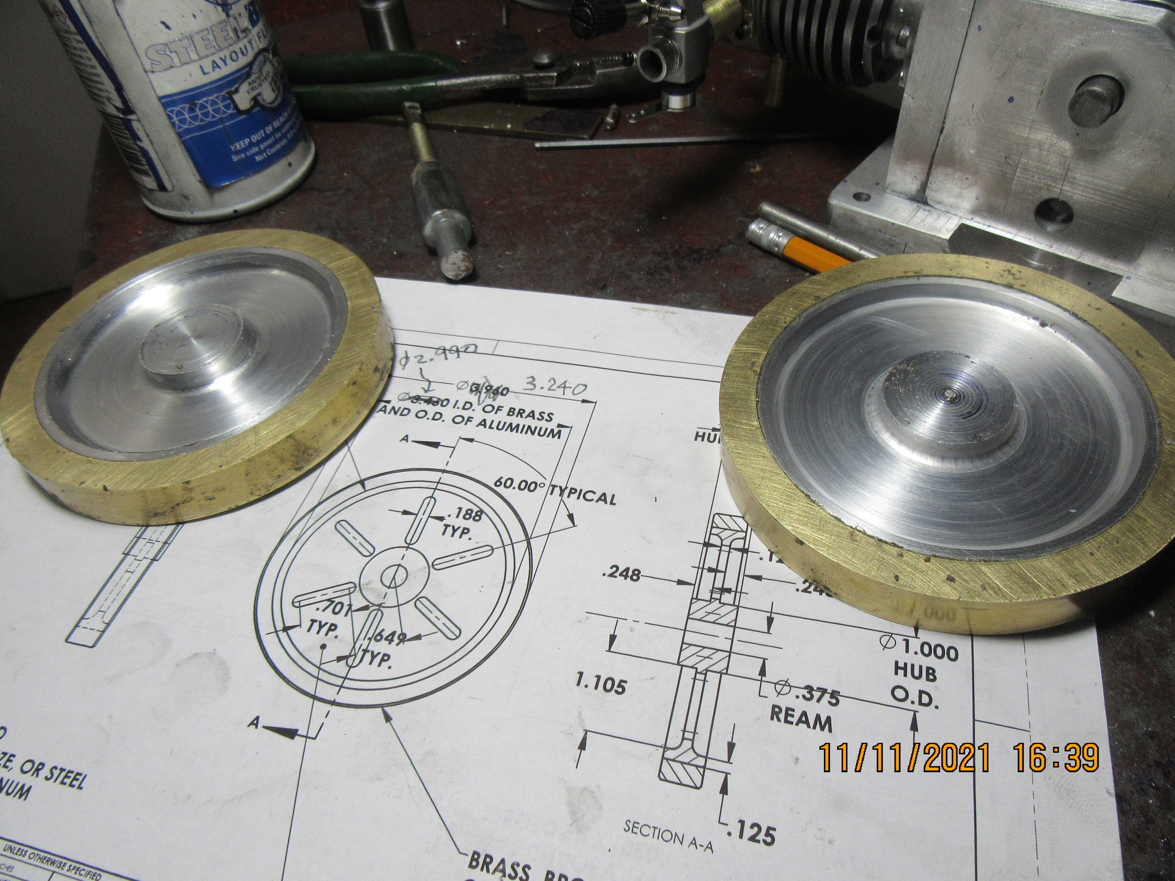
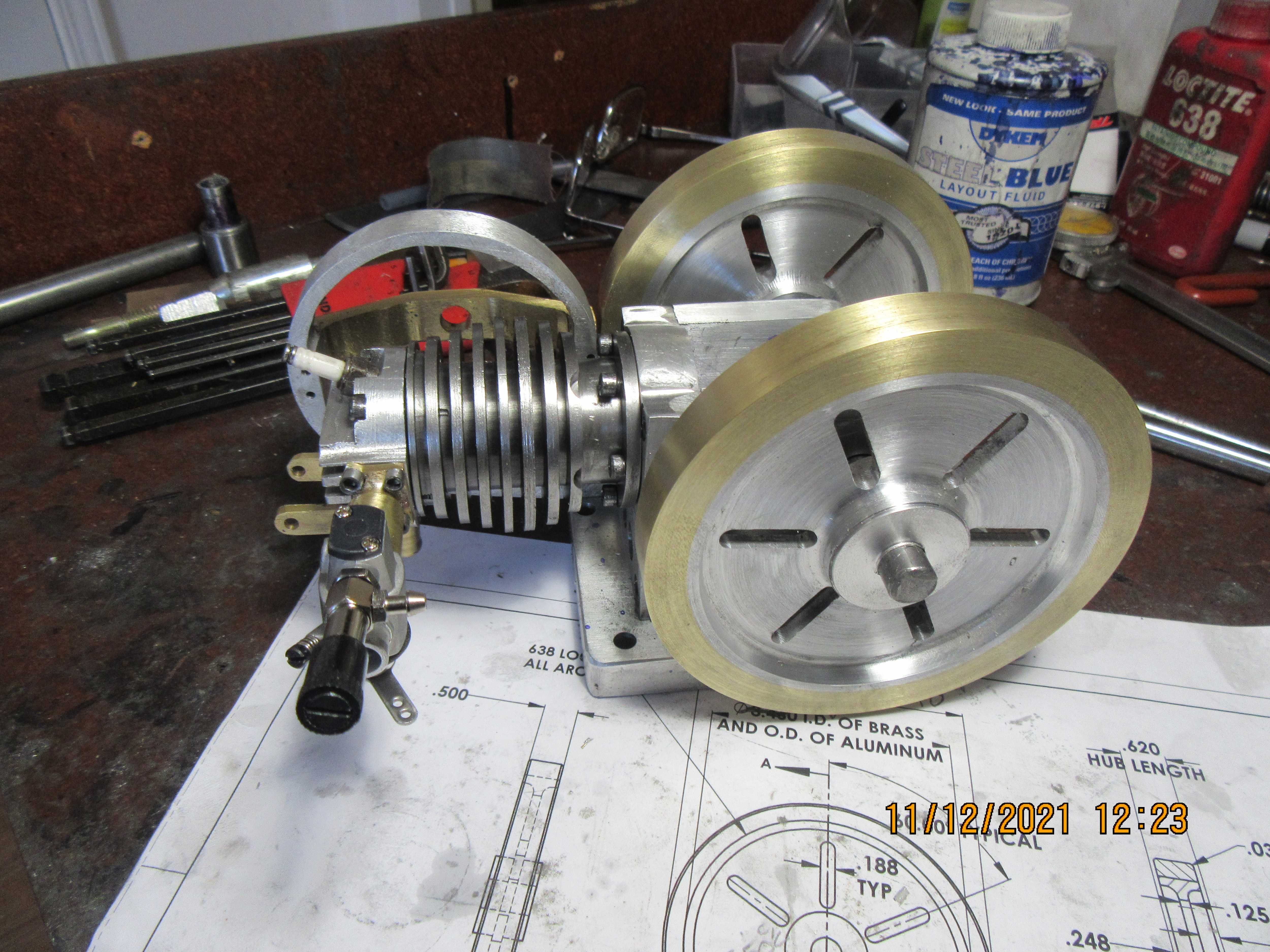
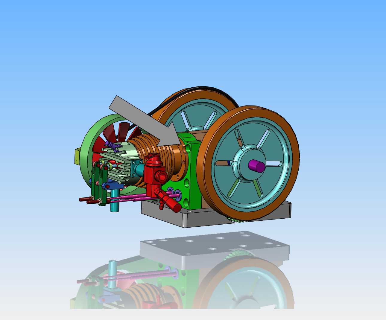
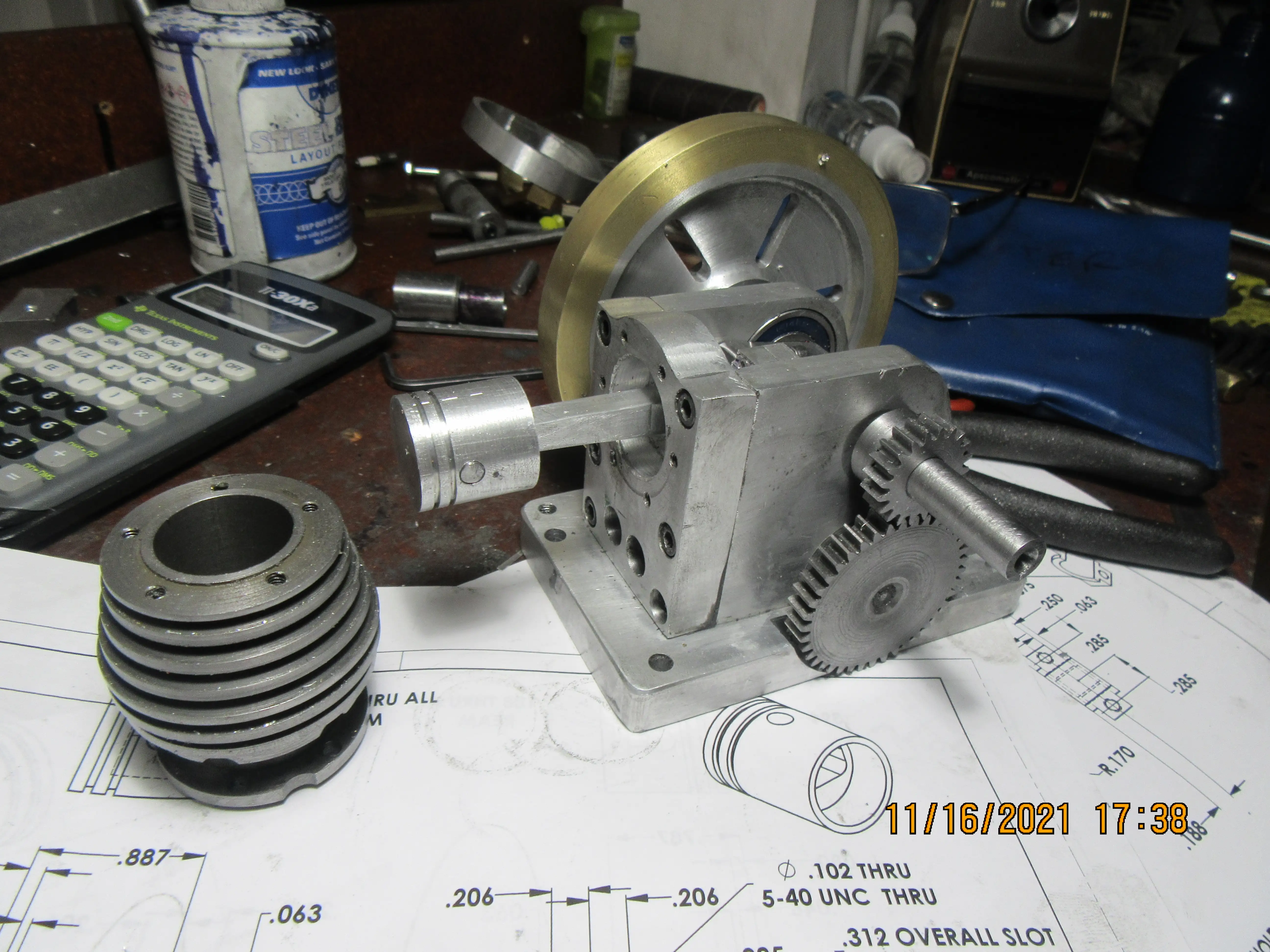
Today I did something for the very first time!!! Those reliefs in the face of each flywheel are 3/16" deep, and they have a 1/8" radius in the corners. I have always known that there should be radius there. I know the whole tune about sharp inside corners causing stress risers and are more apt to fracture in use. It's just that I never actually did it before. I have about 40 engines running just fine without a radius in the corners of the flywheels. Today I actually ground an HSS tool and machined the radius. The outer brass rims are loctited to the inner aluminum flywheel body (That's why they look dirty--that dirt will all come off with a "clean up" pass in the lathe.) Drilling and reaming the center hole for the shaft is one of the last things I will do.