Horizontal Air Cooled Engine

Home Model Engine Machinist Forum

Help Support Home Model Engine Machinist Forum:

This site may earn a commission from merchant affiliate links, including eBay, Amazon, and others.
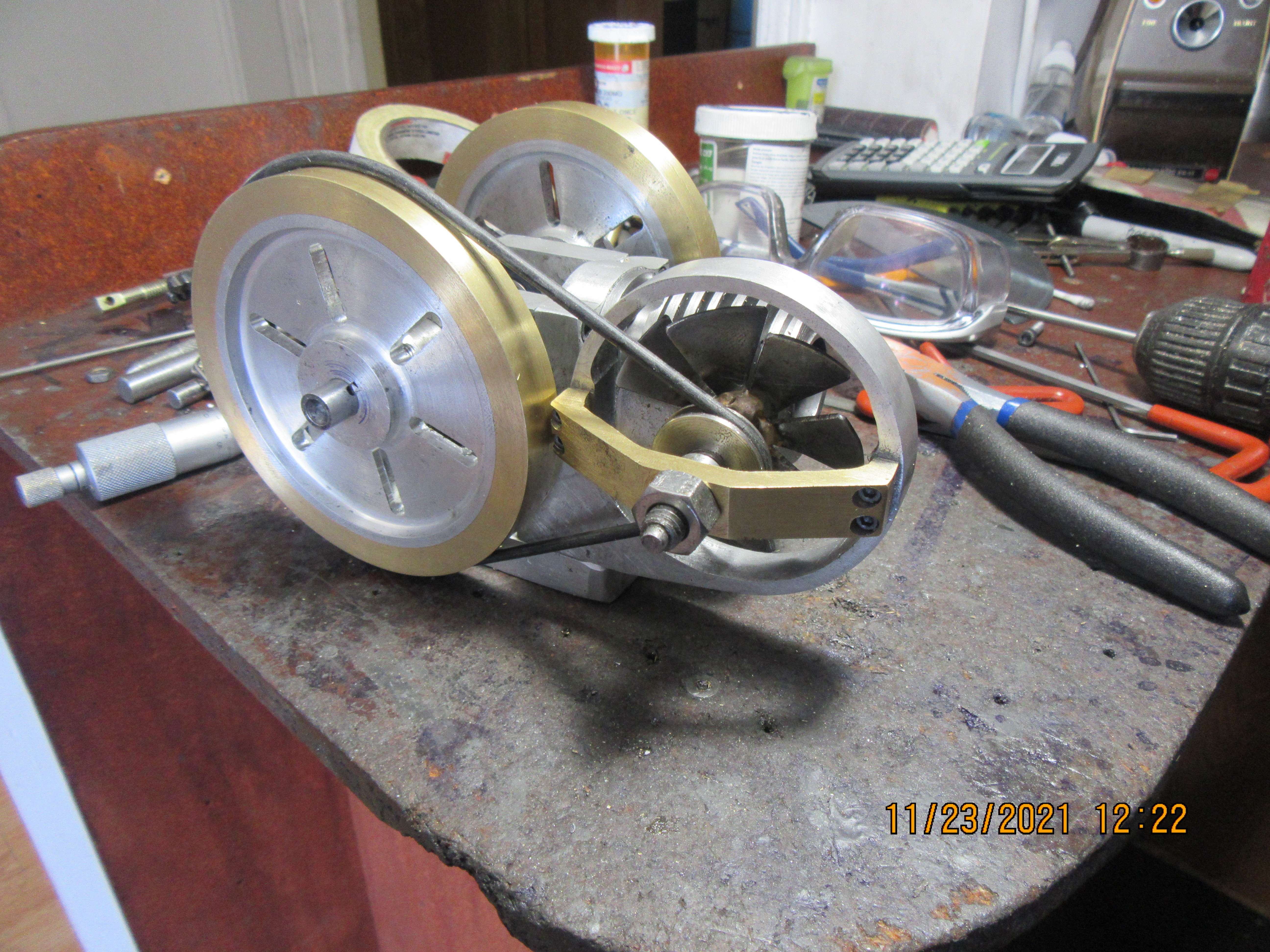
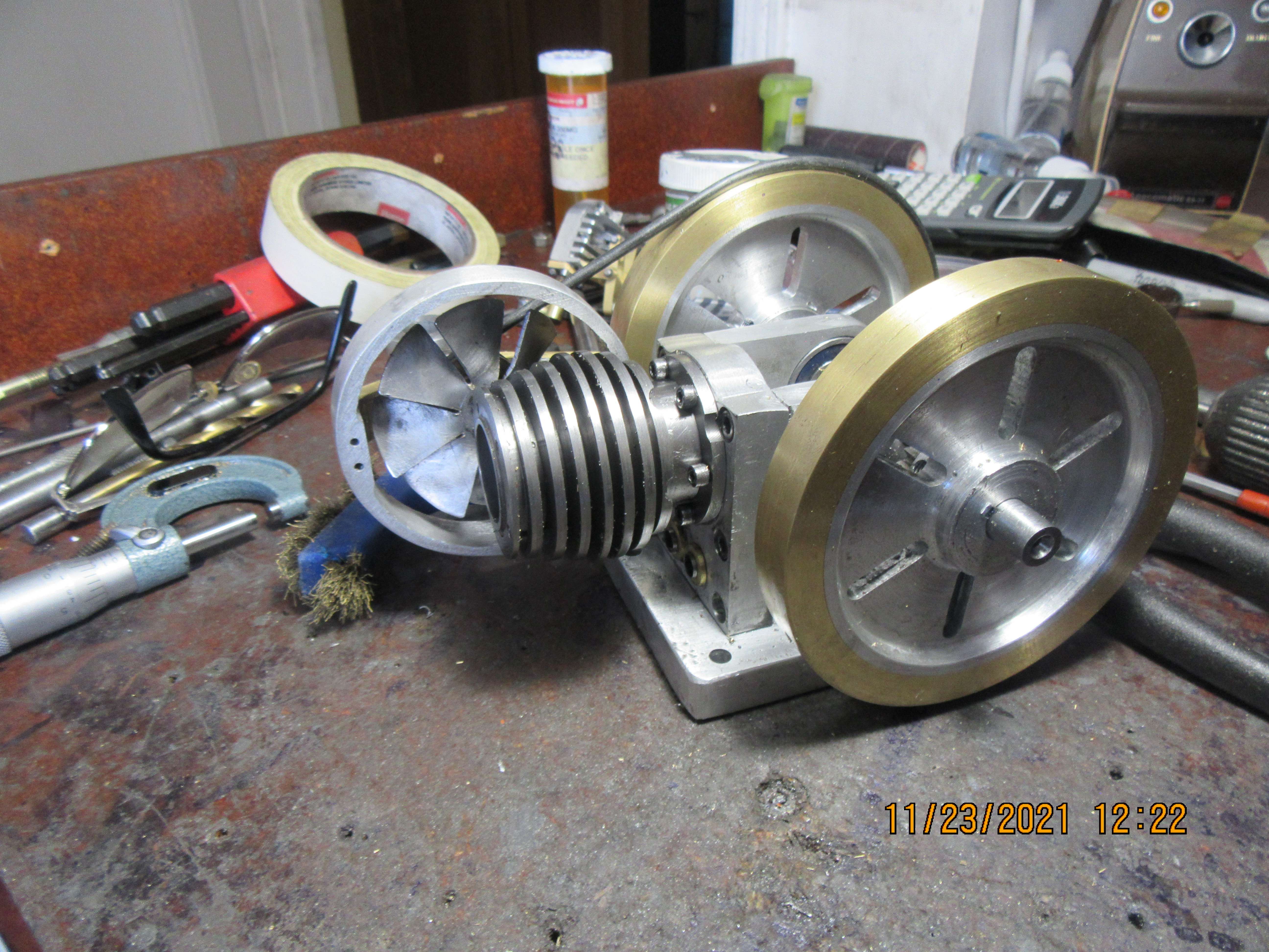
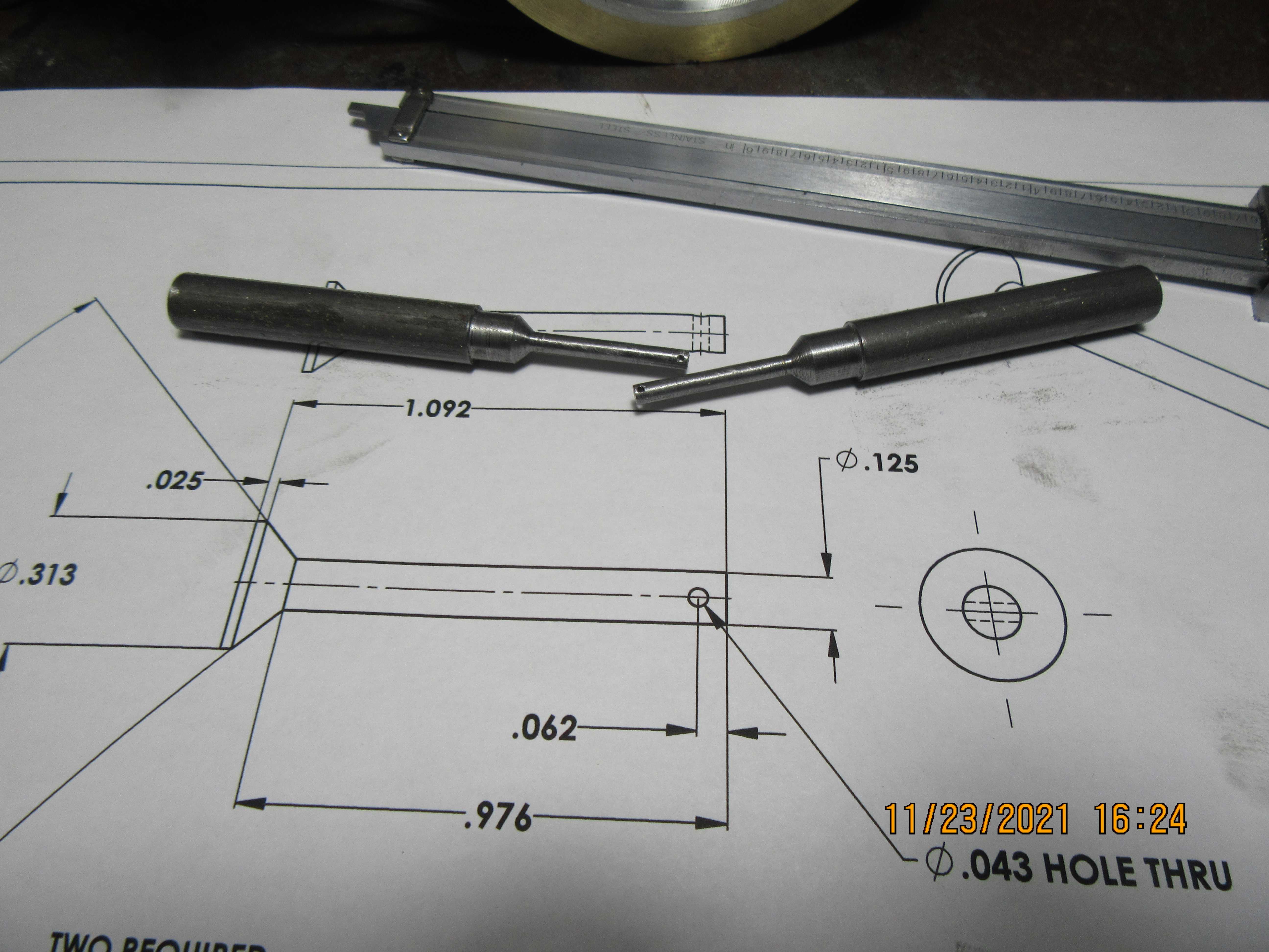
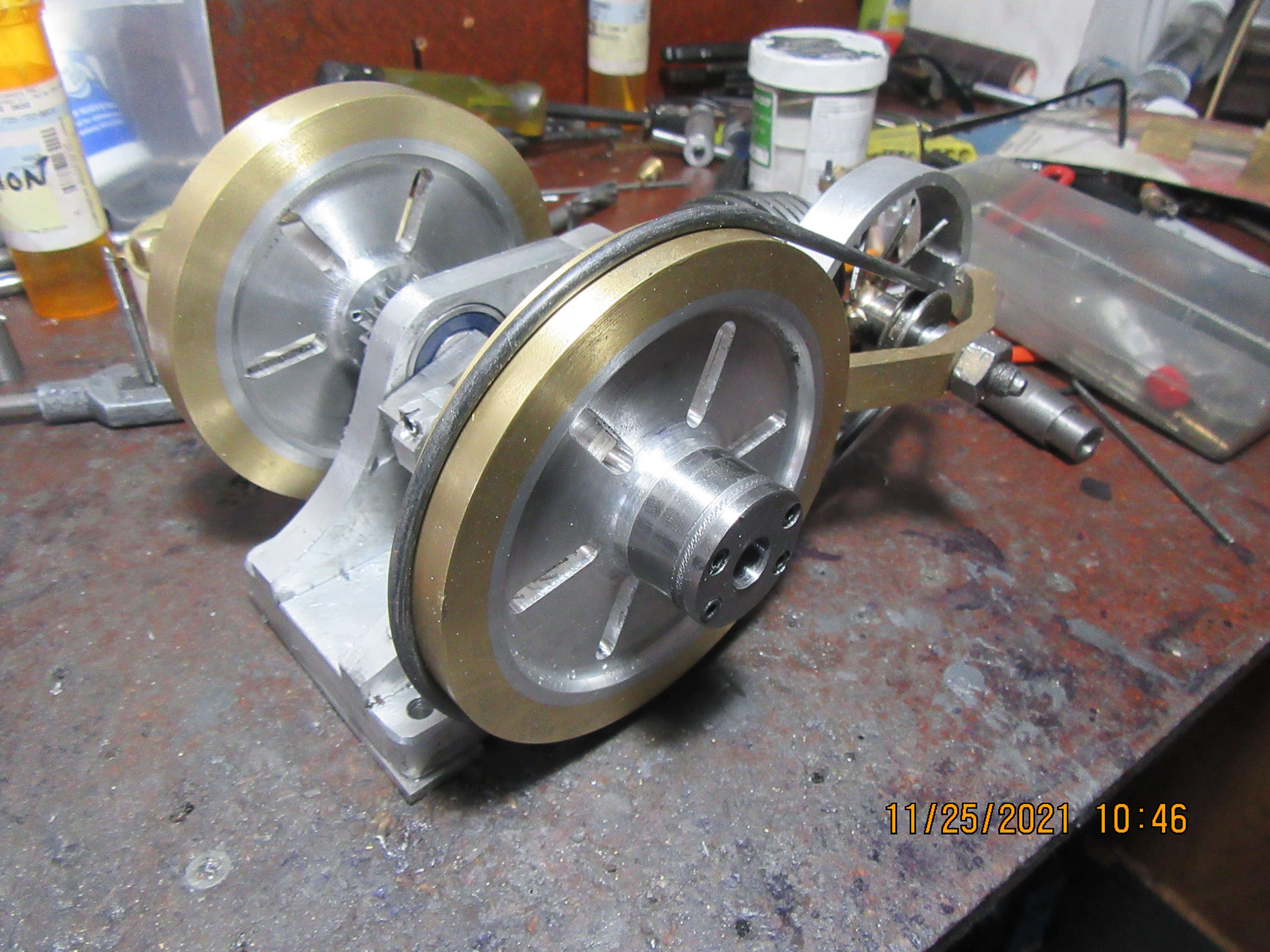
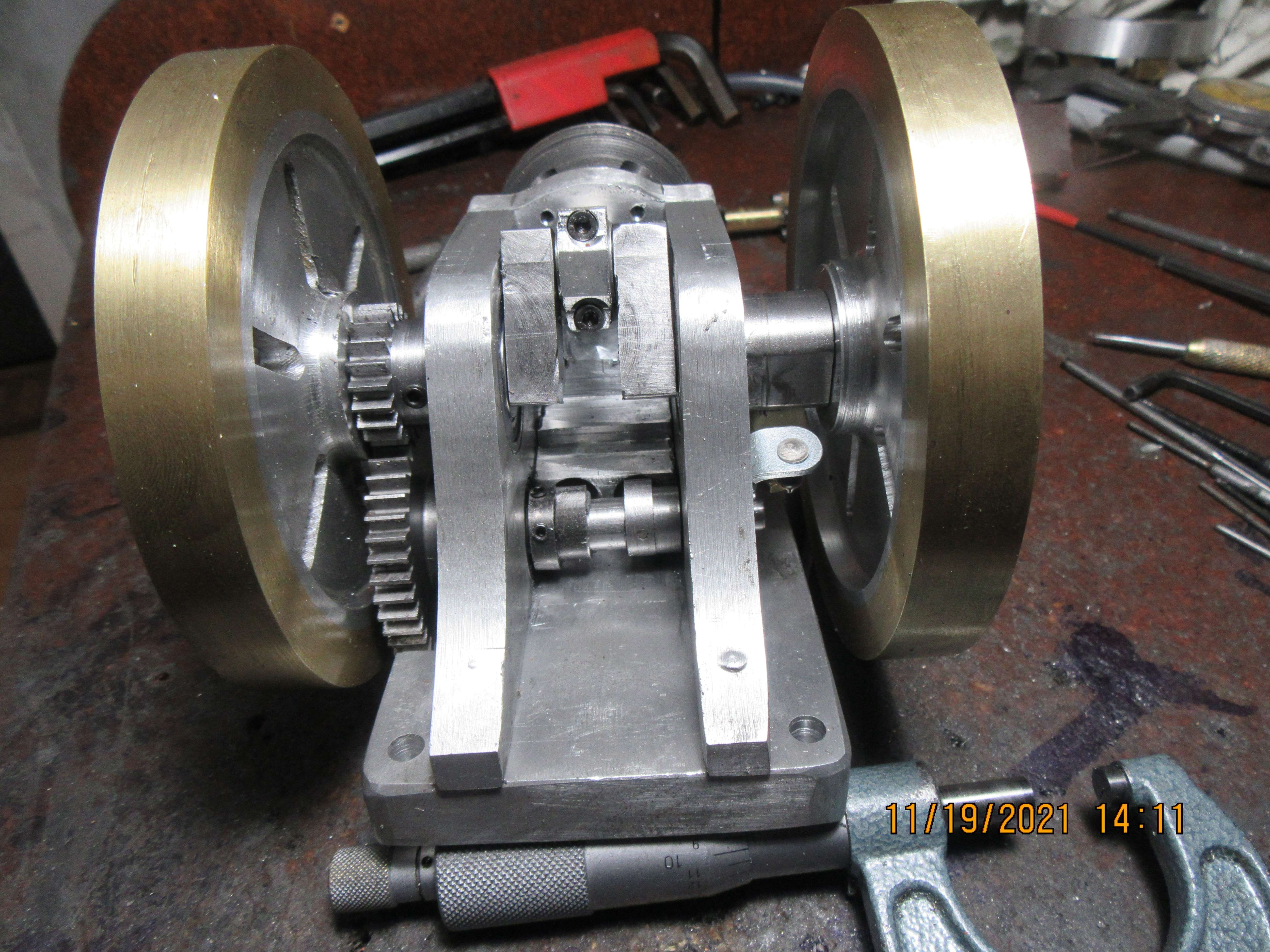
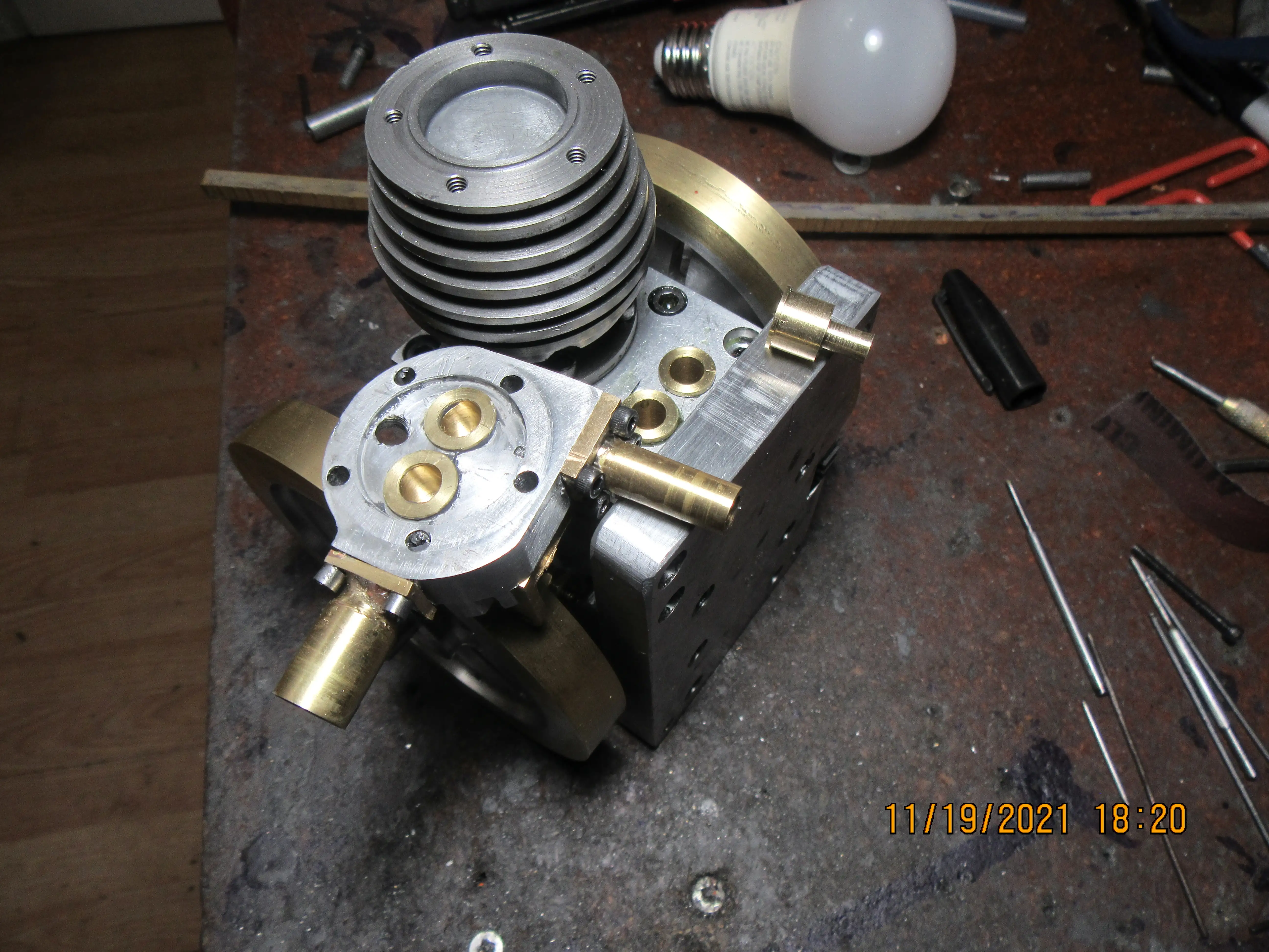
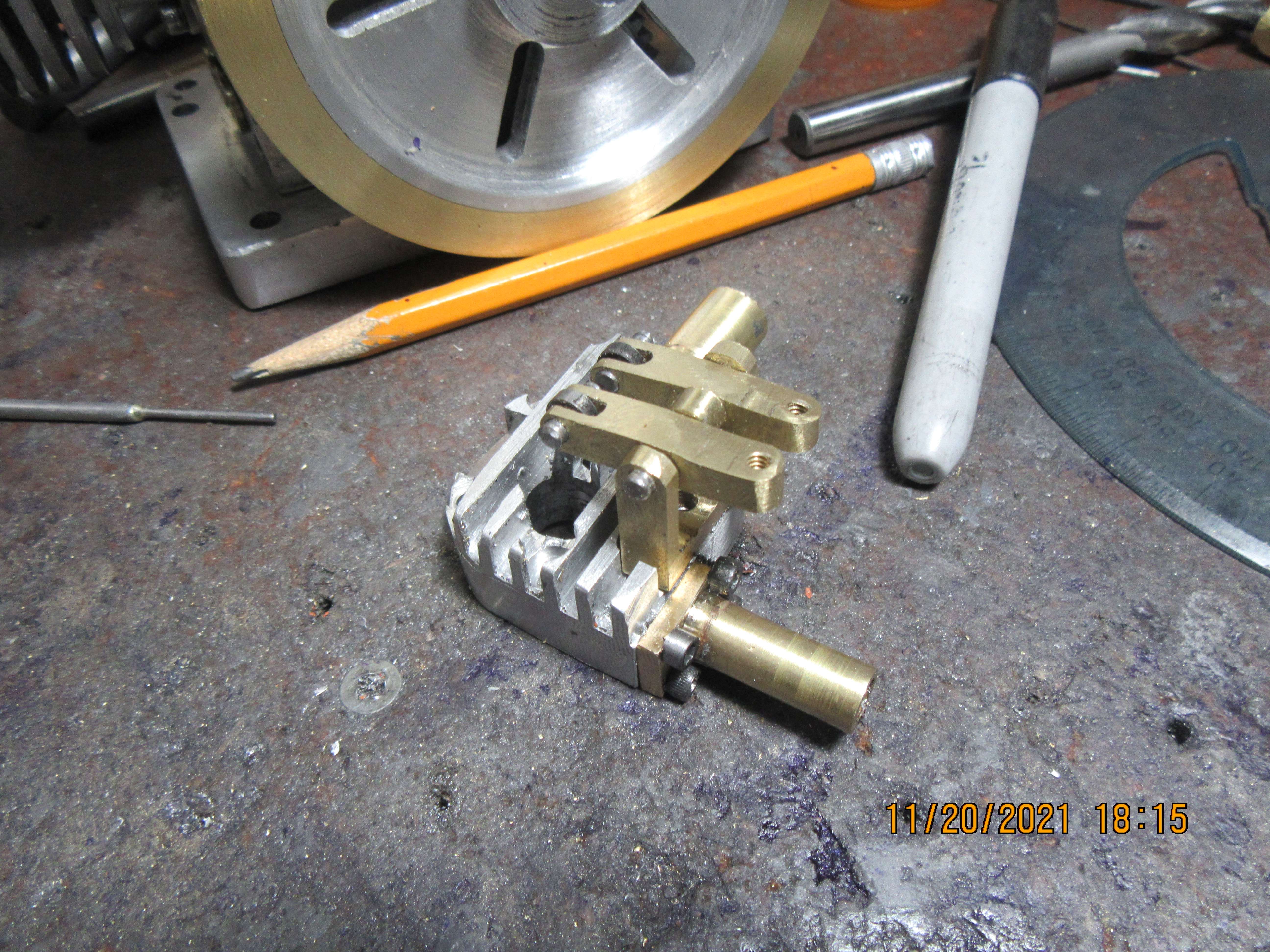
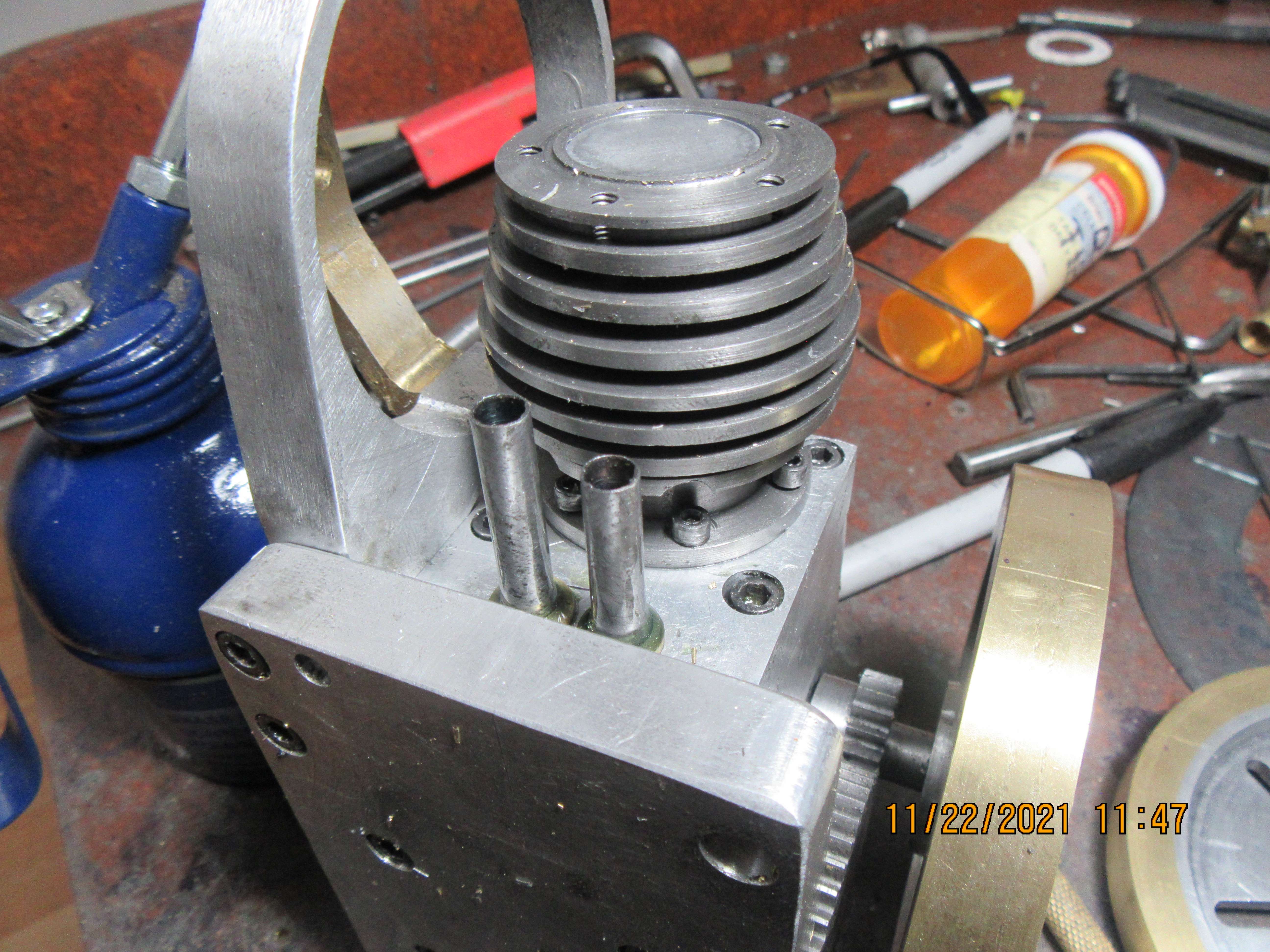
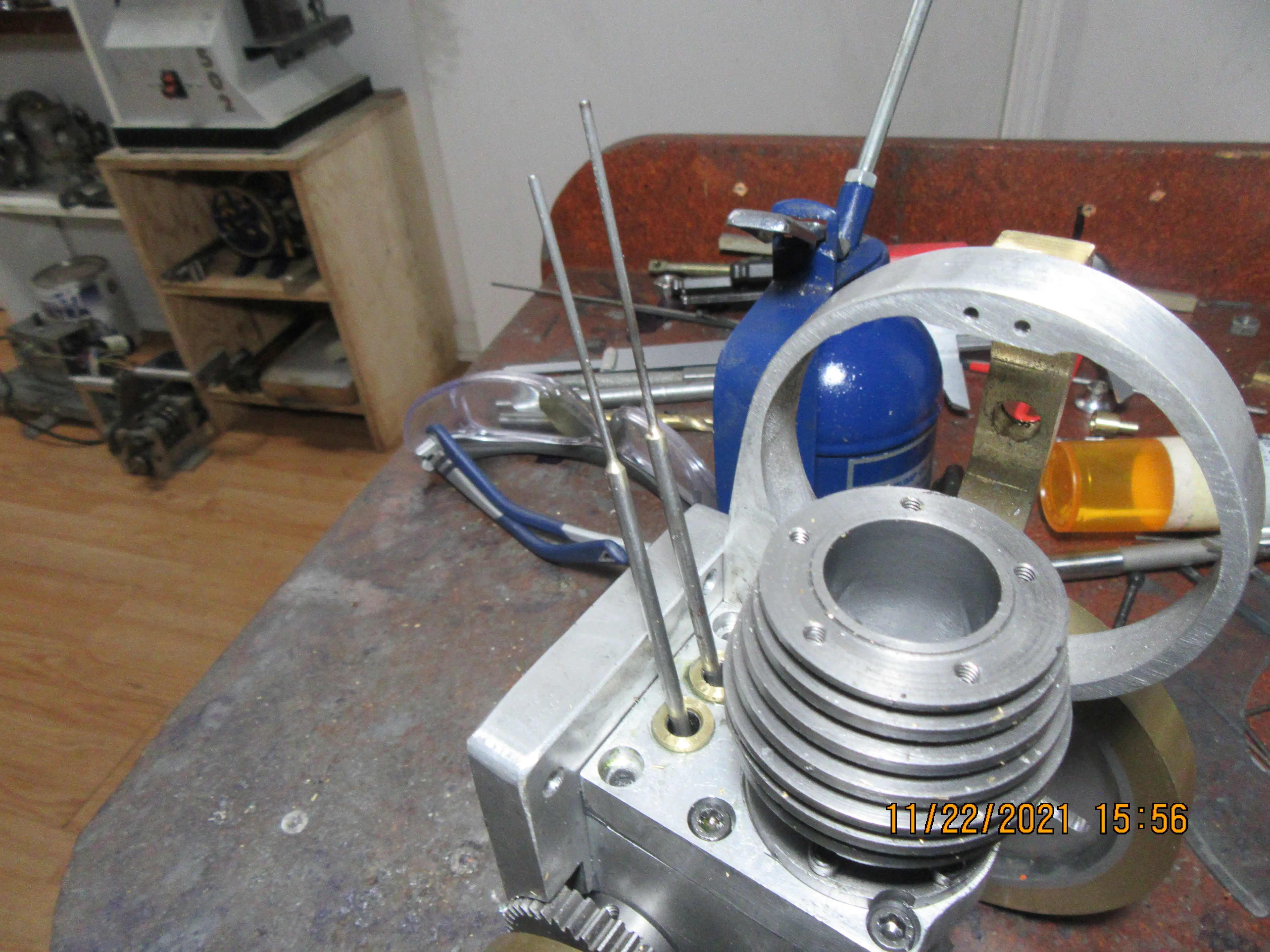
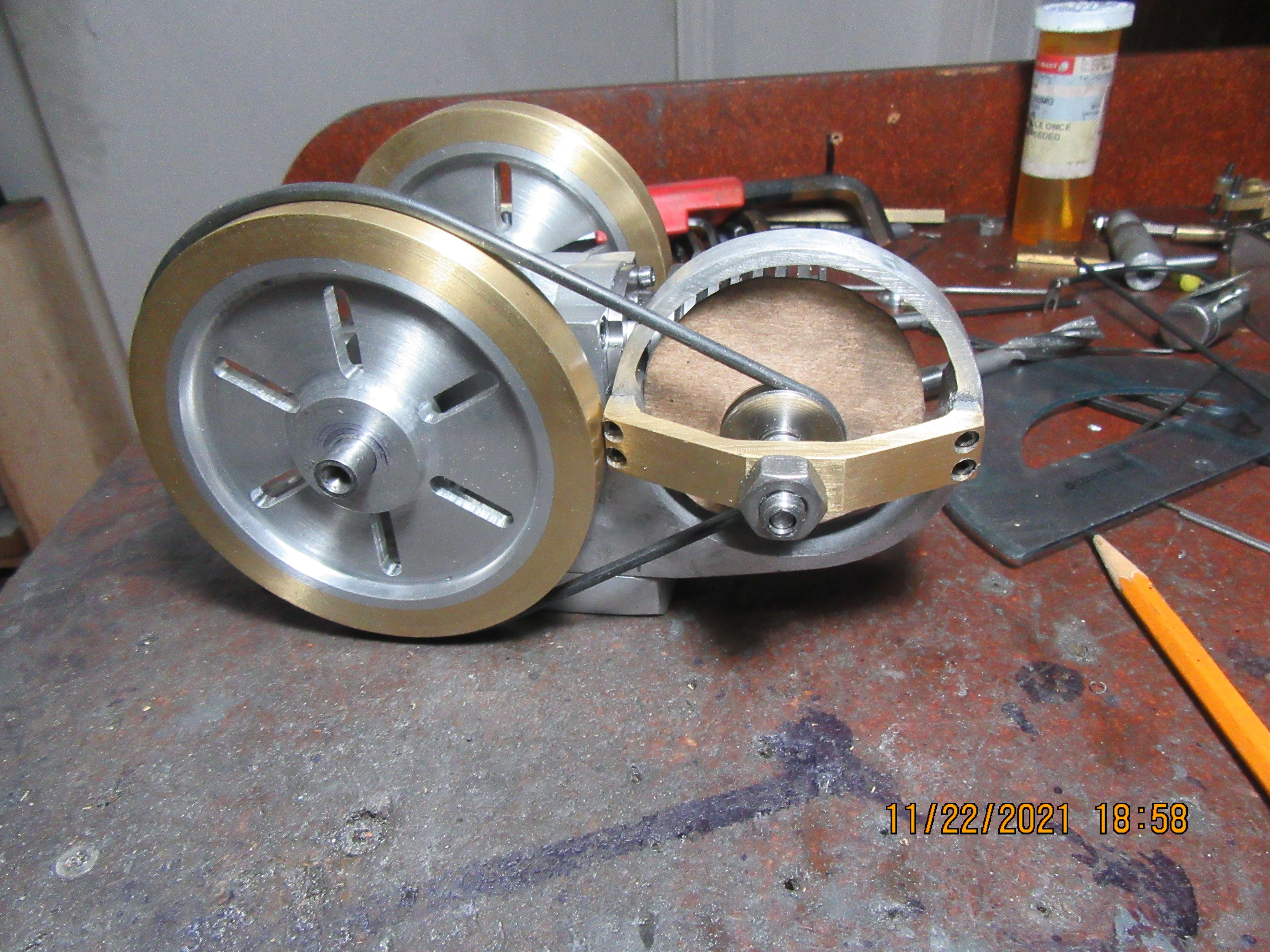
No real work accomplished today, other than mounting the cams where they will go on the camshaft and taking a picture of it with one sideplate removed. I have to pick up some 1/2" diameter brass tomorrow to make valve cages and tappet guides from, and a piece of 1/16" diameter drill rod to cross-pin the cam to the camshaft. The woman who runs BusyBee tools in Barrie called and told me about an old fellow in town who built "Steam engines and things" but was too old to work in his shop anymore. I called him and arranged a visit this afternoon and went to see what I might want to buy. He was a nice old fellow of 90, but was selling off all his shop toys. unfortunately, I have everything he has, only bigger and better. I did buy eight small cast steel C-clamps for $25, but that was all I bought.
4SJWdA.jpg
 
This morning I went down street and bought my ignition points and condenser. I machined an ignition cam and fitted it in between the sideplate and the flywheel on the side opposite from the timing gears. I flame hardened and quenched my cams in oil, and after clean up got them mounted on the camshaft. The con rod clears the cams when it rotates, by about a gnats hair. (That's about .001"-.003").
ICYNzS.jpg

MP8joj.jpg

tuoL60.jpg
 
And at the closing of the day---I have tappet guide bushings made and installed, and valve cages made and installed. Setting out by itself on the end of the engine baseplate, is one lonely valve cage that ended up being too short. I thought it looked too short when I made it (it was the first one) and after doing some checking I found that I had modelled it too short. Ahh poop!!!--Thats why, when you buy a set of drawings from me, the mistakes have already been found and corrected. My original plan was to make the rocker arms out of steel, but I found an offcut of brass that might work for me. I'll figure that one out tomorrow.
T1QOES.jpg
 
One step forward, two steps back. I realized after loctiting the valve cages into the cylinder head that I hadn't put the counterbores in the cylinder head for the valve cage flanges to fit down into. I don't have a great deal of free room in the combustion chamber, so it's pretty important that the flange sets down into a counterbore. Sparky asked me about that, and I thought about it to the point where I pulled the valve cages out of the cylinder head before the Loctite had a chance to set up. What I really need is a 13/32" diameter reamer with no chamfer on the end, with the end drilled and tapped for a pilot. If I put a counterbore in, I have to do the main hole and the counterbore all in one set-up, otherwise I can never get the counterbore concentric with the main hole. After doing some frantic Googling, I find that there are reamers with pilots available, but the reamers all have a chamfer on the end. I need a reamer with no chamfer on the end and with the end drilled and tapped so I can put different size pilots on it. Does anyone know of a commercial source for such a thing? I do have a guy near Barrie who sharpens endmills and drills and can make a custom cutter for me, but he's not cheap.---Brian
 
One step forward, two steps back. I realized after loctiting the valve cages into the cylinder head that I hadn't put the counterbores in the cylinder head for the valve cage flanges to fit down into. I don't have a great deal of free room in the combustion chamber, so it's pretty important that the flange sets down into a counterbore. Sparky asked me about that, and I thought about it to the point where I pulled the valve cages out of the cylinder head before the Loctite had a chance to set up. What I really need is a 13/32" diameter reamer with no chamfer on the end, with the end drilled and tapped for a pilot. If I put a counterbore in, I have to do the main hole and the counterbore all in one set-up, otherwise I can never get the counterbore concentric with the main hole. After doing some frantic Googling, I find that there are reamers with pilots available, but the reamers all have a chamfer on the end. I need a reamer with no chamfer on the end and with the end drilled and tapped so I can put different size pilots on it. Does anyone know of a commercial source for such a thing? I do have a guy near Barrie who sharpens endmills and drills and can make a custom cutter for me, but he's not cheap.---Brian
Why not just make your own from drill rod. I have made counterbores for cap screws. It is the same process as making the valve seat tool.

http://www.deansphotographica.com/machining/projects/mill/cbore/cbore.html
 
Last edited:
Gordon--Thank you. That is a great article. Yesterday I was chasing all over the internet trying to find what I wanted but had no luck.---I was calling it the wrong thing!!! This morning I woke up realizing that I should have been searching for a "piloted counterbore". Ran downstairs and checked the internet again and found out that everybody and their dog is selling "piloted counterbores"!!! I started phoning around and then realized that this is Saturday and all the shops are closed. This is a tool I could make but would rather buy. ---Will find out more on Monday.---Brian
 
You obviously are a better man than I am. I would have a problem with waiting for two days and then waiting for shipping. I would be in the shop making one. Making your own allows whatever size you want and it would probably not even have to be heat treated for only two cuts but I would do so if I thought that I would ever need it again
 
Probably a bit late to respond to previous posts, but I made a successful counterbore out of a broken drill of the required size. I ground the end flat first, then ground some relief on the cutting edges. I already had a pilot hole, so I started the counterbore recess with a regular drill to make sure the counterbore ran true, then drilled the remainder with the counterbore to the required depth. Worked a treat. It didn't need to be a high precision job but when I screwed the capscrews in the clearance around the perimeter seemed pretty consistent.
 
  • Like
Reactions: MRA
These two little guys that look like tubes are actually the tappets. They have a short counterbore in the end you can see and are solid at the other end where they rub against the cams. The counterbore which is about 0.350" deep holds the end of the pushrods for the valves. The cams have been flame hardened and quenched, and the tappets have also been flame hardened and quenched. They are made from 01 steel and quenched in old motor oil. Once the engine is fully assembled, you won't see these tappets anymore, as they are mostly contained in the tappet guides.
28RJoX.jpg
 
At this point, I don't know exactly how long the pushrods are going to be. I can get a length from my 3D model, but in situations like this I just make the pushrods 1/2" longer than what the computer said and will trim them to length on finished assembly.
wHN3Af.jpg
 
This afternoon I finished all of the fan mechanical parts except the fan blade. The fan is represented by the disc of cardboard, 2 1/4" diameter.---I don't know why it isn't centered in the shroud, but I can move the hole in that brass strap enough to center the fan, and nobody'll know. There is a lot going on in that fan hub. There are two 3/16" diameter ball bearings in there that were originally intended for a router, and a spacer between them.---I like it.
5yKxqG.jpg

2V8kSh.jpg
 
Last edited:
I don't know why it isn't centered in the shroud, but I can move the hole in that brass strap enough to center the fan, and nobody'll know.

Making a crude measurement in a drawing program, it looks like that hole isn't centered in the brass strap. The left side of the nut is over air while the right side is on the brass with room to spare.

Move it to the right about half the diameter of that threaded part and it centers the fan?
 
Making a crude measurement in a drawing program, it looks like that hole isn't centered in the brass strap. The left side of the nut is over air while the right side is on the brass with room to spare.

Move it to the right about half the diameter of that threaded part and it centers the fan?
Been there, done that, sucks when you read your own drawing wrong! ;)
 
This morning I cut keyways in both flywheels and the crankshaft. I fabricated a fan, silver soldered it to the fan hub, and installed the fan and hub in the fan housing. (It is now centered in the housing). We got about 8" of new snow last night in Barrie.
56jwHU.jpg

lHZQ9W.jpg
 
And I think this is it!! I machined the valves this afternoon and I don't think there is anything left to machine. I'm waiting for a piloted counterbore to come in from my supplier so I can finish up the valve cage counterbores in the cylinder head. I have to build some kind of starter hub, and maybe some kind of take-off pulley to attach to the offside flywheel. I have left the "handles" on the valves so I have something to grip when I lap the valve faces into the valve cages.---and oh Yes---I have to make rings.---Cast iron rings.
heYtH2.jpg
 
Today was not one of my stellar days. I machined the drive hub and the power take off pulley, and they turned out well. They are held onto the flywheels by four #4-40 socket head capscrews. Drilling the four holes in the starter side flywheel went well. Tapping the first flywheel hole went well. Tapping the second hole didn't. I broke the tap off flush with the surface of the flywheel. After repeated tries to get the broken tap out, I went across town to my tool shop and bought two new taps, two new drills and two 1/16" diameter center cutting carbide endmills. On arriving home, I discovered that my newest Diana Gabbeldon book had arrived, so I made an executive decision to read for the rest of the day. Something of interest--that #4 hand tap and it's drill are about 13 years old, and gets used fairly often. I measured the drill, and it measures at 0.088" diameter. the man who sold me the new taps and drills said that the standard tap drill for a #4-40 bolt is 0.094" diameter.---Who knew--
 
Today was not one of my stellar days. I machined the drive hub and the power take off pulley, and they turned out well. They are held onto the flywheels by four #4-40 socket head capscrews. Drilling the four holes in the starter side flywheel went well. Tapping the first flywheel hole went well. Tapping the second hole didn't. I broke the tap off flush with the surface of the flywheel. After repeated tries to get the broken tap out, I went across town to my tool shop and bought two new taps, two new drills and two 1/16" diameter center cutting carbide endmills. On arriving home, I discovered that my newest Diana Gabbeldon book had arrived, so I made an executive decision to read for the rest of the day. Something of interest--that #4 hand tap and it's drill are about 13 years old, and gets used fairly often. I measured the drill, and it measures at 0.088" diameter. the man who sold me the new taps and drills said that the standard tap drill for a #4-40 bolt is 0.094" diameter.---Who knew--
Don't know where he got that dimension, if you use the nominal size - the pitch the tap drill should be 0.087 and a #43 drill which is 0.002 oversize will produce a 70% thread. IF a 3/32 drill, drills on size it will produce a 56% thread which really isn't 'standard' though if you're going more than 6 or 7 threads deep in anything but aluminum you won't loose a large amount of holding force.
 
Once again the old and arthritic have defeated the powers of darkness. It cost me a 13 year old #4-40 tap and a new 1/16" carbide endmill, but in the end the broken tap was removed and the hole was rethreaded at the correct size. (on #4 taps, that trick actually works about one time out of three for me.) So, the engine now has a starter hub on one side and a power take-off pulley on the other.
0kgKd5.jpg

ztqkh4.jpg
 

Latest posts

Back
Top