Horizontal Air Cooled Engine

Home Model Engine Machinist Forum

Help Support Home Model Engine Machinist Forum:

This site may earn a commission from merchant affiliate links, including eBay, Amazon, and others.
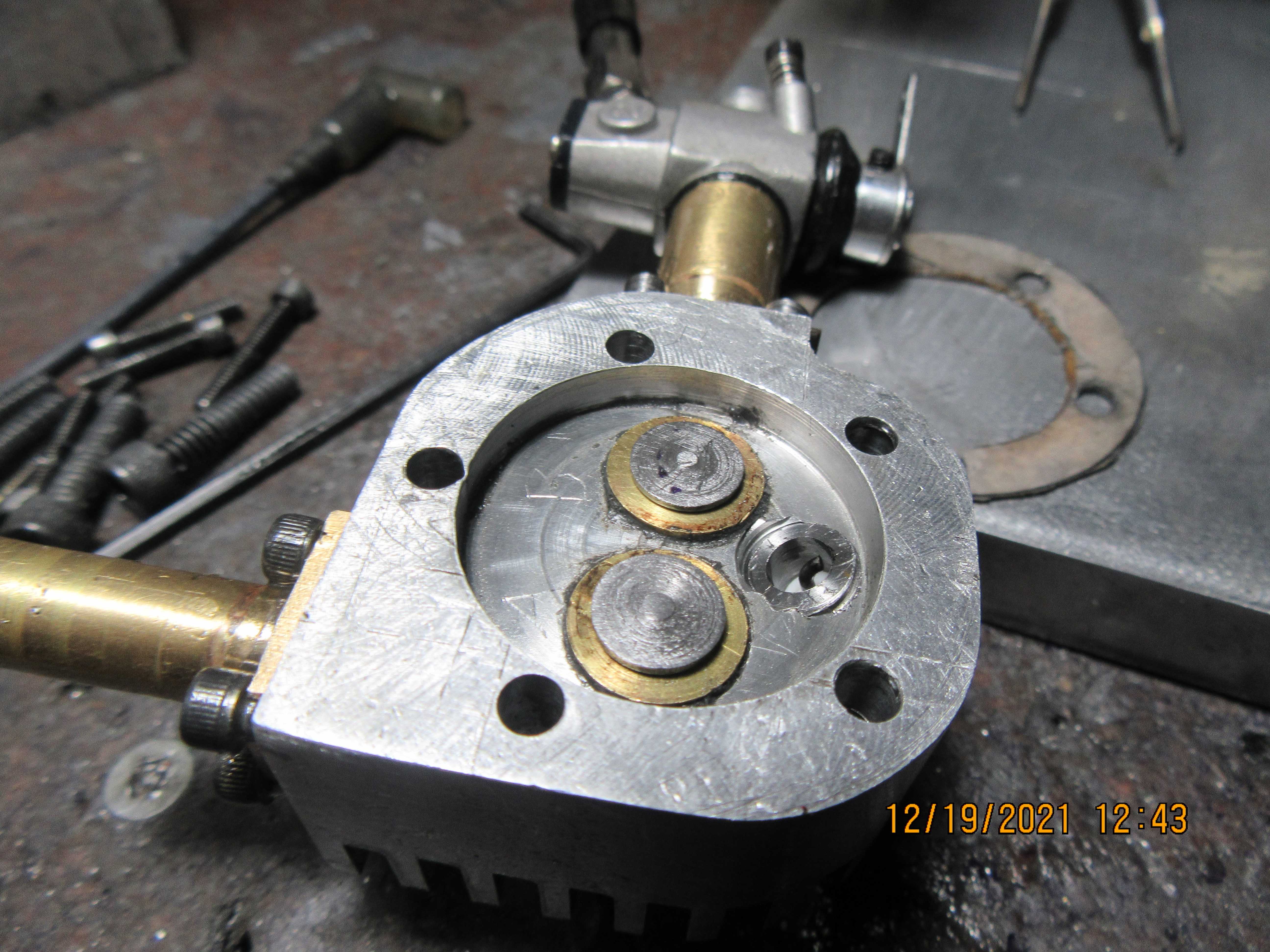
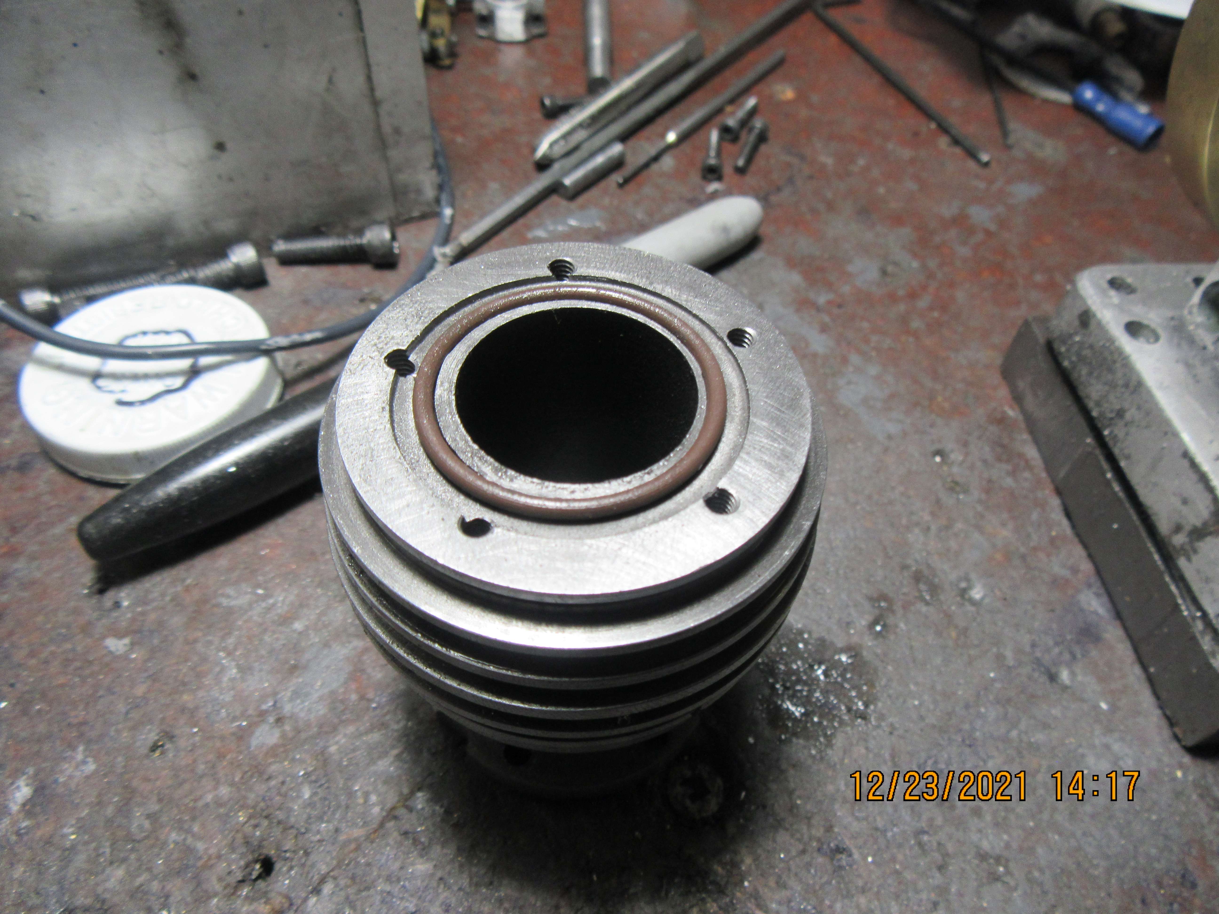
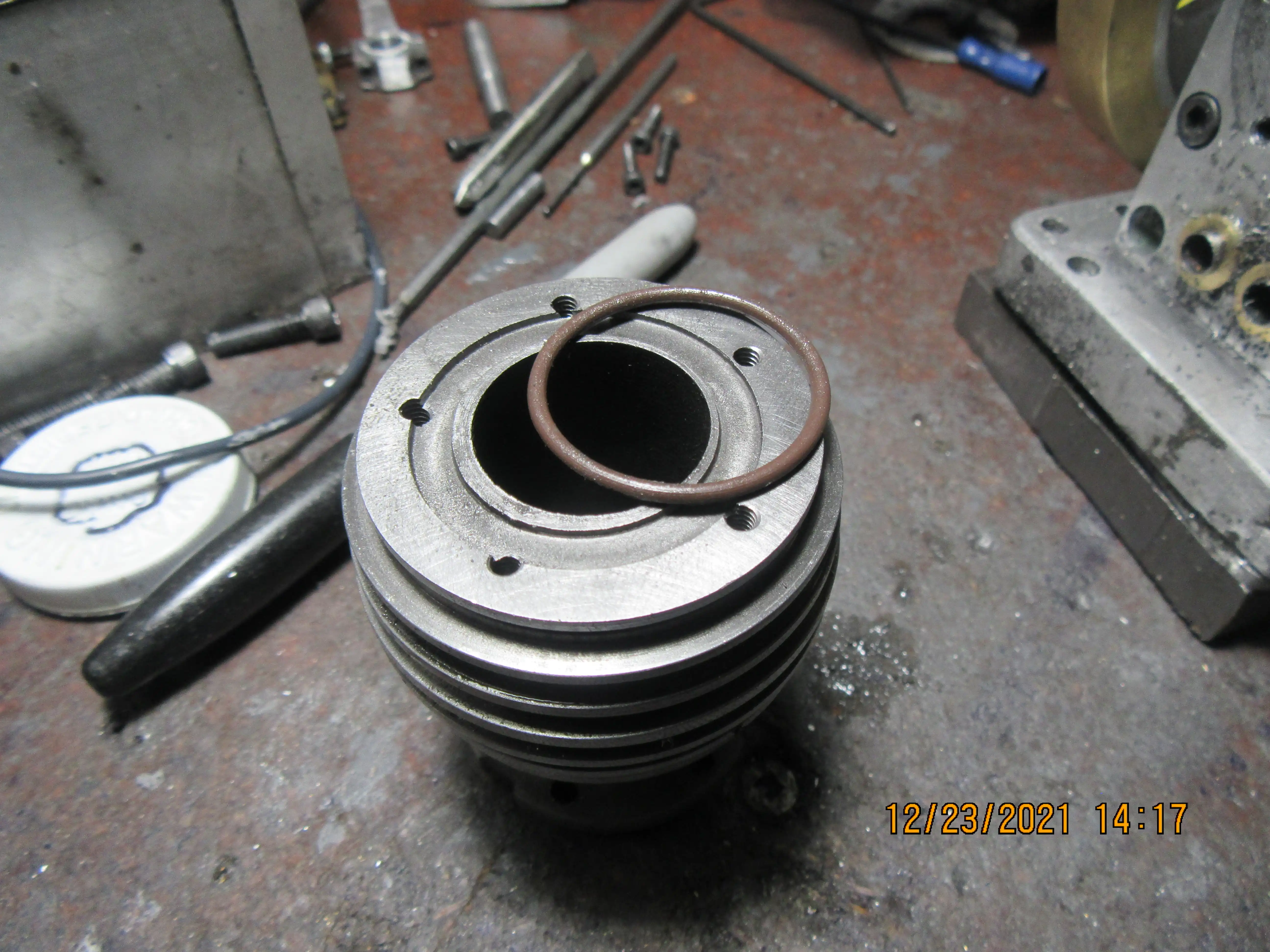
Okay---Just pulled the head off. This is a view of the inside of the cylinder head. There was nothing funky about the head gasket. There was nothing funky about the position of the sparkplug relative to the valves. The only thing I can see is that the spark from the center electrode to the side of the plug is happening on the side away from the valves. If I put a small brass washer between the sparkplug and the cylinder head, I hope to be able to re-tighten the sparkplug and have it so that the spark jumps to the valve side of the sparkplug. It seems highly improbable that this would cause a "no fire" situation, but when everything else has been checked, we start to seek out the improbable and correct it.
aXrIaU.jpg
Actually, your conjecture does not sound all that improbable at all. Can you make a washer that is the thickness of half a thread? That would turn that plug around half a turn.
 
YES!!!!--That did it. Engine is now finally firing. Turning the sparkplug 180 degrees so that the spark was occurring closest to the valves done the trick.---I'm happy--happy--happy. Next amazing stunt will be getting an extended run and making a video.
Hi Brian, Clever you! - for deducing the spark location has an influence on running! - I would have reduced the spark gap by a few thou... as sometimes that enables a good spark to be obtained when the spark is otherwise too weak (strung-out) to fire the mixture.
In HV circuit breakers (a part of my life's apprenticeship), the intent is to "extend the arc" so it can be "blown-out" (I.E. cooled, so the ionisation fails within the electic field strength), as short fat arcs take a lot more puff to extinguish! (A near spherical zone of ionised gas is much hotter and a better conductor than a long narrow "cylinder" of ionised gas). As an ignition source, the spark between the contacts of the spark plug is intended to be "near spherical", not long and drawn-out, with some "turbulent flow" of the fuel gas between the electrodes. The ionisation voltage at the electrodes ionises and heats the fuel molecules and air molecules, so that they combine and exothermally release their chemical energy to initiate the combustion... The field strength between the electrodes has to be high enough to strip electrons from the fuel and O2 molecules in order to do this. A gap that is "too large" will not have the field strength required, but a shorted gap will, for the same voltage. (A Champion Spark-plug designer taught me the details - which I have mostly forgotten - so this explanation may be imperfect!).
All good Engineering!
Well done Sir!
K2
 
And since we last spoke---things have went off the rails. I had reached a point in my trouble shooting where I had discovered that the engine WOULD fire if I rotated the sparkplug 180 degrees to bring the spark closer to the valves. And immediately after I discovered that it would fire, I started loosing head gaskets. Multiple fixes were tried, but sadly there was no good way to fix it. Ultimately, I have decided to make a new cylinder and cylinder head. And yes, we're going to try something different. All of my previous i.c. engines have worked just fine using head gaskets made of 0.031" thick general purpose water pump gasket material. Now we're going to go away from conventional head gaskets and try our luck with a Viton o-ring head gasket. The two highlighted areas in this model indicate where the o-ring is going to go. These 1/16" o-rings actually measure 0.070" in cross section. The annular groove will be plunge cut with an 0.094" wide cut-off tool and will be cut 0.018" deep in both the cylinder and the cylinder head. This will give me 0.034" of "squeeze" when the head is bolted to the cylinder. The fact that the groove is 0.094" wide will give the o-ring material somewhere to be displaced into when the head is fully tightened down on the cylinder. A day will make me a new cylinder, and the new cylinder design will leave more clearance between the base flange and the first "cooling fin" (I had a horrible time getting the bolts in that hold the cylinder to the vertical plate). There won't be much visual difference in the new design, except the top ring on the cylinder will be slightly larger in diameter, as will the head. I can probably make a new cylinder head in a day, but with Christmas it will probably be more like two days.
LhjqTN.jpg
 
Last edited:
That means that you can go back to your original spark plug too.
 
I ditto what Terry has stated. You'll probably strip the bolts before you get the head fastened down.
You'll want the head to fasten down until it touches the cylinder to get heat transfer.
10% of the material diameter (.07 x .1 = .007) squish would be plenty for a seal and even that much for a ring that diameter might be too much to compress easily.
As suggested, have a look at some charts on an O-ring manufacturer website for that usage case.
 
Hi Brian, back in my early days as a Motor mechanic 50s 9I'm an old geezer). A make of English car with poorly designed cylinder head bolt spacing, they blew head gaskets frequently.
We removed the head and replaced the gasket but before installing same we painted the gasket both side with silver paint and never had one blow after that. Why not give that a try on your original head and cylinder. I would get some 5 thou thick copper shim and make a gasket out of that, some silver paint and I would be very surprised if that would leak. I personally do not use gaskets on small engines just some gasket cement (shellac)
 
YES!!!!--That did it. Engine is now finally firing. Turning the sparkplug 180 degrees so that the spark was occurring closest to the valves done the trick.---I'm happy--happy--happy. Next amazing stunt will be getting an extended run and making a video.
Are you sure it was really a rotation of the plug gap? The brass washer might actually have sealed a leak between the plug and the head. If combustion really is sensitive to the rotation of the plug gap, that might be caused by the valve seats sitting so high in the combustion chamber. Also it looks like your head bolts are too close to the edge of the combustion chamber for a viable head gasket. One threaded hole looks like it may even have broken through. You may be leaking into the head bolts. If you haven't actually measured leak down or compression, the no-start problem may be due to a basic lack of sufficient compression. - Terry
 
Could you not have just redone the head as it was originally drawn with the shallow recess. That way like many other engines the seal is on the narrow raised "ring" around the top of the cylinder or liner not the flat area beyond with the risk of pressure escaping up the screw holes as on yours now there is no seal from combustion chamber to these holes.

You don't even need a gasket with the head sealing against the narrow "ring" at least mine run that way, I think Keep it Simple is what they say.
 
Hi Brian, back in my early days as a Motor mechanic 50s 9I'm an old geezer). A make of English car with poorly designed cylinder head bolt spacing, they blew head gaskets frequently.
We removed the head and replaced the gasket but before installing same we painted the gasket both side with silver paint and never had one blow after that. Why not give that a try on your original head and cylinder. I would get some 5 thou thick copper shim and make a gasket out of that, some silver paint and I would be very surprised if that would leak. I personally do not use gaskets on small engines just some gasket cement (shellac)

you can also pick up copper head gasket spray. i use it on the non coated metal head gaskets on farmall super a and cultivision a tractors, else they leak every time. but spray both sides of the gasket with that copper spray and let it "tack" up a bit then drop it on and bolt the head down and 0 leaks. i get it at Napa Auto parts

1640182588583.png
 
So, here we go. Out with the old cylinder and in with the new cylinder. You will notice that the new cylinder has a much wider "land" at the cylinder head end. This is to allow for the o-ring seal and so that the counterbored holes in the cylinder head don't break out past the edges of the cylinder head. You will also note that I have left much greater space between the bottom cooling fin and the mounting flange to make it easier to get that ring of bolts in place.
f8yDRC.jpg
 
The new cylinder is finished and the o-ring groove is cut into it's mating face. I probably would have liked it better if the o-ring groove had ended up concentric with the bore, but when it's all buttoned up, nobody will see that. It won't have any effect on the way the o-ring seals. That ring was machined in there with a 3/32" endmill while the cylinder was held in the chuck mounted on the rotary table. I might have ended up with a truer set-up if the cylinder had been mounted on a four jaw chuck in the lathe, but I'll remember that for next time.
40eprV.jpg

iKFxGl.jpg
 
Just asking Brian but shouldn't the width of the groove be about the same as the width of the oring? Seems like any leak in compression would force the oring to the outer diameter of the groove and possibly damage it by over stretching it. Maybe use an oring that fits the outer diameter of the groove? Am I over thinking?
 
Hi SteveH... I agree, in principle, but the friction of clamping the O-ring may be adequate to prevent the combustion pressure forcing the o-ring out - to cause a leak. Brian will find out, and probably make a backing ring to prevent this if necessary?
Perhaps another "worry" is that the increased volume (at Top-dead centre or compression at the ignition point) may well be considerably reduced by the extra volume created if the o-ring is permitted to expand so far, leaving an inner annulus of volume connected to the combustion chamber. May be a simple (if temporary?) fix would be to fill the gap outside the o-ring with Silicon Seal? - Cures to solid, remains elastomeric, manages relatively high heat, easy to clean-off afterwards, etc. - Just a thought...
K2
 
Something not right with the sizes stated, if that is a 1/16" nominal ring then it is actually 0.070" wide in which case there is no way that groove is 3/32", looks more like 5/32"❓

Hopefully if the groove in the mating head gets cut to the stated sizes that may stop the ring moving about
 
Why do you need a groove in both the cylinder and the head? It would seem like full depth groove in either the cylinder or the head would work.
 
Gordon--You are right. A full depth groove in the cylinder or in the head would do, in fact that is what o-ring book suggests. However, since the ring is sealing against compression, I think that it would work best if the groove is partially in both. I haven't done this before, so I'm aiming for 50% compression of the o-ring when both surfaces of head and cylinder touch each other with the bolts torqued down. I will let you know how this works out.----Brian
 
Okay!!!---Christmas is over. Santa did come. Second son showed up for Christmas dinner and brought his new Ojibway girlfriend. (she is a very nice girl). Everybody else stayed home and "Christmassed" with their families---Too much Covid around for big family get togethers. When I put that o-ring groove in the top of the cylinder, I grabbed the wrong size endmill.---Poop!!! It has been fixed with a steel back-up ring to fill up the extra space, and now the groove is 3/32" wide to accept the 1/16" o-ring.. Work is proceeding on the engine. New cylinder is finished. New cylinder head is 3/4 finished.
 

Latest posts

Back
Top