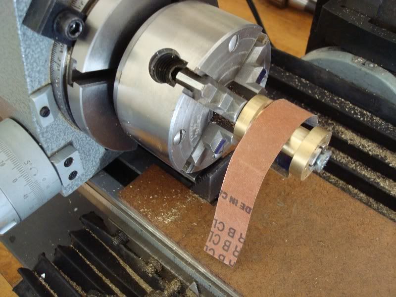
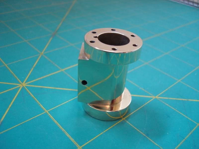
I finished milling the body of the cylinder. The last step is to round the back of the cylinder. I just purchased a 4" round table to do that job but I will have to wait a week for a #2 MT insert to mount my chuck on the table.
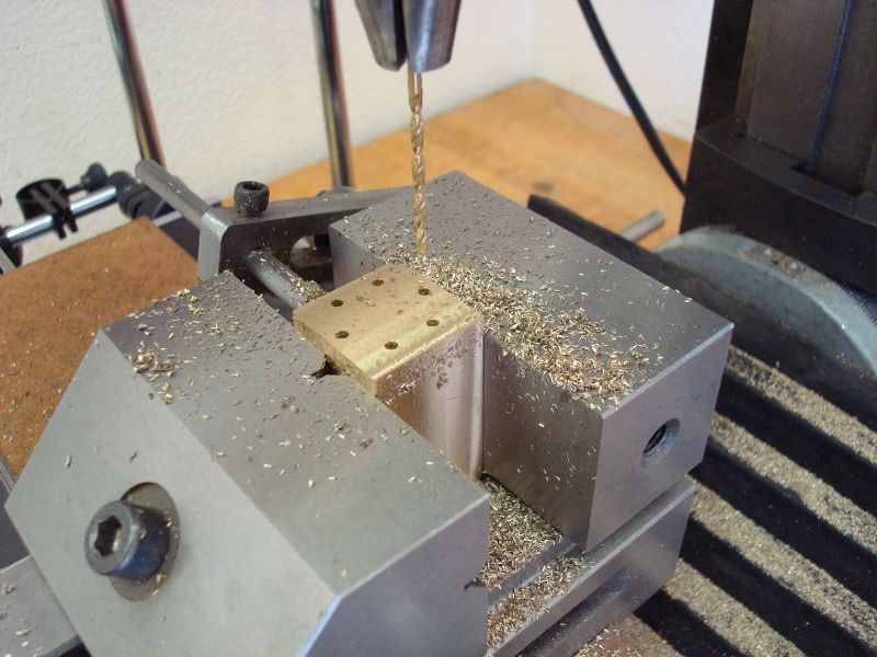
What size end mill would work the best for rounding the back side? I used a 1/2" to mill down the sides.
Ed
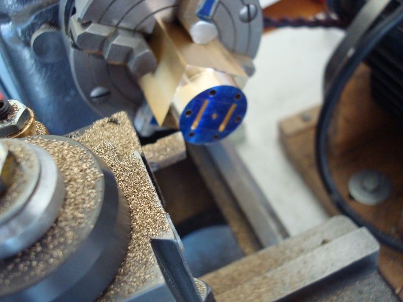
What size end mill would work the best for rounding the back side? I used a 1/2" to mill down the sides.
Ed
")