- Joined
- Feb 17, 2008
- Messages
- 2,326
- Reaction score
- 440
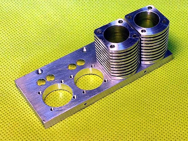
I found a bust in my CAD drawings. A stupid snap to the wrong place that then propagated to several more detail drawings. It will take a couple of hours to clean them up. I did get the cylinder heads detailed out enough that l could order material for them, which I did a few hours ago. And, as they were not affected, I made the short connecting rods.
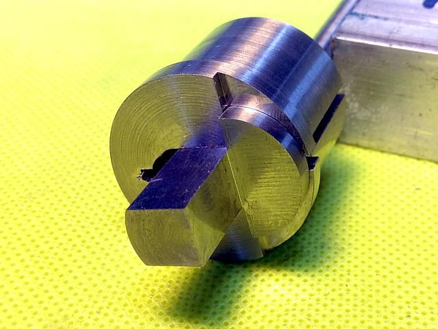
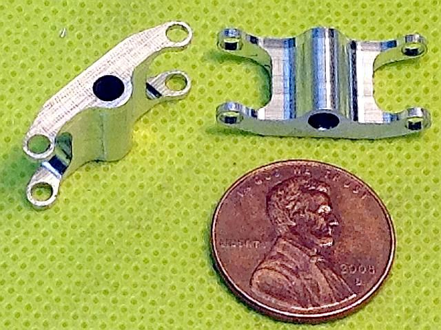
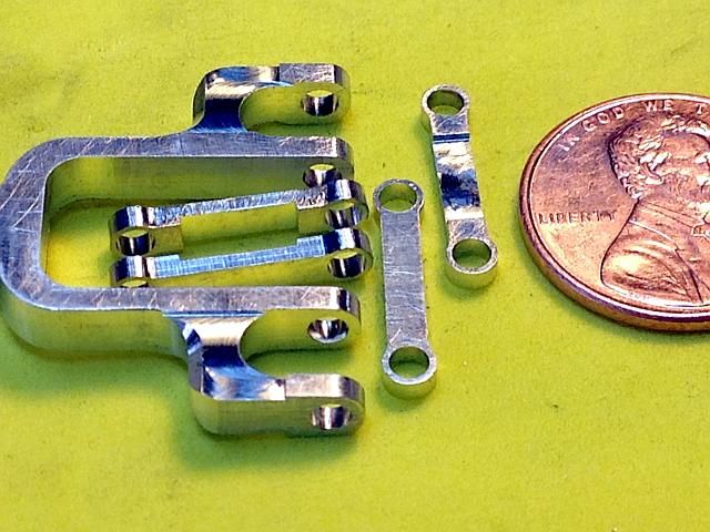
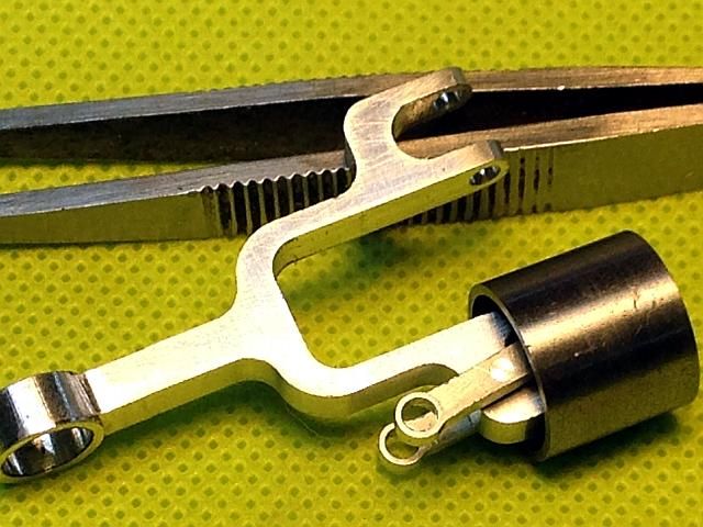
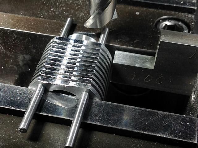
In the first photo you can see a 1/16 diameter spot in the middle each rod. This is to identify them as being made of 6061 alumninum as the final ones will be made of 7075. I only need 8 for the mock up blut of course I made extras to feed the swarf bunnies.
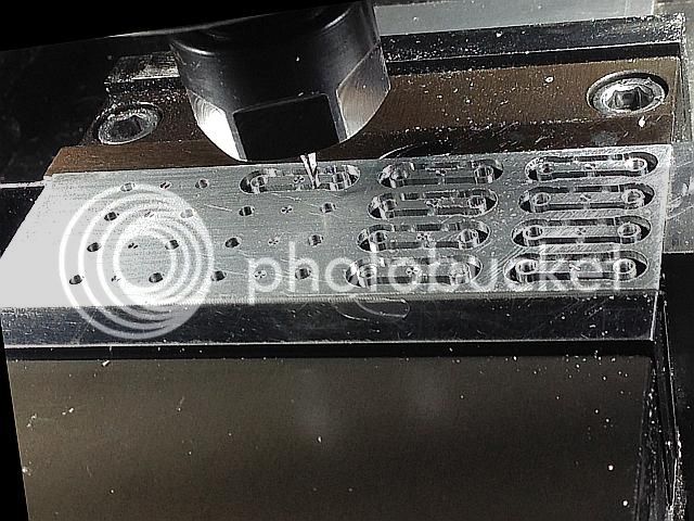
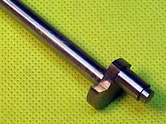
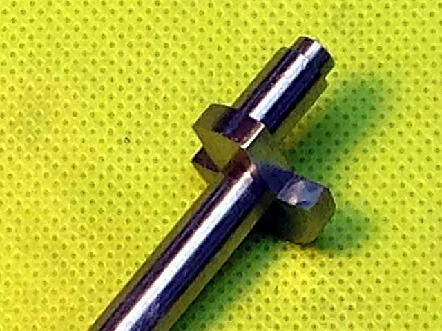
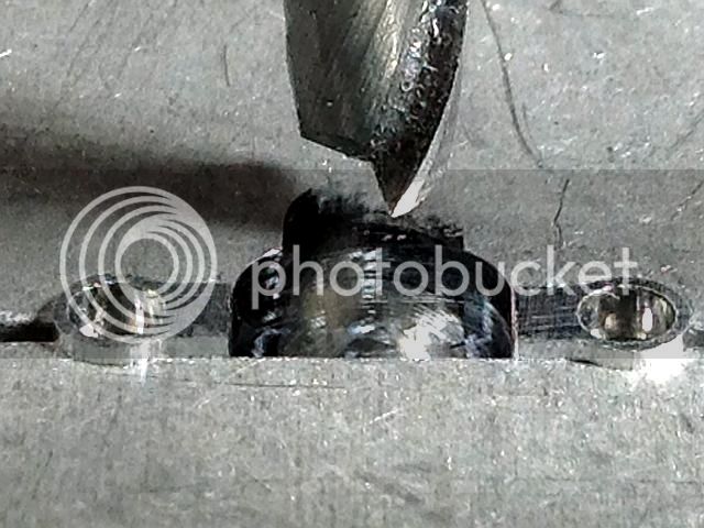
Here is the other side so you can see the three small tabs used to hold the part in place for the final finishing operations. They are 0.007 wide and 0.015 thick. You can also see that I did not all the exit burrs from reaming off the parts on the right end. They are gone now. Just have to clip the parts out with a pair of diagonal cutters and file off the bits of the tabs that are left.
Gail in NM
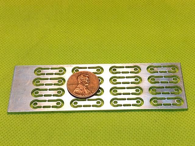
In the first photo you can see a 1/16 diameter spot in the middle each rod. This is to identify them as being made of 6061 alumninum as the final ones will be made of 7075. I only need 8 for the mock up blut of course I made extras to feed the swarf bunnies.
Here is the other side so you can see the three small tabs used to hold the part in place for the final finishing operations. They are 0.007 wide and 0.015 thick. You can also see that I did not all the exit burrs from reaming off the parts on the right end. They are gone now. Just have to clip the parts out with a pair of diagonal cutters and file off the bits of the tabs that are left.
Gail in NM
")