Dieter Hartmann-Wirthwein patent engine by Gail in NM

Home Model Engine Machinist Forum

Help Support Home Model Engine Machinist Forum:

This site may earn a commission from merchant affiliate links, including eBay, Amazon, and others.

GailInNM

Administrator
Staff member
Administrator
Global Moderator
Joined
Feb 17, 2008
Messages
2,326
Reaction score
440
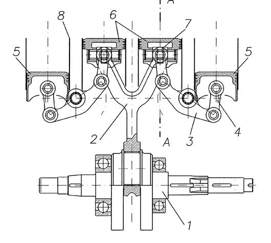
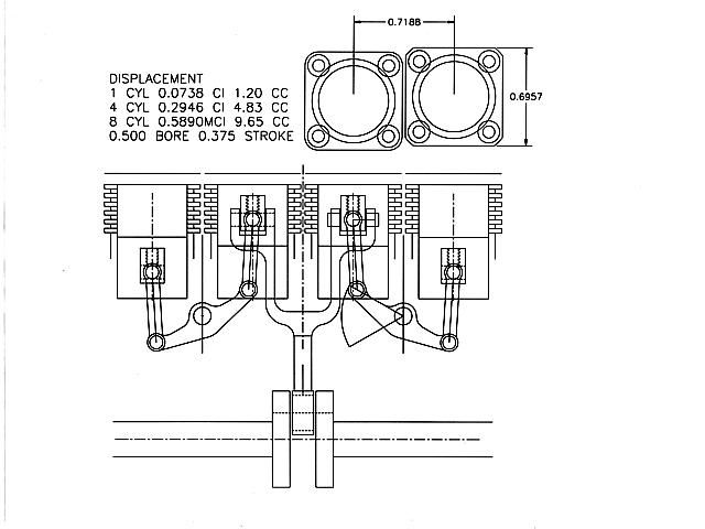
A few years ago there was a flurry of interest about the Ducati Elenore V8 motorcycle. A V8/lnline 4 patent drawing was released by the inventor of the engine. To my knowledge there were only two prototypes built. One a V8 of about 860 cc displacement and one an In-line 4 of 125 cc displacement. Both were installed in Ducati motorcycles and there are a few Youtube videos of them running. I don't know of any models being built.

I have found very little information on the engines. One page of the patent and the video model that I have attached to this post. A few general specifications and a few photos of the engines external appearance. Most everything else links back to these sources. A couple of little discussions on HMEM a few years ago went nowhere. I would welcome any additional information on these engines as I am far from being a master at searching the internet.

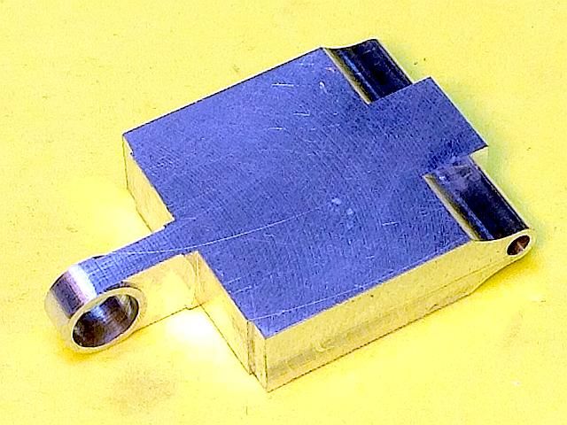
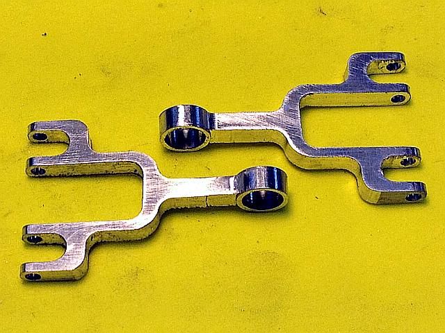
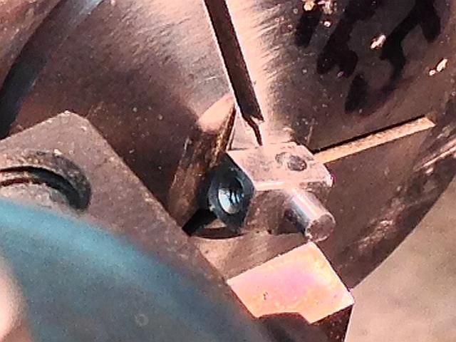
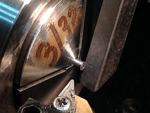
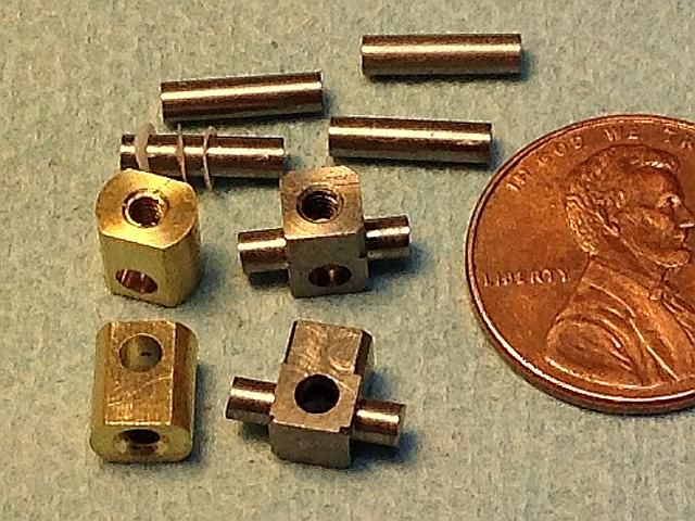
What I am thinking of doing is building a 45 degree slant 4 in line demonstration engine with an open crankcase so the motion can be seen. Design would be so everything could be mirrored and a second set of parts built that could convert it to a V8 if the inline 4 is successful. Only two parts should be troublesome. The forked main connecting rod and the piston with two intersecting orthogonal wrist pins. The wrist pins had me stumped for a while but I now think I have a way that will work. Everything else is standard design stuff.

All comments are welcome. I have not detailed out any parts yet. Just a few (bunch) of sketches.
Gail in NM

ducati-v8-drawing_zps5c092a2f.jpg


[ame]http://youtu.be/7E6KglXPmTs[/ame]
 
Last edited:
Very, very interesting engine. Sorry I don't have anything to contribute,
but I'll be looking forward to seeing your progress.

GUS
 
Thanks Gus.
A gentleman on another forum chased down the patent abstract and following that link I found the patent grant that has a fairly good description of what is going on along with a drawing of the piston.
http://www.google.com/patents/DE102008047719B4?cl=en
Gail in NM
 
Here is a sketch of things. I have started drawing things up a bit so I can build a dummy mock up of the action. l Everything is scaled for an engine with a 1/2 inch bore by 3/8 stroke. This is quite a bit over square and new territory for me. All the engines I have built in the past have had square ratios or been under square. But it is a balancing act on this engine. As the bore increases it gets harder to get the cylinders close together and have enough cooling fin area. I could make it liquid cooled but I really don't want to. If I use a small bore and larger stroke the angularity problems with the linkages increase and I run out of room inside the piston for all the goodies. This seems like a good compromise.
DeiterSketch1_zps3ffcd1d4.jpg

First up on the mock up parts will be the forked connecting rod. I need it to check clearances and I think it will be the most difficult part to make.

I will make it out of 6061 aluminum but the actual engine connecting rod will be made of 7075 T6 for the additional strength in the thin sections. The work is not lost in making the mock up parts as if it is successful I can use the fixtures to make it to make the working parts.

No shop time tomorrow so it will have to wait until the weekend. I will post photos as I go.
Gail in NM
 
Where's the pop corn. Time to sit back watch the good stuff...:):)


Pat H
 
Goodness, only Ducati could come up with something like that.
Yes, an open-view engine with all that going on inside will definitely create some interest.
Will you be building it with the traditional desmodromic valve gear as well?
 
Thanks for the support and interest.
Hopper: I originally thought that Ducati was responsible for the development of this engine but the more I look into it it seems that Ducati had little if anything to do with it. The confusion came from the fact that the inventor used many Ducati part to build his prototypes and the finished engines were installed in Ducati motorcycle frames. But it appears that the patent was never assigned to Ducati as one would expect if that were supporting the development.

One article is specific in mentioning that the desmodromic valve gear was not used. I plan to use conventional pushrod operated overhead valves. The only odd thing is that I plan to locate the valve gear on the outside such that if a V8 were built it would leave the center between the vee open for visibility.

Gail in NM
 
Before I get started making parts a few comments about machinery may be in order. I will be using an ancient 2-1/2 axis CNC Bridgeport and a manual milling machine. All the parts should be able to be made without CNC, but a few of them will be much easier with CNC. If making them on a manual mill I would probably leave some of the curved features square and file them as necessary. Most turned parts will be made on an 11 inch swing tool room lathe., but for ease I will probably use a small CNC lathe for some of the valve parts. I is certainly not necessary however but is much quicker for me.

Gail in NM
 
Looks like a fascinating engine. Any idea why they went with pairs of pistons moving together rather than single larger ones? Is there some advantage in wieght or space that way? The linkage is very clever - the open case model is a great idea - looking forward to your progress on it.
 
Except for the different linkage arrangement operation is identical to a conventional 4 cylinder inline 4 stroke engine.
In the diagrams below on the conventional 4 cylinder the two center throws (Cylinder 2 and 3) are replaced with the forked main connecting rod on a single crank pin. Same action. Cylinders 1 and 4 are driven by the bell cranks from Cyl 2 &3 instead of the outside throws of a crank shaft. Again it is the same action. So is is a conventional inline 4 with just a different way of driving the pistons to accomplish the same thing. Although two pistons, ie 1&4, are moving in phase with each other they are firing 360 degrees apart.


modify_inline.gif

smooth_4cylinder.jpg (7.38 kB, 250x131 - viewed 8 times.)

ducati-v8-drawing.jpg (48.71 kB, 530x477 - viewed 9 times.)
 
Last edited:
Before I get started making parts a few comments about machinery may be in order. I will be using an ancient 2-1/2 axis CNC Bridgeport and a manual milling machine. All the parts should be able to be made without CNC, but a few of them will be much easier with CNC. If making them on a manual mill I would probably leave some of the curved features square and file them as necessary. Most turned parts will be made on an 11 inch swing tool room lathe., but for ease I will probably use a small CNC lathe for some of the valve parts. I is certainly not necessary however but is much quicker for me.

Gail in NM
 
I started with the forked connecting rod because it is the part will be most likely to give interference problems. It is also going to be the most difficult to machine of all the parts.

Friday night, day before yesterday, I blanked out two parts. By mid morning Saturday I had screwed them both up with stupid mistakes so I got to start over again.

A blank was made, actually 2 so I could screw one up and still get one good one. It was finished accurately to thickness and width and one end squared up to use for a reference. The other end is just saw cut and will get machined off early in the machining.
ConRoda0001_zpsf194ef04.jpg

The big end was machined on one side and the part flipped and the other side machined.
ConRoda0002_zpsf0a1da2a.jpg

The big end hole wad drilled and reamed. Then the small ends were drilled and reamed from both sides.
ConRoda0003_zps4f78f488.jpg

A radius was put on both of the small ends.
ConRoda0004_zps79e3bc21.jpg

And it looks like this so far with all the edge work done.
ConRoda0005_zps92a443ce.jpg

The contours were cut on one side holding the part on parallels in the vice. Not much to grip on, but enough.
ConRoda0006_zps808ccdbb.jpg

A pocket to hold the part was machined into a 3/16 thick set of plate softjaws in the vice.
ConRoda0007_zpsb65156c6.jpg

The excess material was machined off the second side down to the contour that had been cut thus bringing the part to final thickness .
ConRoda0008_zps459d576e.jpg

And as luck would have it I did not screw up either of the two blanks so I have two parts that agree with my drawing. If they will work will be seen later on.
ConRoda0009_zpsebf7b0ad.jpg

Gail in NM
 
The fun is in progress. Trying to stuff all the goodies into the pistons. Slow going.
One item that is necessary are some washers to keep things centered and avoid collisions. I made allowance for 0.007 thick washers and to allow for machining tolerances and personal errors I made the washers out of 0.005 thick PTFE (Teflon) sheet. The washers are 0.141 diameter with a 0.096 hole in them.There are 4 washers in each piston so at least 16 are required. Double that to feed the swarf bunnies their share. And a few extra. I made about 100. They could be machined from rod but for all but a few the deburring the cutoff ring is a challenge. So I punched them.

Many years ago I ran across an idea for a quick and dirty way to punch thin materials and have been doing it that way ever since. It will work on plastics and shim brass and alumninum up to about 0.025 thick. For plastic the die can be alumninum but for metals it needs to be steel. Using a quill on a mill to drive the punch about a 1/4 inch is the upper limit for most materials with out stressing the quill feed. I thought a how to might be useful.

For simple punching of a hole, just clamp the material for the die in the mill vice. Position the table to a convenient location to drill a hole in the die and lock the table. It is best to drill the hole undersize a little bit and then drill with the correct size drill for the hole that you want to punch. That gives a cleaner edge. Clean up the hole with a stone or abrasive paper backed by a block. Don't do anything that will take the edge off the hole. Now remove the drill and grind the end of the shank square and sharp. Bench grinder is fine. Put the drill back into the chuck upside down and adjust the quill so the drill enters the drilled hole a short distance.

Just put the material to be punched over the hole and pull the handle. A little oil on the punch will make life easier if punching metal as it will try to stick to the punch.

Here I punched blanks out using the hole nearest the camera. Then for the center hole I put a little pocket for the blank to drop into and punched the hole. I left the washers on the punch and stripped them off after all had been punched. The die is a piece of scrap 1/4 x 3/4 alumninum and the punch is the back end of a number 41 drill bit.

Gail in NM
washer0001_zps8c8eaa8b.jpg


modify_inline.gif
 
I have drawn the linkage up several times. I keep vacillating between what I can build and what I can assemble. I finally have decided on a course of action. All the alternatives should work once assembled. Then we get to see what goes bump in the night with the parts.

To satisfy both requirements I decided to put yokes in the pistons to carry the wrist pins and held in place with a screw into the yoke through the crown of the piston. I have done this before on steam and Stirling engines but never on an IC engine although I have seen several examples of model aircraft engines from the 1940's that were built thlis way.

One additional advantage of this is the piston can be mounted on a stub mandrel with a screw for final finishing. That way I don't have to make up a more complex expanding mandrel for lapping the piston. Also, since no wrist pins go through the piston wall I can make the piston wall thinner thus giving me more room for the goodies in the piston and since there is no hole to get in the way I have more freedom in positioning the oil distribution groove and the shallow ring grooves.

Gail in NM
 
Getting started with the simpler yoke that is used in the outer cylinders.
A piece of 0.281 brass rod was surfaced on two sides to form a "Double D" shape with the sides 0.172 apart and finished to length.
Then the wrist pin hole was drilled and reamed 0.094 in the mill.
YokeB0001_zpsccd98f15.jpg

The part was then moved to the lathe and a hole was drilled and counter sunk so the part would sit flat on the inside of the piston crown. It was drilled into the wrist pin hole.

YokeB0002_zpsf0997fd7.jpg


YokeB0003_zps2f79f71f.jpg


And finally tapped 2-56 to take the mounting screw.

YokeB0004_zpsf5160404.jpg

Gail in NM
 
The yokes for the inside cylinders are a bit more challenging. In finished form they have two intersecting wrist pins of 0.094 diameter. While the other yokes were made of brass these yokes are made of steel as two stub wrist pins are machined as a part of the yoke. Steel is needed both for strength and for a bearing surface for the small connecting rods.

I started by blanking out the yoke on the lathe using 3/8 diameter 1144 steel.
YokeA0001_zps10a1f21c.jpg


YokeA0002_zps31d0555d.jpg


Then the bar was transferred to a spin index on the mill where the sides were milled off and the pins rough turned using CNC. As the pins will be turned to finish size later the pins could be roughed out to 0.100 square on a manual mill and fitted into a 9/64 collet or an ER style collet on the lathe for turning later.
YokeA0003_zps4fade219.jpg


While still on the mill, the hole for the other wrist pin is drilled and reamed 0.094.
YokeA0004_zps7fb8f26f.jpg


Then back to the lathe where the yoke is parted off long and then reversed into a 0.218 collet and finished to length. The blank was turned long to allow the end mill room for roughing out the stub wrist pins.
YokeA0005_zps56debfc4.jpg


YokeA0006_zps064af36a.jpg


Finally one of the stub wrist pins was pun into a 0.125 collet and the exposed end finish turned and polished to 0.094 diameter. Then it was reversed into a 0.094 collet holding onto the just finished pin and the other end finish turned and polished.
YokeA0007_zps18d68485.jpg


Gail in NM
 
After the yokes I needed an easy part so I made the through wrist pins. They are just 0.094 12L14 steel polished and cut to an accurate 0.375 length with the ends faced off square and burrs removed.
Gail in NM

WristPin0001_zps9f01bf2d.jpg
 
And for the last post for today a family photo of the above parts. For my non USA friends that US penny is 19 mm diameter.
Now I have to blank some material for the bell cranks and then do some decision making about the cylinder head design to get the push rods by it and an intake and exhaust port in place. I need to do that before I can finish the frame. And while I am thinking I need to make the short connecting rods.
Gail in NM

YokeParts0001_zps5b3c6322.jpg
 
Back
Top