Dieter Hartmann-Wirthwein patent engine by Gail in NM

Home Model Engine Machinist Forum

Help Support Home Model Engine Machinist Forum:

This site may earn a commission from merchant affiliate links, including eBay, Amazon, and others.
With all the cast iron machining done the first order of business was to clean up the lathe and mill. I had kept them reasonably clean as I went along but it still took a hour or so the do the job right. Cast Iron is nice to machine but a pain to clean up.

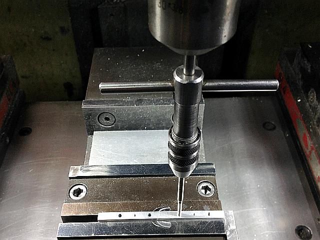
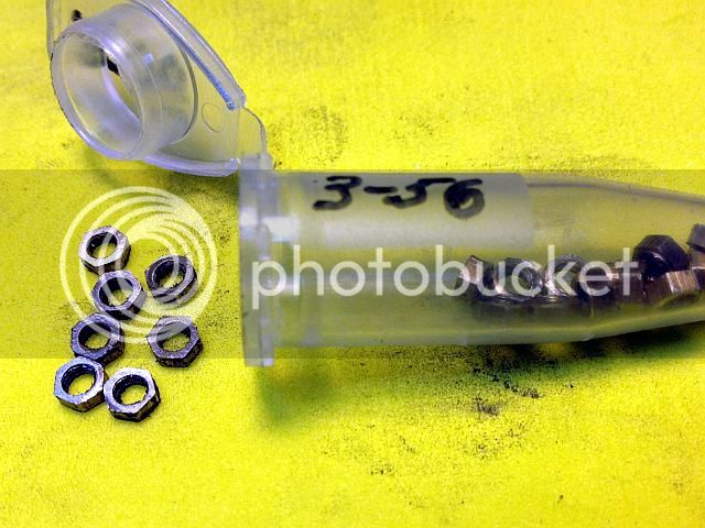
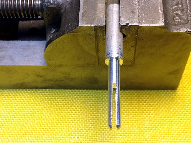
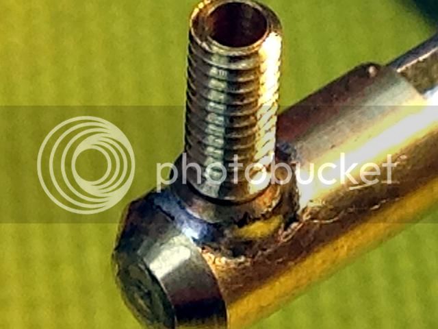
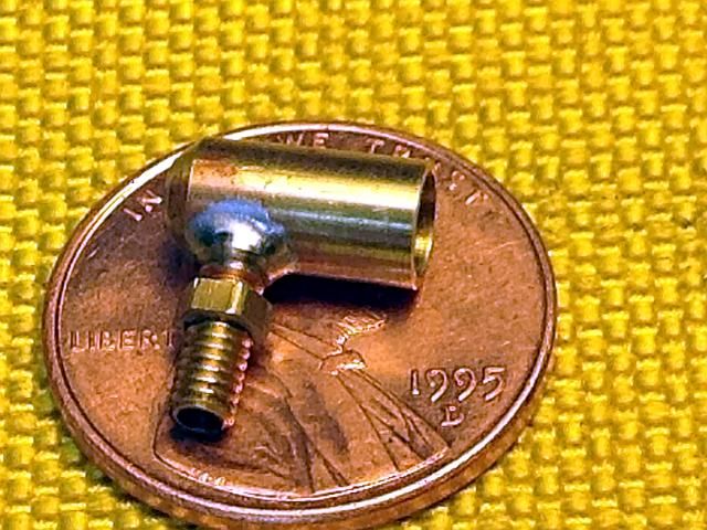
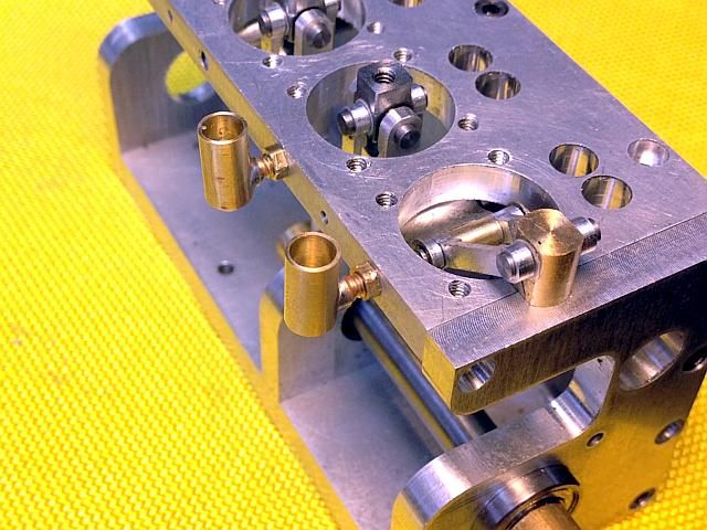
Then it was over to the mill to center drill, drill and tap the oil cup holes 3-56. I know it's not a common thread, but I like it. Not too much to be said about that and really not worthy of a photo, but I did one anyway. Next up the oil cups.
Gail in NM
CrankCase0006_zpsa3a3255e.jpg
 
With the oil cup mounting holes in place I cleaned up the cylinder mounting plate to remove the remaining machining marks. Then it was on to the oil cups.

I normally keep the 3-56 lock nuts in stock as I use a few of them from time to time. I needed 4 but only had 3 on hand so a mini production run of 2 dozen was made. Started by drilling a tap size hole in the end of some 1/8 inch hex stock. I drilled deep enough that I could make 6 nuts. Then cut off the six nuts to 0.055 thick and repeated until I had 24 nut blanks.
OilCup0001_zpsa624f20b.jpg

A collet stop was turned to 0.120 diameter and drilled 0.102 diameter for a depth of about 3/8 inch to clear a 3-56 tap. The stop was installed in the 1/8 inch hex collet I had just used to make the blanks. The stop was adjusted so one of the nut blanks would just fit flush in the collet.
OilCup0002_zps779636b3.jpg

The tap was mounted in a tap handle and was supported by a spring loaded center in the tailstock. The Collet was adjusted so the nut blank just fit in the collet with out closing the collet. I just wanted to keep the nut square and prevent it from turning. The collet was NOT closed as that would distort the nut. Then each nut was tapped.
OilCup0003_zps94627f71.jpg

After a quick rub on a piece of 400 grit abrasive paper to remove the burr raised by the tap the result was 2 dozen jam nuts.
Gail in NM
OilCup0004a_zps947c9035.jpg
 
Next up was the nipple to connect the oil cup reservoir to the cylinder mounting plate. It is just a 3/8 length of 1/8 diameter brass that is threaded 3-56 on one end and the other end left as 1/8 diameter to solder into the reservoir at a right angle. It is drilled full length with a 1/16 diameter hole for oil passage. No attempt was made to restrict the oil flow. The oil will be added to two of the cups when the pistons are at BDC and the oil will flow into the oil groove on the piston. Then the crankshaft will be rotated 180 degrees and the other two cups filled. With cast iron pistons and cylinders this will supply enough lubrication for about an hour of running time after the engine is broken it. More oil will be needed during the first couple of hours of running while the pistons seat in the cylinders.

As I have a small CNC lathe I made the nipples on it. I single pointed the threads. The could lbe made easily on a manual lathe and a die could be used to cut the threads. No in process photos were taken. The finished nipples look like this with old Honest Abe for a size reference. Honest Abe is 19 mm diameter for my international friends benefit. A few extra were made to feed the swarf bunnies.
Gail in NM

OilCup0005_zps54069d62.jpg
 
The reservoir is a short length of 3/16 brass drilled about 1/2 way to 0.156 for the reservoir it's self and then drilled 3/32 diameter with a blind hole to just short of the length. A short length of 3/16 brass was turned down to fit the 0.156 hole and then the rest of it was turned down a little bit to be smaller than the lbody diameter of the reservoir. This was to insert into the reservoir to keep from crushing it when clamping when putting the side hole in. The first photo shows the plug and two finished cups.

OilCup0006a_zps87edbc95.jpg


The side hole was put in by clamping the part in the mill vice with the part resting on a parallel and the plug inserted. A 3/32 end mill was used to drill a connecting hole to the center of the part and then the hole was opened up to 1/8 inch about 0.050 deep for the nipple to insert into.
Gail in NM

OilCup0006_zps8eebbe81.jpg
 
With all the parts made, I made a holding fixture to support them while soldering. It is just a length of 1/4 inch diameter aluminum rod turned down for about an inch to an easy fit in the cup. A little taper was filed on the end to make it easy to fit into the cup. The rod was split on the band saw and the cut deburred. The cut part was then spread a little bit with a screwdriver so it would grip the inside of the cup. It does not take much as all it is doing is hold things while soldering. Besides the rod will probably open up some when it is split. The reason for making it an easy fit in the cup is to minimize the heat transfer from the cup to the fixture while soldering. Here it is clamped in a small vice ready to use.
Gail in NM
OilCup0007_zpsf4213875.jpg
 
Solder preforms were made to do the actual soldering. l also used some electrical non corrosive solder flux paste.

The preforms were made by by winding some 0.020 diameter (0.5mm) electronic solder around an 1/8 inch rod.
OilCup0008_zpsac6f8275.jpg

I put this spring shaped coil on an index card with the card on a hard flat surface and inserted a hobby knife with a #11 blade in the coil and cut the coils apart by pressing down and drawing the knife out. The card protects the edge of the blade and lets the blade cut all the way through the solder. Then I cut a small segment out of each coil with the knife. When cutting the coils apart the blade will expand each coil a bit so the cutout lets the coil close up to be a snug fit around the nipple. Besides a full ring of solder is more than needed to make a good joint.
OilCup0009_zpse28bdd19.jpg

A small amount of flux is put on the end of the nipple. There is usually some in the lid of my flux container so I just scrape a little of that onto the nipple. Only a small amount is needed. If I can see that I have some on the part that is enough. If I can see it easily then that is too much. The flux makes the nipple end sticky enough that a solder ring will stick to it when the nipple is pressed down into it. I inserted the nipple into the cup and a little twisting motion distributes some flux around inside the cup recess. The solder ring was pressed down to conform to the joint. I find it is easier to do all this with the parts held in my finger before putting them on the fixture. The assembly was then slid onto the fixture.
OilCup0010_zps469d4f5c.jpg

A small torch was used to heat the bottom of the cup until the solder flowed. If heated from the bottom the nipple is not over heated. Soon as the solder flows into the joint remove the heat and let cool.
Gail in NM

OilCup0011_zpsf8167f89.jpg
 
Old Abe showing off a finished cup assembly and two cups installed.
Gail in NM

OilCup0012_zps92dbe61e.jpg


OilCup0013_zps800a60d0.jpg
 
The little bits of detail in your posts add somuch to the enjoyment. Thank you Gail.

Jim
 
What Jim said, Gail. The devil is in the details and you've got 'em by the tail;)

Cheers,
Phil
 

Latest posts

Back
Top