Building Jerry's Donkey

Home Model Engine Machinist Forum

Help Support Home Model Engine Machinist Forum:

This site may earn a commission from merchant affiliate links, including eBay, Amazon, and others.
Hey Jerry,

Great build friend! Glad someone is modeling the old girl!

If the gear location problem gets complicated, lots of gears meshing together with eachother, wait to finally locate the shafts until after you cut the gears.

Locate and mesh each gear on a toolmakers button, and once they all mesh the way you want, locate the button with your "Last Word" indicator and bore the shaft hole.....

Works real well.

Congratulations on tackling the gear cutting. Everything is scary the first time, but it is a lot of fun to see them being used after!

Keep it going, I can't wait for the next installment! ;D

Dave
 
Jerry.

Very nice gears.

I enjoy reading your narrative.

SAM
 
Incredible work Jerry. :bow:

I love this method of making gears, and your post is very informative.

Kel

 
Very nice set of gears!
Nicely done what did you use for grinding your tooth profile on your cutter?
Now don't laugh when I've done this I have used my machinist hand book photo copied the tooth profile section and hand ground cutter to match I know real precision but it has worked. I was just wondering how you got there.


Again nice set of gears! :bow:
 
Many thanks to those who drop in and leave a message.

Dean, Bogs, Kel, Sam, Dave, Doc,

Your kind comments and words of encouragement are really appreciated.

I'm not often interrupted in the shop. It's 1/4 mile distance from the house keeps all but the truly motivated at bay.

Doc, the profile that I used for both the gear and pinion came from Rush Gears, Inc. Their website has a utility that lets you input the common parameters and then import a 2D or 3D CAD file with the output.

Jerry
 
This is great! Keep it up! Thm: I can't wait to see it in operation.
 
Locate and mesh each gear on a toolmakers button, and once they all mesh the way you want, locate the button with your "Last Word" indicator and bore the shaft hole.....

Hi Dave, can,t quite get my head round the above ...the tool makers button bit...are these the buttons with a shaft size hole allowing for positioning and then locked down...a c.o.c. would be a great help.
All the best for now,
john.
 
kellswaterri said:
Locate and mesh each gear on a toolmakers button, and once they all mesh the way you want, locate the button with your "Last Word" indicator and bore the shaft hole.....

Hi Dave, can,t quite get my head round the above ...the tool makers button bit...are these the buttons with a shaft size hole allowing for positioning and then locked down...a c.o.c. would be a great help.
All the best for now,
john.

John,

Will do!...give me a bit while I cook dinner for the kids on the Barbi....... ;D

Dave
 
OK

Here we go....

http://i164.photobucket.com/albums/u27/mcandrew1894/toolmakersbuttonexplaination.jpg

Now in the last step, once the button is located under the spindle, or concentric to the spindle, then and only then do you remove the button and screw. Start the hole with a center drill, then an undersize drill, then if at all possible, bore to a few thousanths undersize. Then finish with a reamer..

The extra boring step, is to make sure the hole is concentric with the axis of rotation, as drills will "walk" out of position, especially if there is a tapped hole in the cut zone. The boring bar will fix any of that. The reamer just sizes the hole.

I have a partially finished build of my "Seadog" that shows some pictures of my set up for boring the camshaft bearings, after I located/meshed the gears with a toolmakers button. That may help too....need to get that engine done....too many projects!

http://www.homemodelenginemachinist.com/index.php?topic=3951.0

Dave

 
Hi Dave,
Thank you very much for the c.o.c. ...sort of kick starts the old brain again after about forty years ;) do hope the kids enjoyed the barbie, :)
All the best for now,
John.
 
Dave

The use of buttons might be a good idea but its too late for me to do it the right way. I just set the gear and pinion on short pieces of 1/4" shaft held vertically in v blocks. When they were in mesh, I measured the spacing (to outside shafts - 1 shaft diameter) and it was as close to 1.50" as my cheap calipers could tell me. Since that was exactly what I was hoping for ((2.5DP + .5DP)/2) I was satisfied. I popped a mark where I wanted the hoist shaft and then using dividers, struck an arc across the front face of the "A" frame to locate the pinion shaft.

The front shaft has not been located yet as it will be on axillary frames bolted to the front of the main frame. I won't do that until I have the "A" frames located on the deck with all of the hoist machinery (clutches, brakes, and drum fitted.

I have wondered about the lack of adjustment for these shafts on the prototype. Maybe it is because these are open, slow speed gears with very wide faces. The original uses split bronze bushings and there is no evidence of shims.

Jerry

 
No worries Jerry!...It runs therefor you did it right!.... ;D

Pay no attention to me....

Lots of those winches had cast teeth.....lots of backlash, no need to worry much about gear mesh when the teeth are 3 inches tall... :big:

Dave
 
Captain Jerry said:
Starting time:

Jerrysdonkeygears021.jpg


Finish time:

Jerrysdonkeygears022.jpg

And I thought I kept late hours. Didn't the neighbours complain? ;)

Seriously, I am very much enjoying your build, and thanks in particular for your gearcutting details.
 
T70MkIII said:
And I thought I kept late hours. Didn't the neighbours complain? ;)

T70MkIII

When its late over there, its early over here. I have to get an early start before the heat overcomes the small air conditioner in my shop.

There is enough gear cutting information and help available right here on this forum to give a novice like me the confidence to take on the challenge. I am very happy with the results and I hope my experience helps to motivate others to try something a bit beyond their comfort zone. Whatever it is, there is plenty of help right here.

Jerry
 
I got a little bit done today. I needed to get away from the clutch thing today. Too much tension and I picked up a nasty cold from my great-granddaughter who went visiting somewhere and brought it around to share with us.

The hoist drums are just big spools with the clutch/brake drum as one flange and a plain flat flange on the other end. They freewheel on the shaft waiting for the clutch to move them so today I tackled the core of the spool. Starting with a piece of brass pipe, I turned some brass bushings from some smaller pipe. The shoulders are just to keep them from disappearing down the bore when I solder them.

Jerrysdonkeydrum007.jpg


I may have said this before but soft solder ain't hard! There is one important trick that must be followed thought. Don't let the heat escape! Even with a very small butane torch and a big piece of brass, you can bring both pieces up to temp and keep them there while the solder flows and the flux doesn't burn as long as you don't let the heat escape through clamps or vises. I try to keep the pieces isolated as much as possible so the heat has nowhere to go. In this case the pieces fit tight enough that I can suspend them from a piece of wire with minimal contact. If clamping is required, I will make small spring clamps with pointed contacts so they don't take away any heat. Apply the heat to the larger piece, watch the flux flow, touch the solder to a point on the far side of the joint and watch it melt and flow into the joint. You can then take the torch away and touch the solder anywhere around the joint.

Jerrysdonkeydrum009.jpg


I didn't have enough hands to hold the torch, the solder, AND the camera so that's he best I could do.

The work piece will stay hot enough to flow the solder for several minutes after you remove the torch if you don't let it escape into a vise or a big clamp. You need to leave the pieces undisturbed for a few minutes so they cool and the solder sets before moving them. It works for me so I thought I would pass it on.

Jerrysdonkeydrum010.jpg


When they have cooled enough, I dunk them in water and give them a good wash with detergent and a brush. Excess solder can be trimmed on the lathe or with files. In this case, the pipe that I used for the bushings did not reduce the ID enough so a second set of bushings was made and the process repeated. The second set extends beyond the end of the large core to seat the clutch drum and the end flange.

The clutch disk is a really big piece of brass that I couldn't support on a wire so I stood the assembly on end to keep contact to a minimum. Once the piece had absorbed enough heat, the solder flowed smoothly and there was no hurry.

Jerrysdonkeydrum011.jpg


After it cooled a bit I turned it over and you can see that the solder penetrated the full depth of the shoulder.

Jerrysdonkeydrum012.jpg


The next step was to clean the piece up and true it up in the lathe. That's it for today but I am beginning to feel a lot more confident about the outcome of this project. I seem to do better under a deadline so I hope to post.... No I WILL post a video of the donkey running by the end of next week!

Jerry
 
I am now into the inner workings of the clutches. American Hoist & Derrick Co. of St. Paul, Mn, (hereinafter referred to as AMHOIST), used hard maple blocks as friction material in these clutches, and according to their literature, these friction blocks almost never needed replacing. Sounds like a good choice of material. I'll try it.

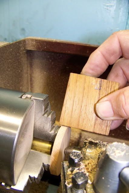
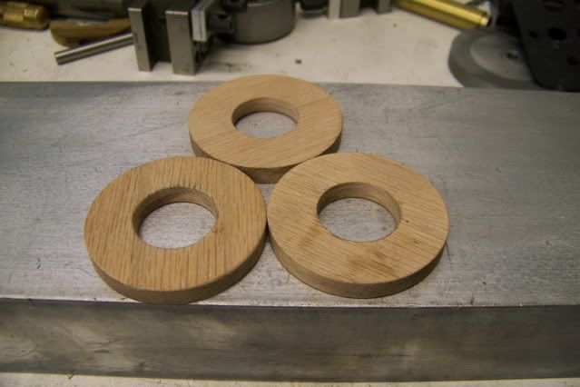
I don't have any maple handy and I'm not sure that it is the right thing anyway. It's a matter of scale. You can't buy an 1/10th scale maple. All the maple ever grown is from full size maple with full size cellular structure. There may have been 1/10th scale maple trees grown in the land of Lilliput, but I cannot find a website for Lilliputian Lumber so I will improvise. Maple is not available here, but Lowes has oak in a very convenient size (1/4" x 2 1/2" x 24" ) so that's where I'll start. Carefully selecting a piece with vertical grain to minimize cupping, I hacked it into little squares with my hacksaw and pressed it against the lathe chuck face with the live center, just like making a flywheel disk out of aluminum brass.

Jerrysdonkeyshoes001.jpg


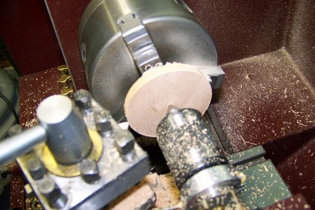
Oak is very hard and machines easily. The swarf is soft and fluffy and fills up the chip tray pretty quick but the method worked very well. I have spent a LOT!! of time in front of a wood lathe and would never have done it that way before. I was a little concerned that to much pressure with the live center point might split the wood. A proper woodworking approach would use a live cup center but I had no problem at all. The cutting force is so much less that I didn't even need to use double sided tape or anything between the wood and the face of the chuck jaws. Just pressed it up firm with the tailstock.

I used a very sharp HSS bit and it left a nice cut on the edge of the oak. If I were going to apply any type of finish, I might touch it with a little sandpaper but this is going to be a friction face so I burnished it to a hard finish by pressing another piece of wood against it while turning in the lathe.

Jerrysdonkeyshoes002.jpg


The disk was then gripped with the outside jaws and the center was bored to 3/4" ID to clear the hub. I made a few extras. Who knows what will happen?

Jerrysdonkeyshoes003.jpg


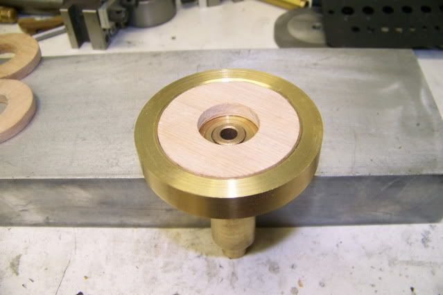
It looks like I am making a friction pad that will make face contact but I am actually making two pads that will expand radially and make contact on the edges. The pads need to have the same radius as the ID of the clutch drum so it starts out as one disk that fits inside the clutch:

Jerrysdonkeyshoes004.jpg


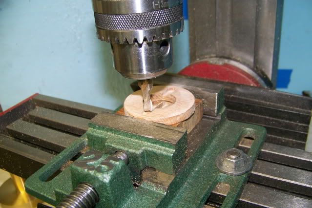
And then gets cut into two separate shoes. Before it gets cut, I transferred it to the mill and cut to dead end slots, .15" deep, at 180 degrees apart.

Jerrysdonkeyshoes005.jpg


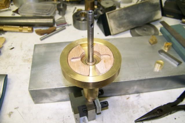
These slots will be the only connection between the shoes and the actuator plates on the drive gear. I don't know if this will work. I don't want to use adhesive and I cannot figure a good way to use a fastener. I want the shoe to have a sort of floating ability so that outward pressure will seat it against the clutch drum. I had nightmare visions of a loose screw floating around it the works and wreaking havoc, so no screws

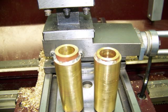
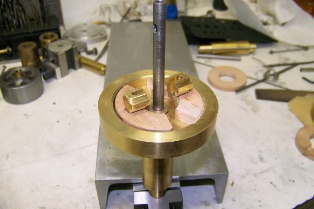
Here are the shoes in the clutch drum:

Jerrysdonkeyshoes007.jpg


Here are the actuator plates sitting in the slots for visualization only. They will actually sit in slots in the gear and protrude into slots in the shoes.

Jerrysdonkeyshoes009.jpg


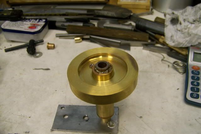
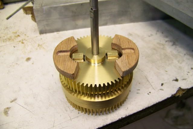
This is the back side of the gear with the protruding plates.

Jerrysdonkeyshoes014.jpg


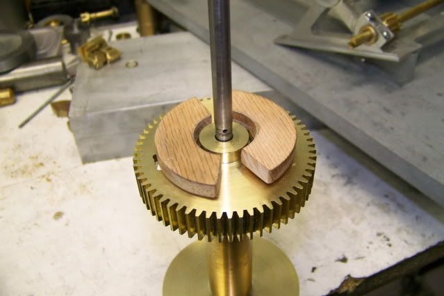
The shoes will be flipped over and the slots and the protrusions will match up looking like this

Jerrysdonkeyshoes013.jpg


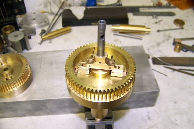
Then the whole thing goes together like this:

Jerrysdonkeyshoes011.jpg


In the above pic, downward pressure on the crossbar forces the actuator plates outward through small links that are barely visible. You can refer to an illustration in a previous post for a better view.

Here is my problem! The length of these link bars is critical to getting equal pressure and movement to the shoes. The AMHOIST prototype uses a threaded bar for this adjustment link but that is out of the question in 1/10th scale.

I don't think I have the answer. Your comments and suggestions are solicited! I need to get a grip on this. Otherwise my commitment to posting a video of the donkey running by the end of next week is in jeopardy!


Jerry
 
Jerry,

The amount of differential movement required is going to be very small.

Could you open out the centre of the main operating bush by say 0.010", and it's locking pin hole in the main shaft by about the same amount, but still retain the pin size in the main bush, so that the operating bush is actually 'floating' around the shaft, but still getting drive thru the pin.

That way, if one of the shoes comes into contact first, the 'float' would still have enough movement to allow the second shoe to come into contact as well. A sort of self centring effect.

I doubt if that little float would be noticeable on an engine of this size.

I hope you understand the method, and it is only a suggestion.


Bogs

 
Jerry,

Is it possible to:-

1. Shim the laggard link.

2. Reduce the length of the slot in the laggard clutch timber.

I realise we are talking small numbers here but.................. just a couple of thoughts to complement bogs suggestion.

Best Regards
Bob
 
Here's my fourpenneth,once the shoes are applied a few times I feel that they will wear in that few thou,knowing you will have got them as near as damn it.
Don
 
To echo Bob and Don's posts, can the assembly be locked in place and machined concentric to the shaft?.....( On the lathe or on a rotary table on the mill...ect)

Once close, it will wear in fairly quickly I think.


Dave

PS.... in looking at the illustrations posted earlier, I think you could machine these.

I would make up a sacraficial face plate ( held in a 3 jaw or what have you but faced and bored in situ just prior to use)
Mount the assembly on the shaft but minus the clutch drum. If you make a clamping washer that fits with clearance over the central hub, but clamps the shoes to the faceplate in their natural location ( positioned radially by their own links), then take a slight turning cut on the shoes to make them concentric. The clamping washer could be held via a custom bolt with a body diameter the same size as your clutch shaft.

Here is the COC.....hope it helps!

Jerrysdonkeyclutchproblem.jpg


Dave
 
Back
Top