Building Jerry's Donkey

Home Model Engine Machinist Forum

Help Support Home Model Engine Machinist Forum:

This site may earn a commission from merchant affiliate links, including eBay, Amazon, and others.
Jerry
I know the fear and the elation...LOL. I cut my first gears on my last engine project and sweated bullets. Congrats on a successful adventure. The gears look great!!

Now, if I can figure out all the angles, my next gear cutting will find me doing bevel gears with the single tooth cutter. I've really gotta make up some hobs one of these days.

Steve
 
Steve,

If you do miter gears with a special twist as you always seem to do it will probably turn out to be a spiral bevel gear, with flourishes.

Today I made a startling discovery. It takes 5 times as long to make a 60 tooth gear as it does to make a 12 tooth gear. Go figure! I made the 60 tooth gear out of 3/8" aluminum for practice and to work out some dimensions and clearance issues on the clutch mechanism before committing thirty dollars worth of brass an to make sure I understood the dividing head process. 1. Table right to cut the tooth. 2. Table left to clear the cutter. 3. Mill motor off. 4.Open the RT lock. 5. Crank the RT. 6. Advance the plate quadrant. 7 Mill motor on. 8. repeat 60 times.

Its kind of like drinking tequila shots with salt and lemon. 1. Lick the salt. 2. drink the tequila. 3. Suck the lemon. After a while, it is easy to lose your concentration. No big deal if you get the salt and the lemon in the wrong order. I doesn't affect the outcome. I'm not sure what happens if you screw up the gear making order.

Here is the process under way:

Jerrysdonkey2027.jpg


Jerrysdonkey2028.jpg


Here is the finished gear:

Jerrysdonkey2030.jpg


The gears mesh nicely. They seem to run together smoothly. And the centers are exactly 1.5" apart as planned. This is important because there is no provision to adjust the shaft locations on the donkey frame. I needed this dimension confirmed before proceeding with building the base and hoist frames.

The hoist gear is recessed to mount the clutch mechanism that drives the hoist drum from the gear. I will get to that soon.

Jerry
 
I may not be the most organized poster on this forum. If it looks like I'm just jumping around willy-nilly, I plead guilty. On the way to the shop this morning I'm thinking that now that I have confirmed the between center spacing on the gears, I should go ahead and finish the base and frame. I could locate all three shafts and get the bearings in place.

It didn't work out that way. I'm sure that I have two pieces of TGP 1/4" steel rod set aside for this project but it was not to be found. It will turn up but now what do I do today. A little voice in the back of my head said "Why do you keep putting off thinking about the clutch?" Once called out, I could no longer avoid the clutch.

Here's the problem. Lots of fiddly little parts. The way a hoist works is not all that obvious, so if you haven't thought much about it, I'll run through the basics.

When the engine is turning, all shafts are turning. The pinion gear is fixed on the crankshaft. The pinion gear meshes with the two big hoist gears which are fixed to their respective shafts. These three shafts run in bearings on the hoist frame. The pinion shaft and the main hoist shaft are mounted on the same "A" shaped upright, hoist shaft at the top of the "A" and the pinion shaft low on the front leg of the "A". The front hoist is on top of a separate frame that bolts to the main frame. The capstan drums on outside of the left side of the hoist also turn whenever the engine is turning.

The hoist drums do not turn unless the clutch is engaged which connects the drum to the hoist gear. Otherwise, it freewheels on the shaft on another set of bearings. If the brake is engaged or the pawl set, the drum is stationary with the shaft rotating inside the drum. The brake is a strap around the outside of a brake drum. The pawl can be set to engage ratchet notches in the edge of this drum. The inside of the brake drum is a clutch face. Friction shoes are mounted on the inner face of the hoist gear and when expanded or pushed outward by the clutch mechanism, they bear on the inner face of the clutch/brake drum causing it to rotate under operator control.

Larger hoist have separate brake and clutch drums at opposite ends of the hoist drum so that clutch friction heat doesn't affect the brakes but on small hoist such as this they are one piece.

Here is a picture of the clutch linkage:

Donkey006.jpg


On the prototype, each drum has four clutch shoes and you can see the adjusting nut on each linkage arm and the spring which forces the friction shoe away from the clutch drum when the lever is released. To build this in 1/10th scale would be like building a pocket watch. Too much for me.

My approach will be to design a linkage that retains the principal but is simplified to buildable proportions. I will use a two shoe design (half the part count) and a single common spring.

I get nervous when writing long descriptions like this. Laptop batteries and fat fingers have blown away some posts in the past so I'm going to post this now and continue a new post.

Be right back.
Jerry

 
Here is the two shoe version in Alibre'.

SpiderSliderNew1.jpg


Above is disengaged, below is clutch engaged, pads pushed outward.

SpiderSliderNew2.jpg


It works the same and is a lot simpler but still very small parts, the smallest I have ever built. Here is the results of today's efforts. The gear is my test aluminum gear because there is still room to screw it up.:

Jerrysdonkey2039.jpg


The first step is to cut the openings in the gear web. The mechanism is on the outside, and the shoes will fit on the inside when they are installed. The rotary table in use, and I now understand the limited "Z" axis problem. I learned from this exercise that the openings need to be longer to allow full and free movement.

Jerrysdonkey2031.jpg


I spent a lot of time with small pieces of brass in the toolmakers vise and an 1/8th inch end mill. The next pic is of the back side of the gear with the linkage showing. The clutch friction material will attach to the links showing through the gear.

Jerrysdonkey2037.jpg


Dinner is on the table, gotta go, more latter.

Jerry
 
This is one of the most enlightening posts I've read.
thank you.

beautiful work.

tom
 
Jerry,

Like most things, when going to a smaller scale, they can't be directly scaled because of what you found, things become excruciatingly small, and of course, in that small size, they will not work like the real thing, they are not 'man enough' for the job in hand.

This is where artistic licence comes in, just like you have done, and made it so that it will function the same as full sized, and what a great job you have done with it.

Excellent work indeed.


Bogs
 
Great thread.

When cutting the large gears, did you cut full depth for each tooth? I thought you were going to gash first with a slitting saw, but the pics look as if you finished each tooth before starting the next.

This model is going to be special wheen complete.
 
Tom,

I'm glad you find this enlightening. This has been a huge learning process for me as well. Lots of time spent investigating and planning.

Bogs,

Thanks for the kind comments. This is what I enjoy most about this hobby, making thing that work. There are so many ways to do it. Simple ideas turn into complex solutions, for example take "Piston pushes rod, rod turns crank, turns shaft, turns flywheel" is a simple idea but the work displayed on this forum just touches on the countless ways it can be done. Great fun!

Kvom

I did cut the big gear in one pass. I made two passes on the first pinion because I wasn't sure what to expect. The second pinion was cut it one pass. The cutter for the pinion actually removes more material in one pass than the big gear so when I got to the big gear I was pretty sure that I would be OK.

Its a good thing because when I got all set to make the first cut on the big gear, I found that I was at the end of the "Y" travel on the mill. I couldn't have cut the gear in two passes if I had wanted to. Fortunately, I had scribed a mark on the face of the blank to indicate the tooth depth and the tip of the cutter was dead on the line! If I ever have to make a bigger gear, I'll have to rethink the setup.

I don't think that I would try this on anything hard like steel.

Jerry
 
Good going with the larger gear, Jerry. A very neat way you figured out how to set up the clutch and shoes, too. Looks very nice!

Dean
 
Tomorrow, the UPS truck will bring about $40 worth of brass for the hoist gears and the brake/clutch drums. I hope to see some real progress now. I have been getting to know the ins and out of the rotary table and I have just one question about it.

Why does everything that seemed impossible before, now seem to be possible . Really, How did I get by without this thing. You guys that have one know what I'm talking about. If you don't have one it should be your next purchase, without a doubt. I bought the $159 Grizzly 4" with dividing plates and I thing it is a lot of bang for the buck. As you should expect, for this price, you will have to spend some time cleaning, filing and polishing, but the end result is very usable. The only real problem was the mechanism that locks the eccentric barrel that is used to adjust the backlash int the worm gear. It came in contact with the lip on the housing before it drew up tight. A small brass washer raised it above the lip, gave it more working room and made for smoother operation.

I roughed out the A frames and the shaft bearings today. I have decided to use oillite sintered bronze bushings throughour. Verry rough but it begins to take shape. The frames and the bearing caps still need to be profiled.

Jerrysdonkey2042.jpg


The purpose of this exercise is just to confirm the relative locations of the two shafts and the meshing of the gears. I don't know what I was worried about. No problems. The gears mesh nicely and the shafts rotate smoothly. Here's a video:


Just finger powered but its progress.

Jerry


Jerry
I'm really enjoying following this build. You're doing a fantastic job!!

Steve
 
Jerry,

Your Donkey is really moving along.

It won't be long before we hear it braying.

SAM
 
Steve and Sam,

Thanks for the interest in this project. I feel like it is beginning to come together even there are many more challenges.

The UPS truck arrived with my material but it was to late in the day to do much more than unpack it. I only wanted enough brass for the gears and the drums, but as usual, they sent way more than I needed. By the time I have chipped of the excess, the weight will have been reduced to about half what it is now.

Jerrysdonkey2056.jpg


Hopefully I will begin the chipping process tomorrow. I don't work nights.

Jerry
 
The assembly picture and finger power look great, Jerry. For a fellow who's never done this stuff,
we'd never know it!

Dean
 
This is a brilliant post,thanks for sharing,I'm loving it.
Don
 
I think I got a lot done today so this might be a long post. If it gets to be too big, I'll break it into 2 or more bits.

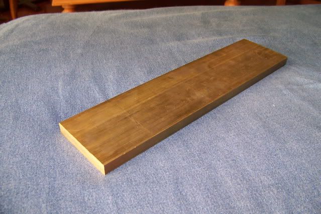
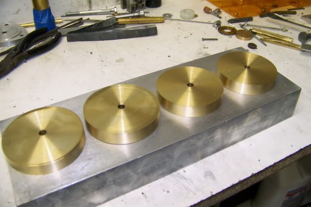
Starting with the hunk of brass above, 3" x 1/2" x 12", I hacksawed it into 4 pieces 2.7" x 2.7" x 2.7" x 2.7" (thats 8 sides). Much easier than sawing aluminum.

Then, using Bogs' flywheel method, I turned it into 4 disks 2.6" diameter.

Jerrysdonkeygears003.jpg


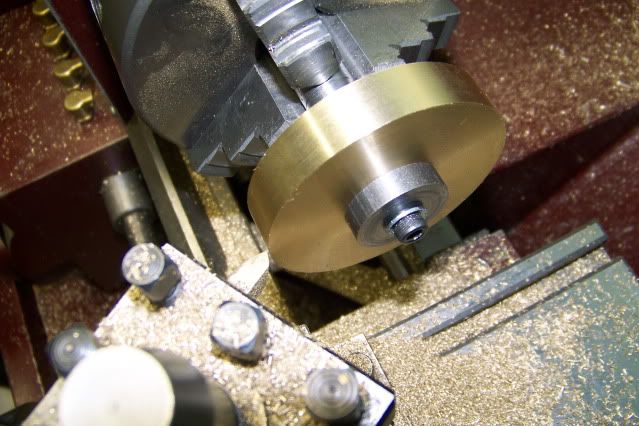
Then gripping each in the 3 jaw, faced one side, flipped it around and faced the other side and then drilled and reamed a 1/4" hole for mounting on a mandrel.

I then mounted each on the mandrel and took a final cut to bring it to 2.58" (OD for the gear).

Jerrysdonkeygears002.jpg


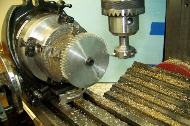
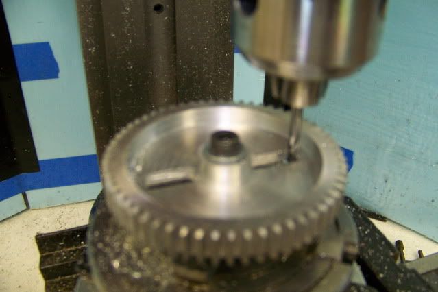
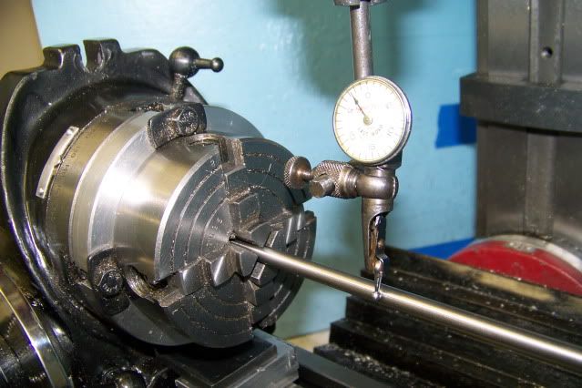
Then I setup the rotary table for cutting the gears. First centered a 1/4" shaft in the 4 jaw and checked that it aligned with the "X" axis. There are keys on the bottom of the rotab for this but I had never verified the alignment so I checked. Turns out the keys were good enough.

Jerrysdonkeygears006.jpg


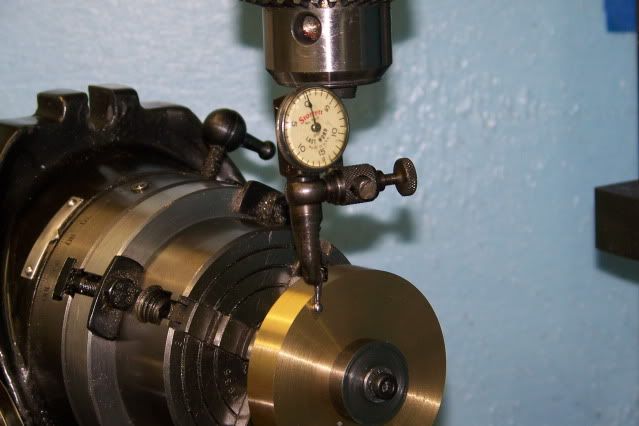
Then I centered the mandrel in the 4 jaw and mounted one of the gear blanks, and checked again. Good enough.

Jerrysdonkeygears008.jpg


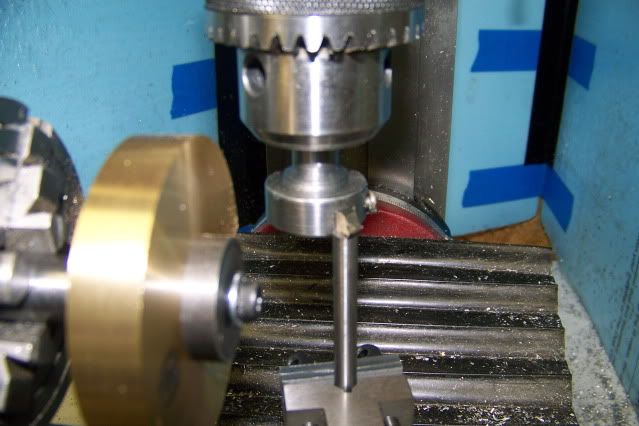
I then checked the single point cutter that I had used on the trial aluminum gear. The edges seemed sharp but I decided to dress them with a stone before starting. Mounted the holder and set the tip of the bit on center. I tightedened the "Z" lock, set the depth stop for added security, checked and tightened the "Y" axis clamp, checked and tightened the Rotab hold down clamps and then checked everything one more time. I think I was stalling. Once the first tooth is started, you're committed. I had experience a little "bit creep" previously so before starting, I decided to make a height guage.

I'm called for dinner: I'm back, edited above to add pics.

The height guage is a piece of 1/4" tool steel held in a v-block and set to just touch the bottom of the bit. I can use it periodically to be aware of changes in the bit height.

Jerrysdonkeygears009.jpg


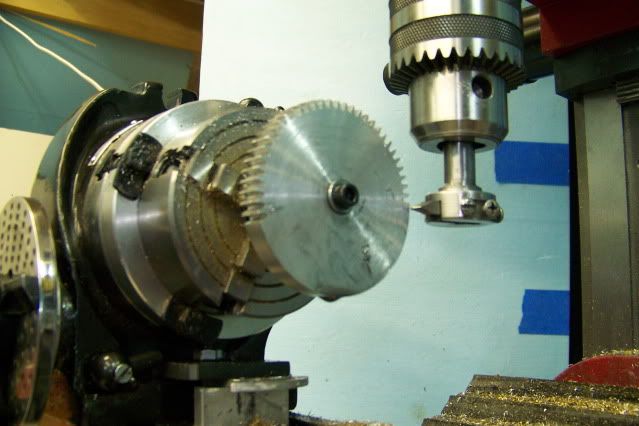
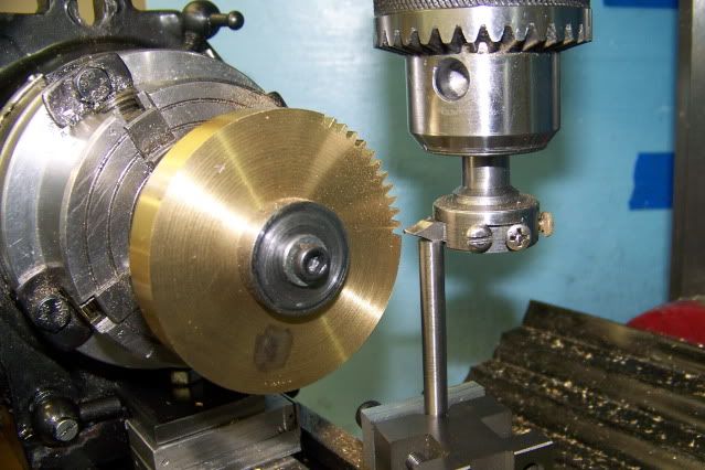
Nothing left to do but get on with it. Taking full cuts at 2500 RPM, the brass cuts nicely. I cut a few teeth and used the guage to check the height. All is good.

Jerrysdonkeygears016.jpg


To cut the full 1/2" gear face takes 16 turns on the "X" crank. I'm a little tentative at first but its better to keep the feed steady and full. I find that I can take about 2 rotations per second of feed without complaint from the machinery. By mentally counting, "one (turn) chimpanzee (turn) two (turn) chimpanzee (turn), I can keep an even feed rate and keep my thoughts from wandering.

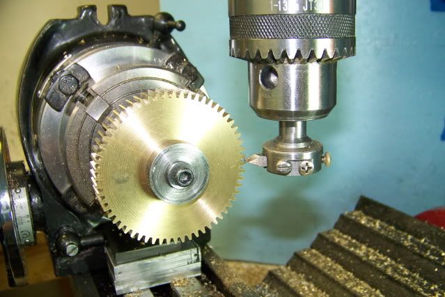
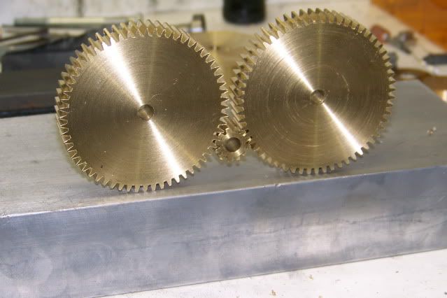
All goes well and in a little over an hour I have 60 teeth on the gear.

Jerrysdonkeygears018.jpg


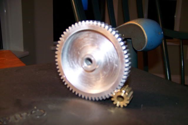
It meshes with the pinion and I feeling confident so on to gear # 2.

Jerrysdonkeygears020.jpg


I think Ive got the technique down pretty solid so I'm going to try to work straight through it. Starting time:

Jerrysdonkeygears021.jpg


Finish time:

Jerrysdonkeygears022.jpg


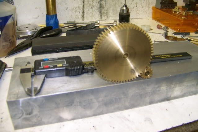
40 minutes from start to finish, 1.5 teeth per minute. I could do this all day.

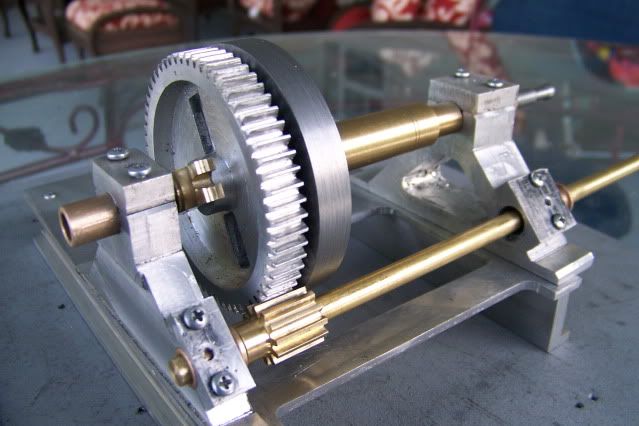
Two gears and pinion mesh nicely.

Jerrysdonkeygears024.jpg


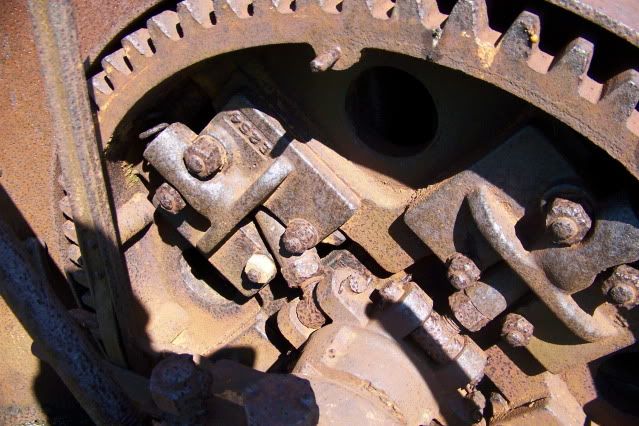
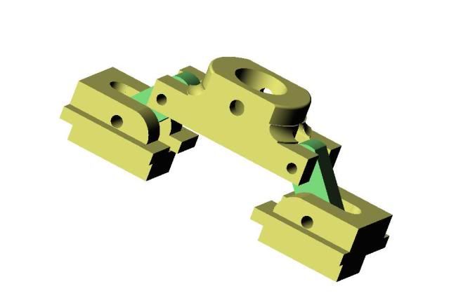
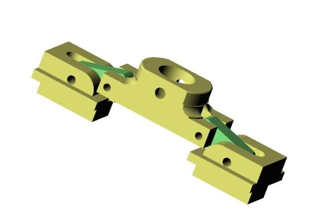
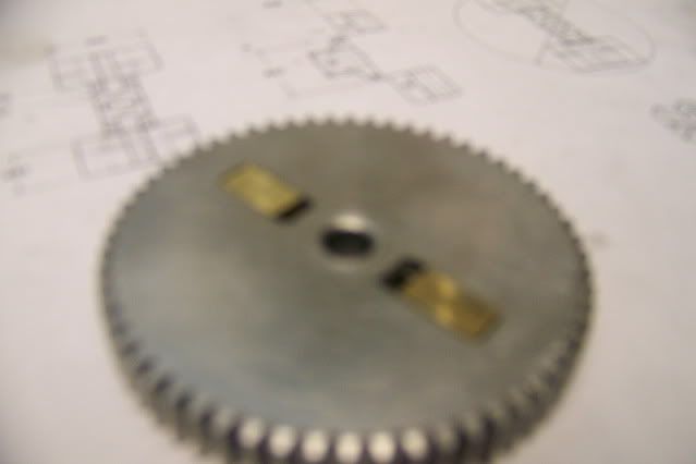
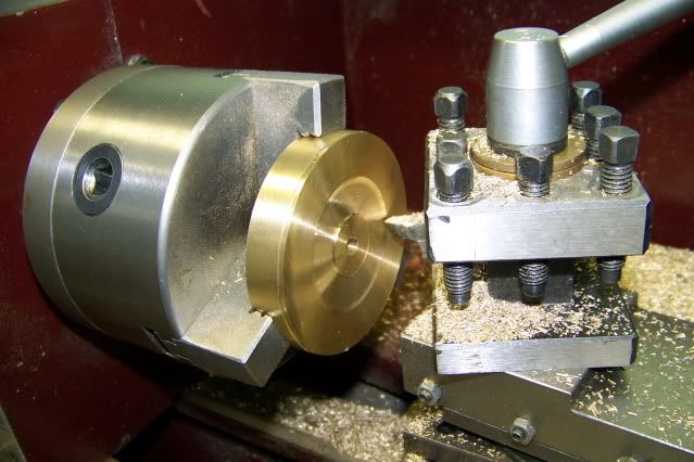
Both gears now must be trepanned (I learned this word here, hope I'm using it right. The cut should be 3/8" deep, leaving a 1/8" web between the hub and rim. Hub diameter .75", rim ID 2". Flat bottom, square corners. I'm going to use the same tool that I turned and faced the blank with. HSS, 80 degree pointed, no rake, flat on top, sharp and polished. The tool holder is oriented so that the tool is pointed toward the front of the lathe, with the one edge 5 degrees off of the face and the other edge 5 degrees off of parallel with the axis. It is positioned on the far side of the lathe axis:

Jerrysdonkeygears027.jpg


To set the final depth, the compound slide is advanced to the limit of its travel. The carriage is moved up until the cutter touches the face and locked. The compound is then backed off of the face by 3/8". The carriage is then unlocked and moved up until the cutter again touches the face and LOCKED! I can now adjust the depth of cut using the compound and know that I will not exceed the final depth. When it reaches the end of its travel, the depth of cut will be 3/8".

I'm going to take the first cut on the far side of the lathe axis with the lathe running in reverse. My threaded chuck mounting has a clamp that prevents it coming of in reverse. The first cut begins just beyond the hub diameter to a depth of about .025" and proceeds across the face of the gear towards the far edge, stopping before the cut reaches the rim ID point.

Jerrysdonkeygears028.jpg


Five or six cuts of this depth are made across the face before the cutter is withdrawn from the hole and moved forward to the front edge of the rim just short of the rim ID point. Now with the lathe turning in the normal forward direction, facing cuts are made across the blank.

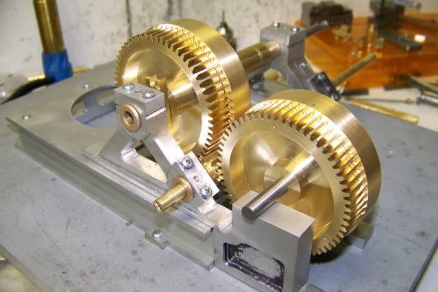
I hope this is clear because I seem to have lost the pics! Sorry. I can try to get some more tomorrow if anyone needs them. I continue working this way, occasionally shifting from font to back, forward to reverse, until I reach the end of the compound travel. I am at the bottom of the cut. The carriage is still locked. I can now take a penetrating cut at the rim ID and face toward the hub, leaving a square corner. Then I shift to the back and make a penetrating cut at the hub and face off towards the rim (at the back) leaving a square corner and the bottom of the cut is dead flat.

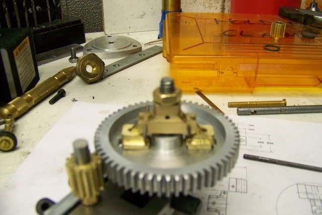
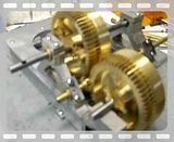
You can see the result in this pic:

Jerrysdonkeygears026.jpg


Here is another finger power video to show both gears in mesh:


Leaving the carriage locked, I can take the part out of the chuck and replace it with gear #2 and do the same thing to it with identical results. Before taking the gear out of the chuck, I take several facing cuts across the hub, reducing its thickness by .25" below the face of the gear. This is to make room for the clutch mechanism.

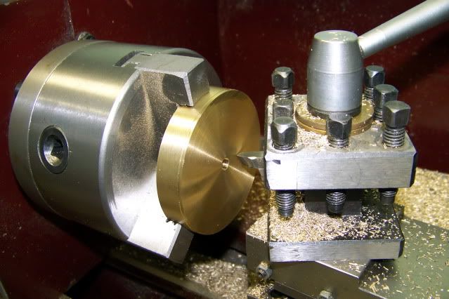
The same type of trepanning cut must be made across the face of the clutch/brake drum blanks to make room for the internal expanding clutch friction shoes.

Ill get some shop time tomorrow but no time for evening report. Wife is taking me to a concert.

Jerry

 
A foot note to the above.

A few months ago my wife enticed me to take her and some visiting friends on a little excursion to to a quaint villiage full of antique shops. What a wonderful idea! I was promised a good corned-beef sandwich with a cold beer for lunch if I was well behaved.

At the second shop, I came across a felt lined tin box containing an antique Starret Last Word dial test indicator. I paid $25 for it but I have a feeling it was worth a lot more.

I didn't tell my wife. No sense risking my beer and sandwich reward!

Jerry

 
You did these up very nice, Jerry. Quite a bit done for one day.
They look great.

$25 for a Last Word is a good deal. They still make them, but they're a lot more than that now!
Thanks for the new post.

Dean
 
Absolutely great stuff Jerry.

I really like write ups where I seem to be there with you, enjoying each cut, and how you are using simple little things just to check your progress as you are going along and making sure you don't make a silly mistake.

I find cutting gears and flywheels very relaxing, just as it seems you do, but really it is a job where you definitely need no disturbances. Some sort of mantrap outside the workshop door is needed.

The feeling when they mesh like yours do makes you want to do more and more, just to prove to yourself that you are in fact doing things right.

That is the wonder of making bits from raw materials.

Because you can !!

Each step learned allows you to go up one rung of the ladder, giving you the confidence to make more complicated pieces.


Bogs


Back
Top