Building a 120mm rotary table

Home Model Engine Machinist Forum

Help Support Home Model Engine Machinist Forum:

This site may earn a commission from merchant affiliate links, including eBay, Amazon, and others.
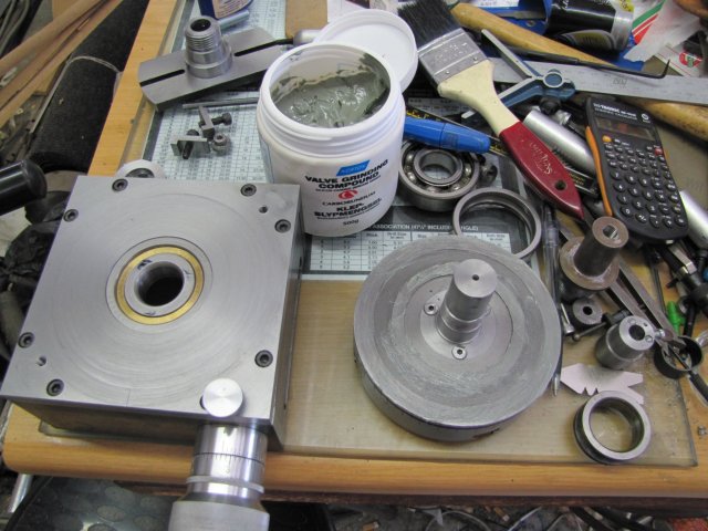
Well, the weekend's gone and there are still loose ends. Fortunately the chuck adapter is done.

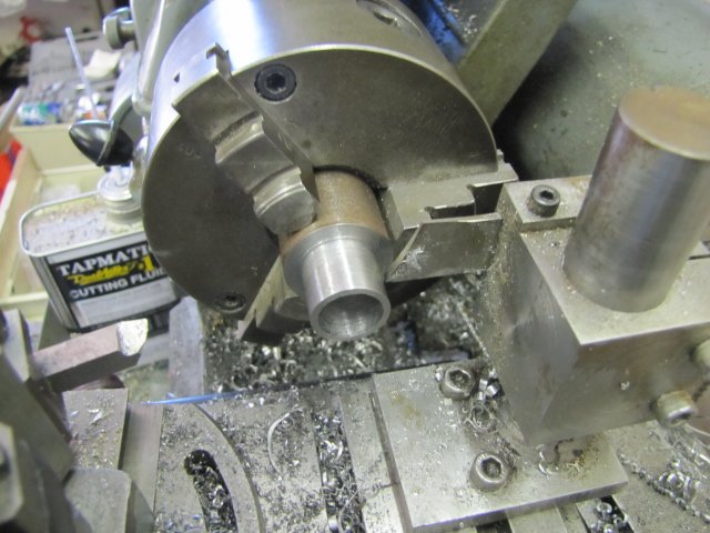
I started by turning a ring from some scrap HRS rod - for a light push fit into the "register" hole I bored in the RT's table. Here, it's done and I'm about to part it off:
normal_IMG_1402.JPG

The ring's purpose will become clear later...

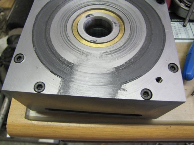
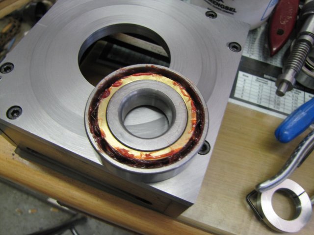
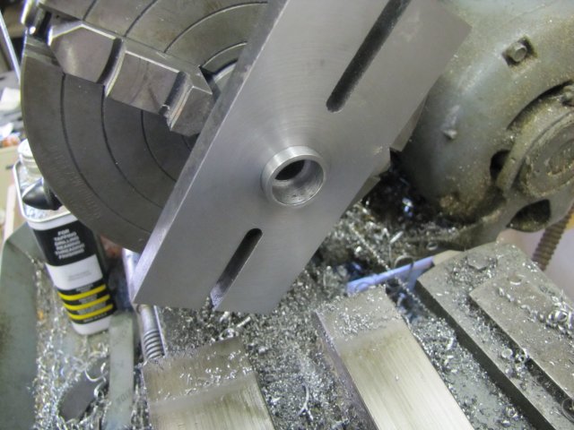
Then I chucked the assembly I made yesterday in the 4-jaw, and roughly centered it - checking that I would need to remove a minimum of metal from the bottom to face it. I then faced it, drilled and reamed a 12mm hole through the center, and bored out a section to fit the ring made earlier, but with the ring a slightly tighter push fit; easily removable, but not inclined to fall out on its own:
normal_IMG_1404.JPG


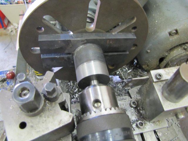
Next I cheated a bit. The workpiece has to be accurately turned around and re-mounted to keep both concentricity and axial alignment to the mounting face. I know that my lathe's tailstock and drill chuck is VERY close to perfect alignment with the spindle - less than 0.005mm out on offset, and extremely accurate in line - I can't even measure this. So instead of setting the job up in the 4-jaw and centering it, I mounted the face plate, and with a bit of 12mm silver steel chucked in the tailstock, used it to mount the workpiece to the face plate. No mess, no fuss, and as well aligned as I could have made it with the 4-jaw; just a LOT quicker ;D :
normal_IMG_1405.JPG


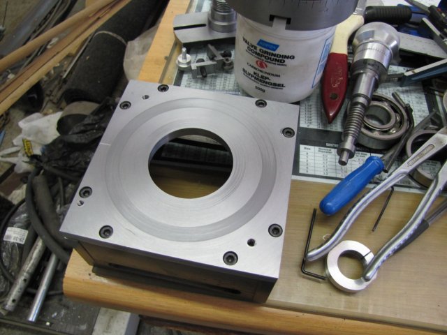
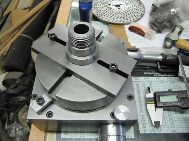
Then I proceeded to face this side of the mounting as well; not really needed, but does look neater, and then turned a spindle nose replica of my lathe on the front section, leaving a bit of clearance so that a mounted chuck will not come into contact with cap screws used for mounting the adapter to the table. I didn't take photos of the process, as I thought I'd just link to a similar adapter I made when I built my collet chuck Turns out, back then I forgot to take some photos :-[ Next time, I won't forget.

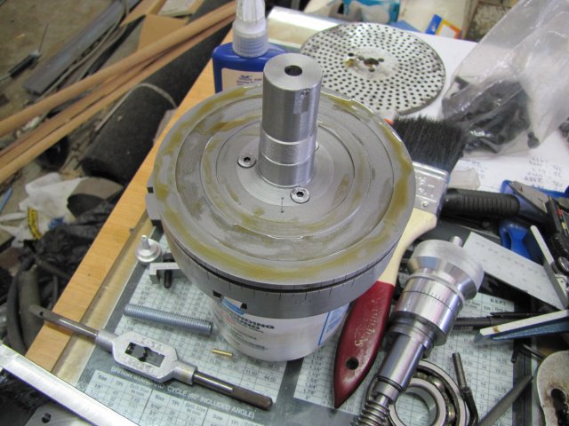
This was the end result of the operations:
normal_IMG_1406.JPG


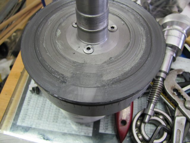
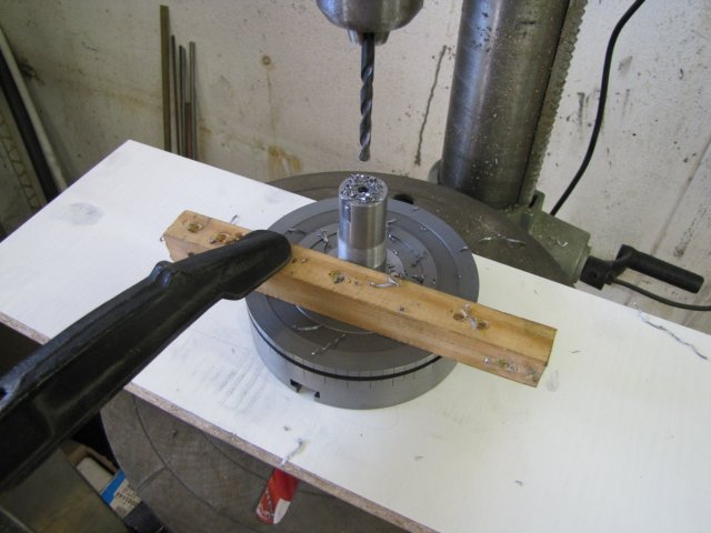
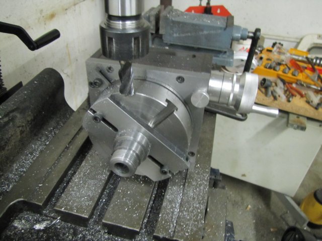
Just for fun, I put the RT to use to clean up the ugly ends of the adapter:
normal_IMG_1407.JPG

I'm very glad I did this trial run; it uncovered some hiccups - easily addressed once I do a strip and re-assembly of the RT. For one, the pre-load on the bearing is not enough as it is assembled now. I had the grub screws holding the worm and the wheel come loose from vibration, so at next assembly, I'll use some thread locker on them.

This is what the lot looks like with my 3-jaw chuck mounted on it:
normal_IMG_1408.JPG


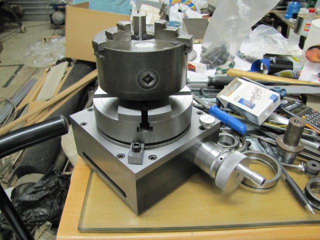
I was wondering how I am going to keep my chucks from unscrewing from the adapter while in use, and I already had a whacky idea drawn up - but I'm not going to use it... Seeing everything assembled like this, a far simpler idea struck me; it will be easy to make "clamps" that can be mounted in the unoccupied T-slots on the table that will both lock the chuck as well as add some additional rigidity ::)

Regards, Arnold
 
That's a good, sturdy looking outfit, all said and done. Looks great too.
That 'new tool' smell should last a long time, since you installed it yourself!

You're quite a builder, Arnold. I'll bet we'll be seeing this one a lot in your future threads.

Dean
 
That's a great looking setup. Where's the stepper motor and keypad? :big:
Rich
 
Lovely neat job Arnold

Stew

Just had a thought your face plate will fit on their, how about your ER collet adaptor ?.

Stew

 
Hi Arnold,

Love the work you have done with the RT. I have attempted making a few tools around the workshop, but nothing like this! It must be immensely satisfying to use it! Much more fun than using a bought RT. Congratulations on a fine project. My favorite parts was the gear cutting. Thanks for posting,

Ben
 
that is just so nice its not funny
 
Dean, Thank you ;D - I'm not going to bet against you ;)

Thanks Rich ;D - No CNC in my shop ;) - I do machining to get away from computers! Well, there is a power feed for the mill in the pipeline, and maybe a small home-brew cnc "engraving" machine to make name plates and such - very distant though...

Stew, thanks mate ;D

Thank you Ben ;D Like I mentioned; there's a couple of nigglys to sort out with it still, but the bit I've used it, it is very nice. I also enjoyed the gear cutting immensely - one of my future projects will require making an internal gear; that should be fun as well ;D

Thanks metalmad ;D - maybe not funny, but it sure was a lot of fun ;)

The final bits will now have to wait for coming weekend; my entire week's evenings are pre-booked. Hopefully I can finish everything completely on Saturday, so that I can start on an engine for a change!

Regards, Arnold
 
Well, the RT is finally done... (for now :big:)

I first lapped it with some valve grinding compound after some disassembly - here I just applied the compound to the raised edges on the table:
normal_IMG_1412.JPG


The next two photos show the progress of lapping after about 10 minutes of vigorously turning the table through turns clockwise and anti-clockwise. I just rubbed away the grinding pate with a finger to check.. :
normal_IMG_1413.JPG

normal_IMG_1414.JPG


Notice how the inner face ring on the table is less affected than the outer face ring... ; I expected this, as my lathe faces slightly concave (by design), and with the facing operations on both the base plate and the table base, this effect was doubled.

After another bit of lapping (20 more minutes), and a very thorough clean-up (ending in the kitchen sink with dish-washing liquid), this is what the base top looked like:
normal_IMG_1416.JPG

Maybe I should have done a bit more lapping, but this "felt" OK.

One last machining job, that should have been completed earlier (I forgot :-[) was to make an M6 threaded hole in the "bottom" of the main shaft. I chose M6, as the tapping drill for it is 5mm; this is one of those convenient sizes where you can shove an M5 bolt through the hole to clamp something down from the top of the RT table, as well as use an M6 bolt to "press out" a working piece from the bottom of the RT if something came stuck in the RT shaft. Here I'm drilling the 5mm hole on the drill press:
normal_IMG_1415.JPG

The shaft already had a center-hole drilled in it from the previous machining - so just picked that up in the drill press.

Next I thoroughly cleaned the bearing and use some good quality "LE" grease that my Dad (Swarfmaker) donated to me to lubricate the bearing - thus far, it has been running on oil.... :
normal_IMG_1417.JPG


Then I applied copious amounts of way-oil (the same I use for my lathe ways; a sticky thick oil) to the table, and started assembling the RT once again:
normal_IMG_1418.JPG


During assembly, I used medium strength thread retainer on all screws and the worm and driver shaft. This should prevent the screws from loosening like I found from first use, but be "easily" enough removable to disassemble the RT for maintenance. I can kick my own butt for not adding a pressure forced oil-hole in the table top to "inject" oil for lubrication; hence the finally done "for now" start of the post. I think I might be adding an oiler in future..., But for now, it's done ;D

This has been an immensely satisfying project, and MANY thanks goes out to everyone who contributed, supported, encouraged and provided valuable input along the way. There's no final photo, as it would look just like the photo of the RT assembled earlier on.

I've had indecisive feelings about my next project out of three... My sister was visiting me this week from 1400km away and I C-o-C'd her the choices. From the three choices she had, she chose Elmer's "Comber", so tomorrow I'll be starting on that ;D

Regards, Arnold
 
Arnold, Chesterfields!??? (see post #140 item 6) Good Lord, those things will kill you man! :big:

I am constantly amazed at your well thought out and executed procedures. They seem so effortless, and to see such quality work is a pleasure to witness. Marvelous job my friend, it is always a interesting item to hear you speak of and explain your problems and workarounds as they present themselves. BRAVO! :bow:

I am anxiously awaiting to see your next endeavor with baited (albeit smelly ??? ???) breath.

:hDe: Does anyone have a Tic Tac? Rof} Rof}


BC1
Jim
 
Just finnished reading the whole story.....

A truly magnificent piece you ended up with there Arnold, one that any machinist would be proud of.

Well done, and thanks for the wonderful tutorial as well.

Cheers, Neil

 
Thanks Jim ;D - those Cesterfields are a vice of mine :hDe: Got to kick that habit somehow, though I smoke a lot less while machining. Guess I'll just have to make more chips :big: No Tic Tacs needed; keeps open one's personal space in crowded areas; I use garlic for that :big:

Thank you Neil :) - it wasn't intended so much as a tutorial as just a log of how I attempted it and to try to contribute back to the community; I learned a heck of a lot from members here and on other sites, even while building the RT, so it's only fair that I at least try and put something back. Nothing in what I described is fixed; a lot of the operations could be done in alternate ways. The favourite personal lesson I learned from this build: Even a relative newbie like myself can build some decent tooling if you really put your mind to it and is prepared to make an effort.

Kind regards, Arnold
 
Arnold,
Even a relative newbie like myself can build some decent tooling if you really put your mind to it and is prepared to make an effort.

Very good and true words. That is what home machining is all about.

You only get out what you are willing to put in.

You have really shown with this post, that even with limited resources and basic techniques, wonderful things can be made.


John
 
Arnald just found this thread and just wanted to say nice job. I wanted to try one myself but I,m scared to try it maybe I will after seeing what you have done. But you are far and away better than me but nothing ventured
nothing gained.:hDe:
 
Simply Brilliant work Arnold, my hats off to you.

Shawn
 
Hi Arnold,
You letter stamp holder is just brilliant.Been racking my brains to figure out how to stamp the dial with numbers aligned.
The early lathe dials from India were awful looking with numbers stamped haywire.They make good lathes.
Plan to rebuilt a 3" R.T. sometime next year.
Will earmark this thread for future ref.

Hi Arnold,
Subsequent to above and to show support of your project,I am building one RT too.Was on a visit to my air receiver fabshop supplier,I had him fabricate the box frame and oxy-cut the square flange.Even had a spare set to back up just in case I goofed.See foto.
Did Trade School for three years way back in 1961. However did not pursue
the trade further as a machinist and hence my skill is very basic. Your thread
has given me so much know how. Will try best to measure up here in faraway Singapore.

IMG_0028.jpg
 
Hi Arnold,
Plan to use same bearings.Please advise maker and his part number. Trust the weather is fine over at your end.
 
Hi Guys,

Bugger ! I've just discovered this great post on building an RT...
I ordered a new one yesterday.
This would have been a great build project for me.
mad.gif


wallbash.gif
wallbash.gif
 
Arnold, I have to say you RT is very impressive, well documented and I would like to thank you very much for posting this here and by doing so allowing the rest of us to be able to learn from what you have done, and honestly it gives us all a quality of workmanship to aspire to :)

I will be using yours and other peoples build logs on the rotary tables when I make my own some time, and I would like to thank all you guys who have made them and posted build logs, it really helps us amatuers learn and gives us guidance and a much better understanding of how to go about it :)

Who would have thought that we could use a spiral tap to cut a worm wheel (for example) or that really machining a worm is no different to cutting a thread... Honestly making a hob - I could not get my head around until I saw your thread Arnold, and for Mike (I think was the one who used the spiral tap) bleedin' brilliance :) and Dean, I have even looked up the link arnold posted here to your build and I am so glad Arnold shared that link too :)

You guys really do rock!!!
 

Latest posts

Back
Top