Brian does Popcorn

Home Model Engine Machinist Forum

Help Support Home Model Engine Machinist Forum:

This site may earn a commission from merchant affiliate links, including eBay, Amazon, and others.
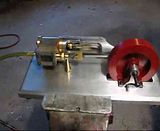
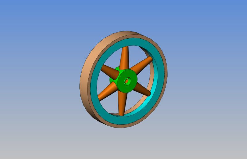
Gentlemen--We have a runner!!! I spent the day fitting my pile of Popcorn parts together, and a long, tedious day it was. Both my 10-24 die and my 5-40 die were so dull that I had to buy new ones and rethread everything. Then I managed to break the 1/8" dia. control rod off flush with the surface of the eccentric strap. However, luck was with me and I was able to drill it out, rethread, and save the part. When I set the cam I followed Elmer Verburgs instuctions---Set the piston at either top or bottom dead center, and set the valve exactly in the center of its travel. After assembly, the engine was very stiff, but after an hour of "running in" with my electric drill motor, it freed up considerably. I wanted badly to try the engine out, but haven't yet built a flywheel for it, so I robbed a flywheel off of the Chucks Hit and Miss Air Engine that I built two or three years ago, as it was close to the right diameter and width. I had to open the bore up from 1/4" to 5/16" and machine about .040" off the width. I plugged the air in and opened the valve, and to my great pleasure the engine started immediately and has been running in my basement for the last two hours. I will be building a "fancy" flywheel for it, but that will be sometime in the next two weeks. I'm posting this from my wifes laptop computer, because my big computer is temporarily across town at an industrial plant where I am working a temporary engineering/design contract.
 
Thm: Thm:
Gail in NM
 
Very nice work Brian, and very nice of you to share it with all of us.

I have one nit to pick. You refer to adjusting the cam. In steam engine terms its called an eccentric. I know it acts like a mechanical cam, but in all steam terminology its called an eccentric.

Whatever you want to call it, its still very nice work.
 
Thanks for another great design. Anxious to build this one.

Larry
 
If anyone wants to go ahead with this build, all of the posted drawings are correct. I will be adding a pdf download file later this week, because I don't know how well the .jpeg files I have posted will print out. One warning though---This engine is not for "newbee" machinists. Thre is a lot of complex and finicky work in that crosshead guide, and it is really the main showpeice of this engine. ---Brian
 

Wonderful engine Brian. Thanks to both You and Stew for the development and great drawings.
I've fancied the Cretors version for a long time and now have good incentive to build one.

Regards,
Mike
 
Really nice engine. Thanks for sharing the build and the plans!!
 
Not having my big computer at home is making me a bit crazy!!! I have come up with a really nice way to make a built up flywheel, and although I have modelled it in 3D, I have no way currently to post it. I have been going in to work a bit early each morning and pulled detail drawings off the model so that I can proceed with the build in the evenings, and so far I have completed the two part outer rim (in bronze) and the hub (in brass). Although I have brass here to make the spokes from, I might get radical and make the spokes from aluminum for the contrast. Since no soldering is required, this is an easy thing to do. My spokes will not be bent like the ones pictured in the drawing of the engine, but will be tapered----large at the hub and small at the outer rim. Not great from an engineering standpoint, but it looks slick!!! I think that when I get my computer back next week, I may start a seperate thread on the building of the flywheel. It feels realy weird after 10 years to be going across town to someone elses factory to do my thing, but its an interesting project. The company I am doing the design work for makes metal spinning lathes for industry, and I am helping design the automatic feed and part removal system for a large new metal spinning lathe.
 

Pat Joorgensen (BigonSteam) and I have been corresponding on a couple of engines, including a Cretors. I use Alibre, and Pat uses both SW and Alibre. The problem with Alibre is that while it can export STL, it cannot import it (at least my version can't). I can export the STL but I can't examine the output to see if it is smooth enough.

There are some parameters in Alibre which determine the quality of the STL it outputs, but since I can't see the effect they have, I just aimed fairly high. The result is over 45mb and so I put it here: http://www.mediafire.com/?6b9pqobciw4jjk5

Please post to let us know if it will work out for cnc.

 
I was able to load the STL file into CamBam, but as I have not previously tried any 3D milling I am not sure how to generate the g-code. I posted a thread over at the CB forum asking for advice. Since CB wants to mill surfaces, I suspect that the file it needs would have just the spokes and the inner rim as a separate surface from the rim, and also not to have the hole in the center. The actual rim would be turned on the lathe or milled 2.5D.

I'll report back when I have some idea how this needs to go, but in a different thread so as not to hijack Brian's build further.
 
This is the flywheel I am building for the Popcorn engine. I have started a seperate thread for it, titled "Built up Flywheel-2011".
BUILTUPFLYWHEELASSEMBLY.jpg
 
As promised, here are all the files required to build the "inch" version of the Popcorn engine. You will have to buy two metric 2-flute end mills, a 2mm and a 3mm to machine the steam ports in the cylinder. I have not included the plans for the flywheel because it is still a "work in progress". The flywheel is 3.5" o.d. x 1/2" wide with a 5/16" center hole. Stew Hart did the original metric design of this engine, and I took Stew's drawings and bastardized them into British Imperial, with a few changes but not many. If you download and/or use these files please give me a Karma point-----and give Stew Hart one as well, because without Stew firing my imagination and posting the original metric plans, this wouldn't have happened.---Brian

http://www.mediafire.com/?akf34e4hcok5i04
 
I'd like to see a short straight section on the spoke where it exits the hub. I think the taper to the end would make it hard to fit the spoke in the hub without showing a gap. Some flutes in the spokes would maybe add a nice touch too.
 
Brian-

These files are for the OVERCRANK engine which I already have.

Larry
 
Brian I have given you a karma point for your overcrank which I am halfway to finishing (don't get too excited a lot of my stuff gets to that point :big:) so am looking forwards to this project as well. :bow: Stew is in line for a point too ;D
Pete
 
If anyone is crazy enough to want to build this multi part flywheel, I have posted .pdf files with the posted drawings over on the "built-up Flywheel--2011" thread.
 
Back
Top