Brian does Popcorn

Home Model Engine Machinist Forum

Help Support Home Model Engine Machinist Forum:

This site may earn a commission from merchant affiliate links, including eBay, Amazon, and others.
Jerry---Thats a great animation!!! ----3D modelling is like a giant magnet---It sucks you in and keeps you learning more as you use it because it is so fascinating. I've only been using 3D for 10 years, and of course it wasn't available when I started in engineering 46 years ago. My God, if it had been available back then, I can't even imagine what it would be capable of now.
 
Jerry

Very impresive work, I'll have to get my head round this 3D stuff.

Stew
 
Brian

Thanks for the kind words. All the more appreciated in light of your modeling mastery.

Stew - After some initial frustration, the light will go on and you will enjoy the benefits. It is almost as much fun as machining metal and the cleanup is a lot easier. Its also a way to work when the shop is too hot or too cold.

Jerry
 
My stockpile of British Imperial Popcorn parts is growing, and this morning I got to do something I had never done before. I machined the outer profile of the cylinder, which is only half round. This operation has always puzzled me, because you have a round part that obviously can not be turned on a lathe!!! Yesterday I studied Stew Harts post on making his cylinder, (Thank you Stew) and I assume that he must have one of those combination lathe and mills. after seeing his method, the light came on, and I proceeded to use the same method on my machinery. I machined the overall rectangular cross section shape from brass, but made it about 1/2" longer than the cylinder length, then drilled and reamed a 0.5" hole all the way through it in the correct place using my mill/drill. I then slid it over a 1/2" peice of cold rolled steel shaft, and cross drilled in that extra 1/2" of material for a 3/16" spring pin. Then it was taken to the lathe where one end of the cylinder was "faced" to ensure it was square to the bore.
CYLINDERMACHINING001.jpg

CYLINDERMACHINING002.jpg
 
I then set my rotary table with the 3 jaw chuck attached up on the mill table, and chucked up the 1/2" cold rolled rod. I centered the spindle over the center of the 1/2" rod, and using a 3/8" end mill I took about a zillion passes back and forth parallel to the centerline of the peice at full depth with spindle height locked. Each time I took a pass with the milling cutter from end to end, I would advance the rotary table about 5 or10 degrees, and repeat the passes with the milling cutter. The reason that I set the cutter at full depth and locked it is that when you first begin to cut, the tip of the cutter is just "kissing" the material, and its the turning of the rotary table that actualy presents more and more material to the cutter as the part revolves. This method worked amazingly well, and now I've done another 'New Thing' with my equipment.
CYLINDERMACHINING003.jpg

CYLINDERMACHINING005.jpg
 
Nicely done Brian:- thats more or less what I did except I din't use a cross bar, I turned a 1/2" dia mandrell up and bolted the cylinder to that, and used a small fly cutter.

131_0496-2.jpg


131_0499-1.jpg


Ther's more than one way to skin a rabbit.

Stew
 
I've done something that might be considered "dumb" in some circles!!!! As I converted this engine from Metric to British Imperial, I carefully changed the bores to accomodate my 1/2" and 5/8" reamers. I changed all the fastener holes to suit my favourite #5-40 taps. I changed the non critical bores to correspond to my 3/4" drill instead of the 20mm Stew had used. I changed the radii on the cut-outs in the crosshead guide to suit my 5/8" ball nosed endmill. However, I went blithely along with Stews metric offset for the cam and actually built the cam. It was only today as I whittled away on the cylinder that I realized I hadn't changed the slotted steam passages to correspond to an Imperial sized endmill. I didn't want to remake the cam, and the cam offset has to interact correctly with the size and spacing of the steam passages in the cylinder. I agonized over just how to get around this issue, then said "To heck with it!!!" and went over to my toolshop and bought a 2mm and a 3mm endmill. So----When I get around to posting all the drawings with "Imperialized" dimensions----Anyone considering building the engine from these plans will have to pony up $10 for a couple of metric end mills. And I have to tell you---Its a damn ticklish job, making a slot the depth required with a 2mm endmill!!! I think I held my breath the entire time I was cutting the slots, but all went well.---Brian
 
:big: :big:
I know what you mean hold your breath small end mills just need to many RPM's to do real well.

I don't think my flywheel for the Atkinson I'm working would work to well it is probably bigger then your whole motor will be. :big: :big:

Things are looking good Brian!
 
Brian

If you change the steam ports the slide valve has to change to match, i can't do it just now but some time next week, I,ll post the imperial sizes.


Stew
 
For those who don't have a dividing head or a horizontal rotab, there's a couple of other ways to get a half-round cylinder profile.

With a vertical rotab you can cut the profile with the side flutes of an endmill. This gives a radius at the ends of the profile, but a small endmill to finish and/or filing can square it up.

In Kozo's A3 book he shows mounting the cylinder on a lathe and using the carriage with a parting tool mounted sideways to act as a shaper.
 
Well, the fat lady hasn't sang yet, but we're a lot closer to a British Imperial (inch) Popcorn engine!!! I must say, those pretty little bearing stands are a pain in the butt to whittle out, and I have never built an engine with "glands" on the cylinder and steamchest before, but so far, things are going very well.
popcornpartialassembly002.jpg

popcornpartialassembly001.jpg
 
Wow Brian - That is sure looking good! Thm:
Can't wait to see it run...

Harold
 
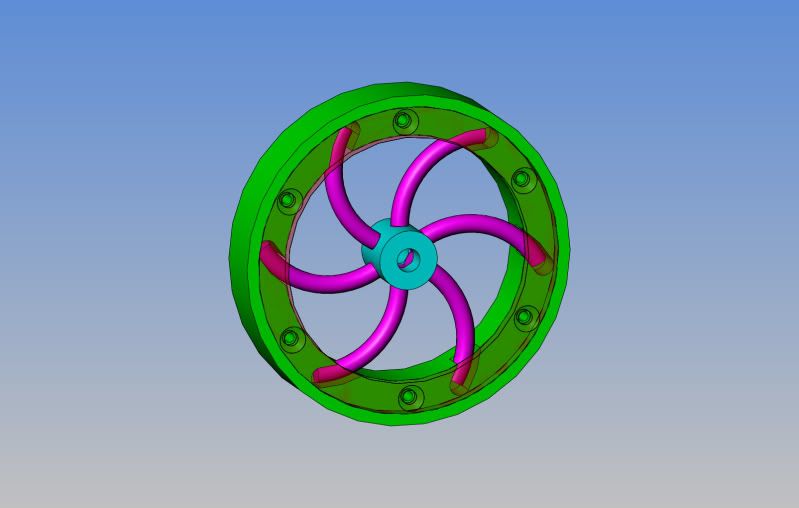
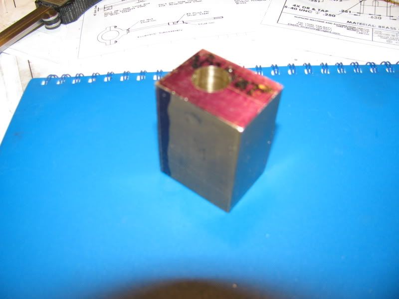
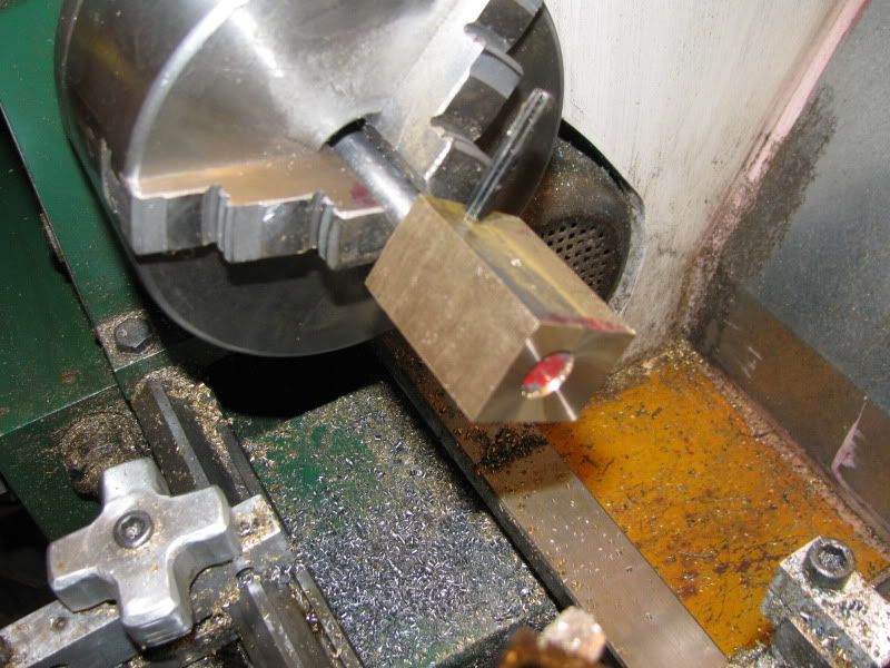
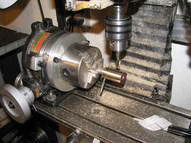
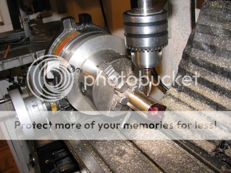
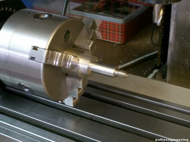
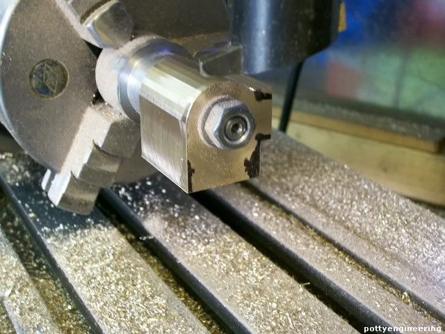
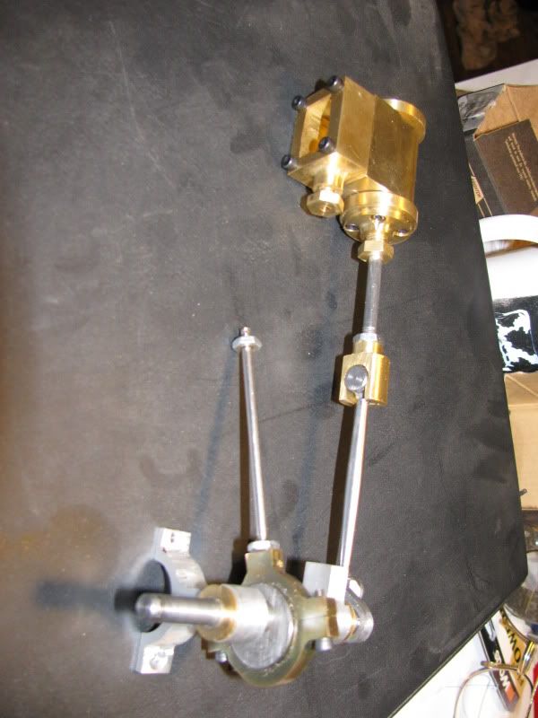
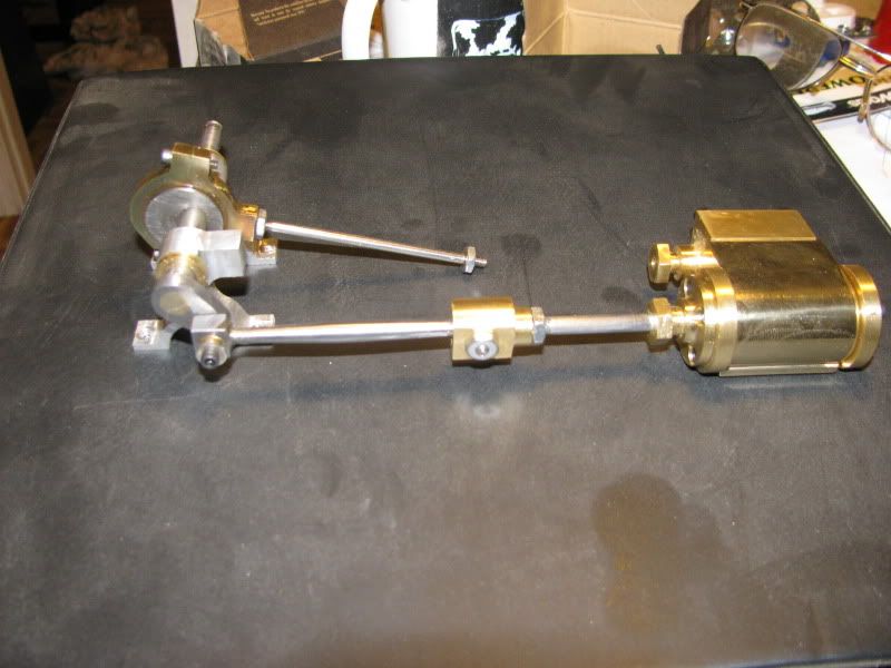
The credit here mostly belongs to Stew Hart. Stew was going like gangbusters on his Metric build of this engine, then got slowed down by some family commitments. I have been slogging away on this build, converting mostly everything to decimal inches, and trying not to outpost Stew. I have yet to make the crosshead guide, which is a fairly complicated peice, and a base. I am rather torn as to what to do about the flywheel. I would like to do something fancy, perhaps a bit larger in diameter than what stew had originally posted in his plans, but I've actually been too busy to give it much thought as yet. I have a peice of 3/16" Lexan that I want to use for the steamchest cover. Every time I build one of these small cylinders, I am absolutely dazzled by how many set-ups and machining operations are involve with them------------And this time, none of my threaded fasteners break thru into the cylinder bore!!!
 
I am thinking of making a built up flywheel with 3/16" or 1/4" steel bent spokes. I would bend them somewhat similar to the spokes in Stews drawing, silver solder them into holes in an inner hub, and set the outer ends into cavities machined in the side of a bronze outer rim, with a 0.100 steel side cover plate screwed onto the side of the bronze to lock them in place.---still in the thinking stage.
 
Brian - I did a little YouTube surfing for Cretors popcorn Engines and saw a number of examples of both models and restored originals. One of the things I noticed on them is the mounting of the flywheel between the bearing stands as on this one:

[ame]http://www.youtube.com/watch?v=44iFMcn-jB0[/ame]

None of them show how power was transmitted to the rest of the machinery but I would guess that there would be a belt drive pulley outboard of the bearing on the flywheel end of the shaft, probably for round belting.

When you get around to making the Xhead guide, be careful of the relationship between the end bore depth and the side cuts. I downloaded your 3D parts and spent some time looking at that part. In your model, the bore is VERY near to breaking through onto that nice visible curved face. I guess you will do the bore first and then mill the face with a ball end mill. Just be careful, I know how much it hurts to mess up when you're that far into the part and that curved face is one of the main eye attractors on that part.

You assembled parts are looking great. And as usual, fast. Nice work.

Jerry
 
Kricky Brian you've realy steamed along with this, I recon between us we've now got enough parts to complete an engine.

Have you got any ideas for bells and whistles for the enigine, i've got a governor and stop valve sketched up, and ideas for a whistle and displacement lubricator more or less sorted, plus a little suprize to finish with ::)

:big: :big: :big:

Stew

 
All I have at the moment is a variation on your curved spoke flywheel. I don't really plan on the bells and whistles approach, I'll leave that up to you Stew. I'm just aiming for a running engine. Jerry does have a good point about the flywheel being between the bearing supports. This leaves lots of access at the outer end of the crankshaft for a drive pulley to power some device. I like that idea. I haven't made a base yet, so I may move the flywheel inside. There will definitly be a cut-out in the base to clear the flywheel diameter----Possibly four stubby legs on the under side of the base as well because a 3 1/2" dia. flywheel will hang below the base. Jerry---I had caught what you are talking about on the crosshead guide, so have altered it a bit to keep it from breaking through. As I said in an earlier post, it is not uncommon for me to create all of the models, then end up going back and "tweaking" them as I do the detail drawings and notice thngs being a bit "tight" in areas.---Brian
popcornflywheelbentspokes.jpg
 
Brian Rupnow said:
I am thinking of making a built up flywheel with 3/16" or 1/4" steel bent spokes. I would bend them somewhat similar to the spokes in Stews drawing, silver solder them into holes in an inner hub, and set the outer ends into cavities machined in the side of a bronze outer rim, with a 0.100 steel side cover plate screwed onto the side of the bronze to lock them in place.---still in the thinking stage.

Brian, here's a brief pictorial on curved spoke flywheels built up by Find Hansen. The result is a right nice looking flywheel.

Curved%20spoke%20flywheel.html


Chuck
 

Latest posts

Back
Top