BobWarfield
Well-Known Member
- Joined
- Dec 27, 2007
- Messages
- 1,151
- Reaction score
- 1
Sandy, you raise some interesting points. I see now that my drawing has the timing 90 degrees out of phase with the max speed timing. My version would run very slowly. Max performance would inject max steam with the piston at top.
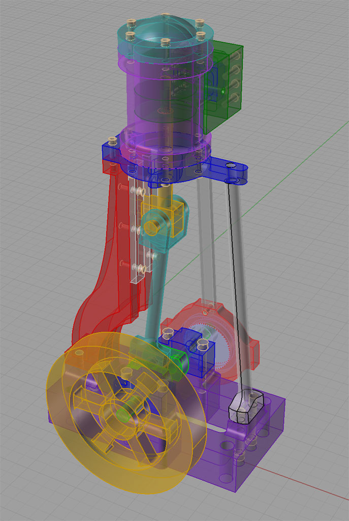
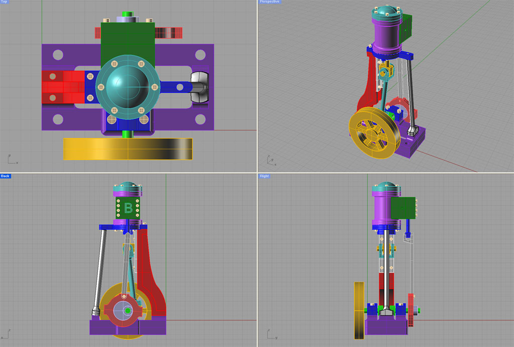
The point you make about the efficiency of large versus small steam ports is an interesting one too. You're looking to maximize the expansion ratio available for efficiency's sake. This is another neat thing you can do with the CAD program: you give it a shape, it tells you the volume. So I took a look at the volume of the steam ports--my design is 2.4 times the volume of the other. But what impact does this have? It changes the volume at top of stroke by only about 5%. Methinks that can't have a big effect on performance. With CNC, it would be so easy to simply make up both steam port variations that I am inclined to do so and observe under actual test conditions which one appears to work better. If I don't like the large additional port area, it's trivial to just cut an arc of lesser extent with the endmill right back to plunging the cutter with no arc. The point was really to save the angled set up and provide clearance around the piston.
After a little search, I found there is more at work here than has been discussed. Clearly there is some size port that is simply too small to flow enough steam relative to the timing of the engine to be efficient. The question is what that size may be? There may be a size that is too large as well because of the deleterious compression effect you mention. I did find a fascinating a fascinating discussion of this here:
http://www.trainweb.org/tusp/philosophy.html
The Wardale entry does suggest maximizing the flow characteristics of the steam input in a way that will increase their volume it seems. These suggestions are pretty similar to internal combustion hot rodding in many ways. The emphasis in any case is on maximizing the pressure differential between intake and exhaust.
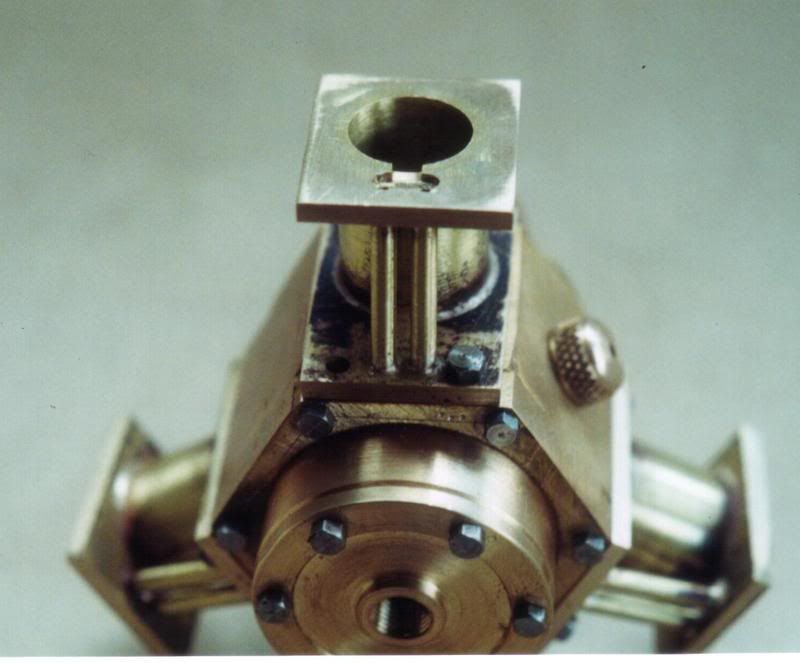
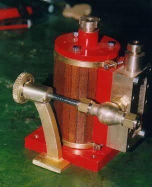
Lastly, this valve timing thing is troubling. Not so much from the standpoint of the eccentric gear. If nothing else, a Stevenson linkage lets me vary that timing continuously after the fact so I can find the sweet spot empirically if nothing else! Rather, I'm troubled in considering the effect on timing that the relative dimensions of the slide valve, the stroke of the slide valve, and the steam ports will have on the engine's effective timing. The example I used was Bentley's, and it's pretty straightforward. From the photos, he's got three passages identical to mine and a slide valve cavity that just covers 2 adjacent passages. There is not a lot of "dead" area on the valve in his design to block off all the passages without exhausting in order to let steam expansion do it's work. The literature certainly talks about injecting high pressure steam and then letting it expand. It appears to me that most of the model slide valves I've seen don't do this very effectively. Instead, steam seems to be feed pretty continuously through the power stroke and then we abruptly switch to exhausting.
Have I misunderstood these designs or is that in fact what is happening? I suspect I need to go back and look carefully at the impact of those relative dimensions. I suspect small changes might have a big impact.
I recognize that in all likelihood the little models are greatly simplified relative to their prototypes and probably are not anything remotely close to design efficiency. That's fine, I'm not building a moon shot here, I'm just curious.
Cheers,
BW
The point you make about the efficiency of large versus small steam ports is an interesting one too. You're looking to maximize the expansion ratio available for efficiency's sake. This is another neat thing you can do with the CAD program: you give it a shape, it tells you the volume. So I took a look at the volume of the steam ports--my design is 2.4 times the volume of the other. But what impact does this have? It changes the volume at top of stroke by only about 5%. Methinks that can't have a big effect on performance. With CNC, it would be so easy to simply make up both steam port variations that I am inclined to do so and observe under actual test conditions which one appears to work better. If I don't like the large additional port area, it's trivial to just cut an arc of lesser extent with the endmill right back to plunging the cutter with no arc. The point was really to save the angled set up and provide clearance around the piston.
After a little search, I found there is more at work here than has been discussed. Clearly there is some size port that is simply too small to flow enough steam relative to the timing of the engine to be efficient. The question is what that size may be? There may be a size that is too large as well because of the deleterious compression effect you mention. I did find a fascinating a fascinating discussion of this here:
http://www.trainweb.org/tusp/philosophy.html
The Wardale entry does suggest maximizing the flow characteristics of the steam input in a way that will increase their volume it seems. These suggestions are pretty similar to internal combustion hot rodding in many ways. The emphasis in any case is on maximizing the pressure differential between intake and exhaust.
Lastly, this valve timing thing is troubling. Not so much from the standpoint of the eccentric gear. If nothing else, a Stevenson linkage lets me vary that timing continuously after the fact so I can find the sweet spot empirically if nothing else! Rather, I'm troubled in considering the effect on timing that the relative dimensions of the slide valve, the stroke of the slide valve, and the steam ports will have on the engine's effective timing. The example I used was Bentley's, and it's pretty straightforward. From the photos, he's got three passages identical to mine and a slide valve cavity that just covers 2 adjacent passages. There is not a lot of "dead" area on the valve in his design to block off all the passages without exhausting in order to let steam expansion do it's work. The literature certainly talks about injecting high pressure steam and then letting it expand. It appears to me that most of the model slide valves I've seen don't do this very effectively. Instead, steam seems to be feed pretty continuously through the power stroke and then we abruptly switch to exhausting.
Have I misunderstood these designs or is that in fact what is happening? I suspect I need to go back and look carefully at the impact of those relative dimensions. I suspect small changes might have a big impact.
I recognize that in all likelihood the little models are greatly simplified relative to their prototypes and probably are not anything remotely close to design efficiency. That's fine, I'm not building a moon shot here, I'm just curious.
Cheers,
BW
")